

Analysis of 320X240 uncooled microbolometer focal plane array ...
Analysis of 320X240 uncooled microbolometer focal plane array ...
Analysis of 320X240 uncooled microbolometer focal plane array ...

You also want an ePaper? Increase the reach of your titles
YUMPU automatically turns print PDFs into web optimized ePapers that Google loves.
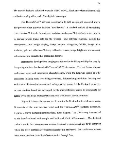
34The module includes colorized output in NTSC or PAL, black and white radiometricallycalibrated analog video, and 12 bit digital video output.The ThermaCAMim s<strong>of</strong>tware is applicable to both cooled and <strong>uncooled</strong> <strong>array</strong>s.The process <strong>of</strong> the s<strong>of</strong>tware includes "equalization," a standard method <strong>of</strong> determiningcorrection coefficients in the computer and downloading coefficients back to the camera,to acquire proper frame data for the process. The s<strong>of</strong>tware functions include filemanagement, live image display, image capture, histograms, NETD, image pixelstatistics, gain and <strong>of</strong>fset coefficients, calibration curves, image brightness and contrast,colorization, and several other specialized features.Inframetrics developed the imaging test fixture for the Honeywell bipolar <strong>array</strong> byintegrating the interface board with ThermaCAM Thi electronics. The test fixture allowedpreliminary <strong>array</strong> and radiometric characterization, while the Rockwell <strong>array</strong>s and theassociated imaging board were being developed. Information gained from the <strong>array</strong> andradiometirc characterization was used to improve the system for the Rockwell <strong>array</strong> [5].,A new interface board was developed for the <strong>microbolometer</strong> <strong>array</strong>s to compensate forsignal levels and noise characteristics different from that <strong>of</strong> photon detectors.Figure 3.2 shows the camera test fixture for the Rockwell <strong>microbolometer</strong> <strong>array</strong>.It consists <strong>of</strong> the new interface board and the ThermaCAM TM platform electronics.Figure 3.3 shows the test fixture functional block diagram. The UFPA <strong>array</strong> is connectedto the interface board with sample and hold, and 16-bit AID converter. The digitizedvideo is sent to the video processor module for signal processing and also to the computerwhere the <strong>of</strong>fset correction coefficient calculation is performed. The coefficients are sentback to the interface board for <strong>of</strong>fset correction through DIA.


