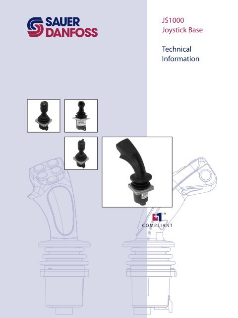
JS1000 Joystick Base Technical Information ©Sauer-Danfoss
JS1000 Joystick Base Technical Information ©Sauer-Danfoss
JS1000 Joystick Base Technical Information ©Sauer-Danfoss

You also want an ePaper? Increase the reach of your titles
YUMPU automatically turns print PDFs into web optimized ePapers that Google loves.
<strong>JS1000</strong><br />
<strong>Joystick</strong> <strong>Base</strong><br />
<strong>Technical</strong><br />
<strong>Information</strong>
Revision History<br />
<strong>JS1000</strong> <strong>Joystick</strong> <strong>Base</strong><br />
<strong>Technical</strong> <strong>Information</strong><br />
Revisions<br />
© 2010 Sauer-<strong>Danfoss</strong>. All rights reserved.<br />
2 520L0826 • Rev GA • Nov 2010<br />
Table of Revisions<br />
Date Page Changed Rev<br />
18 Nov, 2010 8, 23 PRO grip is only available in a top mount configuration.<br />
Supply voltage is 9 to 32 Vdc.<br />
GA<br />
29 Mar, 2010 5, 8, 11, 23, Grip options, SAE J1939 CAN Message Specification,<br />
FA<br />
various Electrical and Environmental Characteristics, formatting<br />
05 Mar, 2010 5—7,<br />
17—20, 22<br />
Features, model code, dimension drawings EA<br />
14 Sep, 2007 Various Standard CAN option information added; revised CAN<br />
Message Protocol section; and varous specificatios revised<br />
DA<br />
12 Dec, 2005 9, 23 Pro grip side switch color table and Repair section C<br />
28 Nov, 2005 Various Feature updates B<br />
27 Jul, 2005 Various Content revised A<br />
17 Dec, 2004 First edition<br />
Sauer-<strong>Danfoss</strong> accepts no responsibility for possible errors in catalogs, brochures and other printed material.<br />
Sauer -<strong>Danfoss</strong> reserves the right to alter its products without prior notice. This also applies to products already<br />
ordered provided that such alterations can be made without affecting agreed specifications. All trademarks<br />
in this material are properties of their respective owners. Sauer-<strong>Danfoss</strong>, the Sauer-<strong>Danfoss</strong> logotype, the<br />
Sauer-<strong>Danfoss</strong> S-icon, PLUS+1, What really matters is inside® and Know-How in Motion are trademarks of the<br />
Sauer-<strong>Danfoss</strong> Group.
<strong>JS1000</strong> <strong>Joystick</strong> <strong>Base</strong><br />
<strong>Technical</strong> <strong>Information</strong><br />
Contents<br />
General <strong>Information</strong> Product Overview .......................................................................................................................................... 4<br />
Features and Options .................................................................................................................................... 5<br />
Theory of Operation ...................................................................................................................................... 5<br />
Product Configuration Product Configuration Model Code ........................................................................................................ 6<br />
<strong>Base</strong> Model Code ............................................................................................................................................ 7<br />
<strong>Base</strong> Part - A, B, C, and D ......................................................................................................................... 7<br />
Grip Model Code ........................................................................................................................................... 8<br />
<strong>Base</strong> Part - E ................................................................................................................................................. 8<br />
<strong>Base</strong> Part - F ................................................................................................................................................. 9<br />
<strong>Base</strong> Part - G, H, and J ............................................................................................................................10<br />
<strong>JS1000</strong> CAN Messages<br />
and CAN Message<br />
Protocol<br />
SAE J1939 CAN Option ...............................................................................................................................11<br />
SAE J1939 CAN Message Specification .................................................................................................11<br />
SAE J1939 Basic <strong>Joystick</strong> Message ....................................................................................................11<br />
Data Field ...................................................................................................................................................11<br />
Basic <strong>Joystick</strong> Message Data Field Descriptions ..........................................................................12<br />
SAE J1939 Extended <strong>Joystick</strong> Message ...........................................................................................15<br />
SAE J1939 Error (DM1) Messages ......................................................................................................16<br />
PRO Grip Button and Proportional Roller CAN Naming Conventions.......................................17<br />
CANopen Object Dictionary .....................................................................................................................17<br />
Product Installation Grip with Rocker Switch Dimensions and Mounting ......................................................................18<br />
Connector Pin Assignments ................................................................................................................18<br />
Grip with Banana Switch Dimensions and Mounting .....................................................................19<br />
Connector Pin Assignments ................................................................................................................19<br />
Pro Grip Dimensions and Mounting .....................................................................................................20<br />
Connector Pin Assignments ................................................................................................................20<br />
Ball Grip Dimensions and Mounting .....................................................................................................21<br />
Connector Pin Assignments ................................................................................................................21<br />
Mating Connector Details .........................................................................................................................21<br />
Mating Connector Deutsch® DTM06-6S .........................................................................................21<br />
Recommended Wiring Practice ...............................................................................................................22<br />
<strong>Joystick</strong> Safety ...............................................................................................................................................22<br />
Specifications and<br />
Servicing<br />
CANopen Object Dictionary is on line at: www.sauer-danfoss.com<br />
(Access dictionary in PDF format under <strong>Joystick</strong>s, CANopen EDS).<br />
Mechanical Characteristics .......................................................................................................................23<br />
Electrical Characteristics ............................................................................................................................23<br />
Environmental Characteristics .................................................................................................................23<br />
<strong>Joystick</strong>s Requiring Repair ........................................................................................................................23<br />
520L0826 • Rev GA • Nov 2010<br />
3
<strong>JS1000</strong> <strong>Joystick</strong> <strong>Base</strong><br />
<strong>Technical</strong> <strong>Information</strong><br />
General <strong>Information</strong><br />
Product Overview Together with its family of associated grips, the <strong>JS1000</strong> joystick base is a high-reliability<br />
operator input device for controlling mobile machine work functions. The joystick is<br />
available in single axis spring-centered and dual axis spring-centered configurations.<br />
Both versions are available with the standard ergonomic PRO grip, ball grip, grip with<br />
integral Hall effect sensor rocker switch, and grip with integrated hall effect banana<br />
switch. The <strong>JS1000</strong> is ideally suited for low clearance and armrest mounting and it<br />
withstands the most punishing mobile machine applications.<br />
4 520L0826 • Rev GA • Nov 2010<br />
High reliability is the product design goal for the <strong>JS1000</strong>. It is resistant to the extremes of<br />
temperature, shock, vibration and EMI/RFI typically found in mobile machine operating<br />
environments. The non-contact Hall effect technology and low part count eliminates<br />
many of the failure modes associated with traditional joystick technology. The <strong>JS1000</strong><br />
design has been tested to 10 million cycles per axis with no indication of bearing or boot<br />
wear and no degradation of electrical performance.<br />
This technical manual describes the many features you can select to configure the right<br />
product for your application.<br />
<strong>JS1000</strong> <strong>Joystick</strong><br />
F101419
<strong>JS1000</strong> <strong>Joystick</strong> <strong>Base</strong><br />
<strong>Technical</strong> <strong>Information</strong><br />
General <strong>Information</strong><br />
Features and Options • Non-contacting Hall effect sensing<br />
• Available redundant sensing per axis for CAN output configurations<br />
• Single or dual axis<br />
• X-Y axis guided<br />
• Spring return-to-center<br />
• Two centering spring options<br />
• Operating life exceeding 10 million cycles per axis<br />
• Three electrical output options:<br />
– CAN 2.0B, SAE J1939 message protocol<br />
– 0.5 to 4.5 Vdc (nominal)<br />
– CAN 2.0B, CANopen protocol<br />
• IP-67 environmental rating above panel, grip dependent. IP-67 below panel with vent<br />
plug installed<br />
• EMI/RFI protected to 100 V/m<br />
• Stable null<br />
• Factory calibrated output range<br />
• Low power consumption<br />
• Multiple grip options:<br />
– Plain ball grip<br />
– Grip with rocker switch<br />
– Grip with banana switch<br />
– PRO grip<br />
Theory of Operation The <strong>JS1000</strong> base uses non-contacting Hall effect sensor technology to detect and<br />
transmit handle position. A spherical permanent magnet is attached to the base of the<br />
<strong>JS1000</strong> shaft. This magnetic ball produces a magnetic field aligned with the Z-axis. Two<br />
programmable, temperature-compensated Hall effect sensors are positioned 90º from<br />
one another along the X and Y axes of the magnetic ball. They are aimed perpendicular<br />
to each other and the Z-axis. Movement of the joystick grip and the attached magnetic<br />
ball alters the magnetic field sensed by the Hall effect sensors, causing their electrical<br />
output to change. The output changes are proportional to changes in magnetic field<br />
caused by shaft movement. This electronic design yields a linear relationship between<br />
joystick shaft position and signal output, with no hysteresis and a stable null over the<br />
entire range of shaft displacement.<br />
The programmable Hall effect sensors allow factory calibration of device null, gain,<br />
temperature coefficient and output voltage range. The joystick analog outputs are<br />
clamped to a nominal range of 0.5 Vdc to 4.5 Vdc. Any voltage outside that range can be<br />
assumed to be an invalid signal.<br />
The two grip-with-switch options that are available with the <strong>JS1000</strong> base feature a return<br />
to center Hall effect sensor rocker switch. The output range is nominally 23% to 77% of<br />
supply voltage. The output of the rocker switch can be used for state sensing (on-off) or<br />
for use as a proportional output.<br />
520L0826 • Rev GA • Nov 2010<br />
5
Product Configuration<br />
Model Code<br />
<strong>JS1000</strong> <strong>Joystick</strong> <strong>Base</strong><br />
<strong>Technical</strong> <strong>Information</strong><br />
Product Configuration<br />
6 520L0826 • Rev GA • Nov 2010<br />
Use the <strong>JS1000</strong> product configuration model code to specify particular features when<br />
ordering a <strong>JS1000</strong> joystick. The model code begins with the product family name: <strong>JS1000</strong>.<br />
Fill in the remaining fields to configure the product with the desired features.<br />
Product Configuration Model Code Example<br />
J S 1 0 0 0 X Y A J 3 3 1 T P R O R 3 R L R Y Y N R N G N<br />
Where:<br />
XY = Multi-axis movement<br />
A = Standard spring<br />
J331 = CAN output with SAE J1939 message protocol, 33 (hex) source address,<br />
1000 counts output range<br />
J33B = CAN output with SAE J1939 message protocol, 33 (hex) source address,<br />
1000 counts output range, redundant sensor<br />
TPRO = Top Mount, PRO Grip<br />
R3RL = Right hand grip, 3 buttons, 1 Roller on the Left<br />
RY = Right hand grip with Yellow side switch<br />
YNRNG = Button 1 = Yellow,<br />
Button 2 = None,<br />
Button 3 = Red,<br />
Button 4 = None,<br />
Button 5 = Grey<br />
N = No operator presence switch
<strong>Base</strong> Model Code<br />
<strong>JS1000</strong> <strong>Joystick</strong> <strong>Base</strong><br />
<strong>Technical</strong> <strong>Information</strong><br />
Product Configuration<br />
<strong>JS1000</strong> Product Configuration Model Code Example – <strong>Base</strong> Part - A, B, C, and D<br />
A B C D E F G H J<br />
J S 1 0 0 0 X Y A J 3 3 1<br />
A Product Family<br />
Code Description<br />
<strong>JS1000</strong> <strong>JS1000</strong> joystick base with Deutsch® connector, spring return-to-center<br />
B Single or Dual Axis<br />
Code Description<br />
XY Dual axis function, forward and reverse with left and right, with guided axis<br />
(force increases in the corners)<br />
NY Single axis function, forward and reverse<br />
C Center Return Spring<br />
Code Description<br />
A Standard spring<br />
B Heavy spring<br />
D1 Electrical Interface Options<br />
Code Description<br />
J CAN 2.0B, SAE J1939 message protocol<br />
P CAN 2.0B, CANopen protocol<br />
S Analog voltage output<br />
D2 CAN Source Address*<br />
Code Description<br />
NN None—use with analog outputs when D1 = S<br />
33 Source address = 0x 33<br />
34 Source address = 0x 34<br />
35 Source address = 0x 35<br />
36 Source address = 0x 36<br />
* Factory set CAN source addresses and node IDs can be changed using the PLUS+1<br />
service tool.<br />
D3 <strong>Joystick</strong> Output Type<br />
Code Description<br />
N None—use with analog output (when D1=S)<br />
1 CAN full scale output = 1000 counts<br />
B CAN full scale output = 1000 counts, redundant sensor<br />
520L0826 • Rev GA • Nov 2010<br />
1 2 3 1 2<br />
7
Grip Model Code<br />
<strong>JS1000</strong> <strong>Joystick</strong> <strong>Base</strong><br />
<strong>Technical</strong> <strong>Information</strong><br />
Product Configuration<br />
8 520L0826 • Rev GA • Nov 2010<br />
<strong>JS1000</strong> Product Configuration Model Code Example – <strong>Base</strong> Part - E<br />
A B C D E F G H J<br />
J S 1 0 0 0 X Y A J 3 3 1 T P R O R 3 R L<br />
1 2 1 2 3 4<br />
PRO grip is only available in a top mount configuration.<br />
E1 Grip Mounting Options<br />
Code Description<br />
B Bottom mount (from below the panel, no boot retainer included, boot is captured between panel<br />
and housing) with IP-67 vent plug*<br />
C Bottom mount (from below the panel, no boot retainer included, boot is captured between panel<br />
and housing) without IP-67 vent plug*<br />
T Top mount (from above the panel, includes boot retainer for attaching boot to joystick housing)<br />
with IP-67 vent plug*<br />
U Top mount (from above the panel, includes boot retainer for attaching boot to joystick housing)<br />
without IP-67 vent plug*<br />
*IP-67 vent plug is a Gor-Tex® moisture barrier. If the plug is not present, IP below the base is unrated.<br />
E2 Grip Mounting and Handle Options<br />
Code Description<br />
PRO PRO grip, CAN output. Complete section F, G, H, J<br />
PR1 PRO grip, with no switch or proportional functions, CAN output<br />
K01 Ball grip Do not complete F, G, H, J<br />
LSW Grip with rocker switch, 1.15 to 3.85 Vdc range (analog joystick) or On/Off switch (CAN joystick).<br />
Do not complete F, G, H, J<br />
LSB Grip with banana switch, 1.15 to 3.75 Vdc range (analog joystick) or On/Off switch (CAN joystick).<br />
Do not complete F, G, H, J<br />
PSW Grip with rocker switch CAN only. Proportional output representing voltage: 0 to 1000 CAN<br />
Counts = 0 to 5 Vdc. No fault checking available.<br />
PSB Grip with banana switch. CAN only. Proportional output representing voltage: 0 to 1000 CAN<br />
Counts = 0 to 5 Vdc. No fault checking available.
Grip Model Code<br />
(continued)<br />
F1 PRO Grip Function Layout<br />
Code Description<br />
R... Right-handed grip<br />
L... Left-handed grip<br />
F2 PRO Grip Function Layout<br />
Code<br />
Number of switches on the<br />
front plate<br />
.0.. No switches<br />
.1.. 1 switch<br />
.2.. 2 switches<br />
.3.. 3 switches<br />
.4.. 4 switches<br />
.5.. 5 switches<br />
F Grip Function Layout Examples<br />
<strong>JS1000</strong> <strong>Joystick</strong> <strong>Base</strong><br />
<strong>Technical</strong> <strong>Information</strong><br />
Product Configuration<br />
<strong>JS1000</strong> Product Configuration Model Code Example – <strong>Base</strong> Part - F<br />
A B C D E F G H J<br />
J S 1 0 0 0 X Y A J 3 3 1 T P R O R 3 R L<br />
PRO grip available with CAN option only. Plain grip and grip-with-switch options are<br />
available with either analog or CAN output.<br />
520L0826 • Rev GA • Nov 2010<br />
F3 PRO grip function layout<br />
Code Type of proportional function<br />
..R. Roller or wheel, not sealed<br />
..P. Proportional grip function, sealed<br />
..N. None<br />
1 2 1 2 3 4<br />
F4 PRO Grip Function Layout<br />
Code Position of proportional function<br />
...N No proportional function<br />
Code Description Code Description<br />
...R Vertical proportional function on the Right-hand side<br />
...L Vertical proportional function on the Left-hand side<br />
...B Horizontal proportional function on the Bottom<br />
...D<br />
Dual vertical proportional functions (on both the left<br />
and the right-hand sides)<br />
...S<br />
Stacked horizontal proportional functions as dual set<br />
on the top and the bottom<br />
...T Horizontal proportional function on Top<br />
R0NN Right handed, 0 switches, No roller, No position R2RL Right handed, 2 switches, Roller, Left positioned<br />
R1NN Right handed, 1 switches, No roller, No position R3RL Right handed, 3 switches, Roller, Left positioned<br />
R2NN Right handed, 2 switches, No roller, No position R0RB Right handed, 0 switches, Roller, Bottom positioned<br />
R3NN Right handed, 3 switches, No roller, No position R1RB Right handed, 1 switches, Roller, Bottom positioned<br />
R4NN Right handed, 4 switches, No roller, No position R2RB Right handed, 2 switches, Roller, Bottom positioned<br />
R5NN Right handed, 5 switches, No roller, No position R3RT Right handed, 3 switches, Roller, Top positioned<br />
R0RR Right handed, 0 switches, Roller, Right positioned R0RD Right handed, 0 switches, 2 Roller, Dual positioned<br />
R1RR Right handed, 1 switches, Roller, Right positioned R1RD Right handed, 1 switches, 2 Roller, Dual positioned<br />
R2RR Right handed, 2 switches, Roller, Right positioned R0RS Right handed, 0 switches, 2 Roller, Stacked positioned<br />
R3RR Right handed, 3 switches, Roller, Right positioned R1RS Right handed, 1 switches, 2 Roller, Stacked positioned<br />
R0RL Right Handed, 0 switches, Roller, Left positioned R2NR Right handed, 2 switches, No roller, Right positioned<br />
R1RL Right Handed, 1 switches, Roller, Left positioned R2NL Right handed, 2 switches, No roller, Left positioned<br />
9
<strong>JS1000</strong> <strong>Joystick</strong> <strong>Base</strong><br />
<strong>Technical</strong> <strong>Information</strong><br />
Product Configuration<br />
Grip Model Code<br />
<strong>JS1000</strong> Product Configuration Model Code Example – <strong>Base</strong> Part - G, H, and J<br />
(continued) A B C D E F G H J<br />
G1 PRO Grip Side Switch Orientation<br />
Code Description<br />
R. Right handed PRO Grip<br />
L. Left handed PRO Grip<br />
G2 PRO Grip Side Switch Color<br />
Code Description<br />
.R Red side switch<br />
.Y Yellow side switch<br />
.B Black side switch<br />
.G Grey side switch<br />
.N No side switch<br />
10 520L0826 • Rev GA • Nov 2010<br />
J S 1 0 0 0 X Y A J 3 3 1 T P R O R 3 R L R Y Y N R N G N<br />
H PRO Grip Front Plate Switch Color Selection Examples<br />
Code Description<br />
NNNNN No switches (diagram 0NN*)<br />
RYBGR<br />
Position 1 switch Red, position 2 switch Yellow, position 3 switch Black, position 4 switch Grey,<br />
position 5 switch Red (diagram 5NN*)<br />
YYYYY 5 Yellow switches (diagram 5NN*)<br />
RNNRB<br />
Position 1 switch Red, No position 2 switch, No position 3 switch, position 4 switch Red, position<br />
5 switch Black (diagram 3NN*)<br />
YRNNN<br />
Position 1 switch Yellow, Position 2 switch Red, No position 3 switch, No position 4 switch, No<br />
position 5 switch (diagram 2RL*)<br />
* See PRO Grip Button and Proportional Roller CAN Naming Conventions, page 17. Number<br />
refers to button location on grip front panel. Select one color code for each switch.<br />
J Operator Presence Switch Option (not available)<br />
Code Description<br />
N No: operator presence switch option not selected<br />
1 2
SAE J1939 CAN Option<br />
SAE J1939 CAN Message<br />
Specification<br />
<strong>JS1000</strong> <strong>Joystick</strong> <strong>Base</strong><br />
<strong>Technical</strong> <strong>Information</strong><br />
<strong>JS1000</strong> CAN Messages and CAN Message Protocol<br />
<strong>Joystick</strong>s with the SAE J1939 CAN output option, designated as model code CAN,<br />
broadcast two J1939 messages to communicate device information: Basic <strong>Joystick</strong><br />
Message 1 (BJM1) and Extended <strong>Joystick</strong> Message 1 (EJM1).<br />
SAE J1939 Basic <strong>Joystick</strong> Message<br />
The <strong>JS1000</strong> joystick uses the SAE J1939 basic joystick message to transfer information<br />
about the position on the X and Y axes of a joystick, the state of switches on the joystick<br />
grip, and the state of external digital inputs.<br />
Basic <strong>Joystick</strong> Message Structure<br />
Basic<br />
message<br />
number<br />
Priority<br />
520L0826 • Rev GA • Nov 2010<br />
<strong>Base</strong> Parameter<br />
Group Number<br />
(PGN)<br />
Protocol Data<br />
Unit (PDU)<br />
format<br />
PDU specific<br />
Source<br />
address<br />
Dec hex Dec hex Dec hex Dec hex<br />
1 3 64982 FDD6 253 FD 214 D6 * * 8 bytes<br />
Data field<br />
* Depends on position specified in master model code. <strong>JS1000</strong> joysticks do not support<br />
SAE J1939 dynamic addressing, since the joystick source addresses are hard-coded<br />
(static). However, <strong>JS1000</strong> joysticks are compliant with SAE J1939 address claiming<br />
protocol (in the unlikely event another node on the SAE J1939 bus claims an identical<br />
source address to the <strong>JS1000</strong>, the <strong>JS1000</strong> may cease communication on the bus,<br />
depending on the message priority of the other node).<br />
Message transmission rate: 20 ms<br />
CAN bus baud rate: 250kbps<br />
CANopen bus baud rate selectable, default: 125kbps<br />
The resulting SAE J1939 basic joystick message PGN on the CAN bus is: 0xCFDD6 __ __<br />
* = joystick source address (hex) *<br />
Data Field<br />
The data field contains the joystick’s output information. SAE J1939 data fields contain 8<br />
bytes of data.<br />
<strong>Information</strong> in the Data Field<br />
Byte# 0 1 2 and so on<br />
Bit# 1 2 3 4 5 6 7 8 1 2 3 4 5 6 7 8 1 2 3 4 5 6 7 8<br />
11
SAE J1939 CAN Message<br />
Specification<br />
(continued)<br />
12 520L0826 • Rev GA • Nov 2010<br />
<strong>JS1000</strong> <strong>Joystick</strong> <strong>Base</strong><br />
<strong>Technical</strong> <strong>Information</strong><br />
<strong>JS1000</strong> CAN Messages and CAN Message Protocol<br />
Basic <strong>Joystick</strong> Message Data Field Descriptions<br />
Basic <strong>Joystick</strong> Message Parameters and Data Field Locations<br />
Start position<br />
Length Parameter name<br />
(byte/bit)<br />
(bits)<br />
0/1 2 <strong>Joystick</strong> X-axis neutral position status<br />
0/3 2 <strong>Joystick</strong> X-axis lever left negative position status<br />
0/5 2 <strong>Joystick</strong> X-axis lever right positive position status<br />
0/7 through 1/1-8 10 <strong>Joystick</strong> X-axis position (Byte 0 Bit 7 is LSB*. Byte 1 Bit 8 is MSB**)<br />
2/1 2 <strong>Joystick</strong> Y-axis neutral position status<br />
2/3 2 <strong>Joystick</strong> Y-axis lever back negative position<br />
2/5 2 <strong>Joystick</strong> Y-axis lever forward positive position<br />
2/7 through 3/1-8 10 <strong>Joystick</strong> Y-axis position (Byte 2 Bit 7 is LSB*. Byte 3 Bit 8 is MSB**)<br />
4/5 2 <strong>Joystick</strong> Y-axis detent position status<br />
4/7 2 <strong>Joystick</strong> X-axis detent position status<br />
5/1 2 Grip button 4 pressed status<br />
5/3 2 Grip button 3 pressed status<br />
5/5 2 Grip button 2 pressed status<br />
5/7 2 Grip button 1 pressed status<br />
6/1 2 Grip button 8 pressed status<br />
6/3 2 Grip button 7 pressed status<br />
6/5 2 Grip button 6 pressed status<br />
6/7 2 Grip button 5 pressed status<br />
7/1 2 Grip button 12 pressed status<br />
7/3 2 Grip button 11 pressed status<br />
7/5 2 Grip button 10 presses status<br />
7/7 2 Grip button 9 pressed status<br />
*Least Significant Bit **Most Significant Bit<br />
Button naming convention: Refer to the illustrated PRO Grip Button and Roller CAN<br />
Naming Conventions, page 17, for button and proportional input definitions.<br />
Data Field Examples<br />
Byte 0<br />
Bit 8 7 6 5 4 3 2 1<br />
The 2 LSB* of X-axis<br />
position<br />
*Least Significant Bit<br />
Byte 1<br />
X-axis lever right<br />
positive status<br />
X-axis lever left<br />
negative position status<br />
X-axis neutral<br />
position status<br />
Bit 8 7 6 5 4 3 2 1<br />
MSB** X-axis position<br />
**Most Significant Bit<br />
Byte 2<br />
Bit 8 7 6 5 4 3 2 1<br />
The 2 LSB* of Y-axis<br />
position status<br />
*Least Significant Bit<br />
X-axis lever forward<br />
positive status<br />
Y-axis lever back<br />
negative position status<br />
Y-axis neutral<br />
position status
<strong>JS1000</strong> <strong>Joystick</strong> <strong>Base</strong><br />
<strong>Technical</strong> <strong>Information</strong><br />
<strong>JS1000</strong> CAN Messages and CAN Messag Protocol<br />
SAE J1939 CAN Message<br />
Specification<br />
Basic <strong>Joystick</strong> Message Data Field Descriptions (continued)<br />
(continued) <strong>Joystick</strong> X-axis neutral position status<br />
<strong>Information</strong> in the Data Field<br />
Reports when the current joystick<br />
Bit status Remarks<br />
position is in the neutral position for the 00 Not in neutral position<br />
X-axis of travel.<br />
01 In neutral position<br />
<strong>Joystick</strong> X-axis handle left negative<br />
position status<br />
Reports when the current joystick<br />
position is on the negative travel side<br />
(back, left, counterclockwise, down)<br />
relative to the neutral position for the<br />
X-axis.<br />
<strong>Joystick</strong> X-axis handle right positive<br />
position status<br />
Reports when the current joystick<br />
position is on the positive travel side<br />
(forward, right, clockwise, up) relative to<br />
the neutral position for the X-axis.<br />
520L0826 • Rev GA • Nov 2010<br />
10 Error indicator<br />
11 Not available<br />
<strong>Information</strong> in the Data Field<br />
Bit status Remarks<br />
00 Not on negative side of neutral<br />
01 On negative side of neutral<br />
10 Error indicator<br />
11 Not available<br />
<strong>Information</strong> in the Data Field<br />
Bit status Remarks<br />
00 Not on positive side of neutral<br />
01 On positive side of neutral<br />
10 Error indicator<br />
11 Not available<br />
<strong>Joystick</strong> X-axis position status<br />
This is the position of the joystick in the relative motion of travel from the neutral<br />
position. The position value of 0 is always neutral. The output range of the joystick<br />
handle at the end of travel is factory set according to the option specified in the electrical<br />
interface options section of the master model code.<br />
The master model code specifies that the full-scale output at the end of each linear zone<br />
will be 1000 counts.<br />
�Warning<br />
Potential uncommanded machine movement. Per the SAE J1939-71 standard, if<br />
the <strong>JS1000</strong> joystick internal diagnostics detect a shaft position measurement error,<br />
the joystick output will be set to a value of 1022 counts regardless of shaft position.<br />
Ensure application software recognizes this error condition to avoid the possibility of<br />
unintended machine motion.<br />
Per the SAE J1939-71 standard, if a specific joystick axis is not available, the basic joystick<br />
message for the unavailable axis will indicate an output value of 1023 counts. Ensure<br />
application software recognizes this condition to avoid the possibility of unintended<br />
machine motion.<br />
13
14 520L0826 • Rev GA • Nov 2010<br />
<strong>JS1000</strong> <strong>Joystick</strong> <strong>Base</strong><br />
<strong>Technical</strong> <strong>Information</strong><br />
<strong>JS1000</strong> CAN Messages and CAN Message Protocol<br />
SAE J1939 CAN Message<br />
Specification<br />
Basic <strong>Joystick</strong> Message Data Field Descriptions (continued)<br />
(continued) <strong>Joystick</strong> Y-axis neutral position status<br />
<strong>Information</strong> in the Data Field<br />
Reports when the current joystick<br />
Bit status Remarks<br />
position is in the neutral position for the 00 Not in neutral position<br />
Y-axis of travel.<br />
01 In neutral position<br />
<strong>Joystick</strong> Y-axis handle back negative<br />
position status<br />
Reports when the current joystick position<br />
is on the negative travel side (back, left,<br />
counterclockwise, down) relative to the<br />
neutral position for the Y-axis.<br />
<strong>Joystick</strong> Y-axis handle forward positive<br />
position status<br />
Reports when the current joystick position<br />
is on the positive travel side (forward,<br />
right, clockwise, up) relative to the neutral<br />
position for the Y-axis.<br />
10 Error indicator<br />
11 Not available<br />
<strong>Information</strong> in the Data Field<br />
Bit status Remarks<br />
00 Not on negative side of neutral<br />
01 On negative side of neutral<br />
10 Error indicator<br />
11 Not available<br />
<strong>Information</strong> in the Data Field<br />
Bit status Remarks<br />
00 Not on positive side of neutral<br />
01 On positive side of neutral<br />
10 Error indicator<br />
11 Not available<br />
<strong>Joystick</strong> Y-axis position status<br />
This is the position of the joystick in the relative motion of travel from the neutral<br />
position. The position value of 0 is always neutral. The output range of the joystick<br />
handle at the end of travel is factory set according to the option specified in the electrical<br />
interface options section of the master model code.<br />
The master model code specifies that the full-scale output at the end of each linear zone<br />
is 1000 counts.<br />
�Warning<br />
Potential uncommanded machine movement. Per the SAE J1939-71 standard, if<br />
the <strong>JS1000</strong> joystick internal diagnostics detect a shaft position measurement error,<br />
the joystick output will be set to a value of 1022 counts regardless of shaft position.<br />
Ensure application software recognizes this error condition to avoid the possibility of<br />
unintended machine motion.<br />
Per the SAE J1939-71 standard, if a specific joystick axis is not available, the basic joystick<br />
message for the unavailable axis will indicate an output value of 1023 counts. Ensure<br />
application software recognizes this condition to avoid the possibility of unintended<br />
machine motion.<br />
<strong>Joystick</strong> Button 1-8 Pressed Status<br />
Bit Status Remarks<br />
00 Button not pressed<br />
01 Button pressed<br />
10 Error indicator<br />
11 Not available (no button installed)
SAE J1939 CAN Message<br />
Specification<br />
(continued)<br />
<strong>JS1000</strong> <strong>Joystick</strong> <strong>Base</strong><br />
<strong>Technical</strong> <strong>Information</strong><br />
<strong>JS1000</strong> CAN Messages and CAN Messag Protocol<br />
SAE J1939 Extended <strong>Joystick</strong> Message<br />
The <strong>JS1000</strong> joystick uses the SAE J1939 extended joystick message to transfer<br />
information about the measured status of two additional proportional input functions<br />
on the joystick grip. The joystick base X and Y-axis information is available in the basic<br />
joystick message. The extended joystick message structure is as follows:<br />
Extended <strong>Joystick</strong> Message Structure<br />
Extended<br />
message<br />
number<br />
Priority <strong>Base</strong> PGN PDU format PDU specific Source address Data field<br />
Dec hex Dec hex Dec hex Dec hex<br />
1 3 64983 FDD7 253 FD 215 D7 * * 8 bytes<br />
* Depends on position specified in master model code. * Depends on position specified<br />
in master model code. <strong>JS1000</strong> joysticks do not support SAE J1939 dynamic addressing,<br />
since the joystick source addresses are hard-coded (static). However, <strong>JS1000</strong> joysticks are<br />
compliant with SAE J1939 address claiming protocol (in the unlikely event another node<br />
on the SAE J1939 bus claims an identical source address to the <strong>JS1000</strong>, the <strong>JS1000</strong> may<br />
cease communication on the bus, depending on the message priority of the other node).<br />
Message transmission rate: 100 ms or on change, not to exceed 20 ms<br />
CAN bus baud rate: 250kbps<br />
The resulting SAE J1939 basic joystick message PGN on the CAN bus is: 0xCFDD7 __ __<br />
* = joystick source address (hex) *<br />
Extended <strong>Joystick</strong> Message Parameters and Data Field Locations<br />
Start position<br />
(Byte/Bit)<br />
520L0826 • Rev GA • Nov 2010<br />
Length<br />
(Bits)<br />
Parameter name<br />
1/1 2 Grip X-axis neutral position status<br />
1/3 2 Grip X-axis lever left negative position status<br />
1/5 2 Grip X-axis lever right positive position status<br />
1/7 through 2/1-8 10 Grip X-axis position<br />
3/1 2 Grip Y-axis neutral position status<br />
3/3 2 Grip Y-axis lever back negative position<br />
3/5 2 Grip Y-axis lever forward positive position<br />
3/7 through 4/1-8 10 Grip Y-axis position<br />
7/5 2 Grip Y-axis detent position status-not available<br />
7/7 2 Grip X-axis detent position status-not available<br />
Data field descriptions and output ranges for extended joystick messages are similar to<br />
those for base X and Y-axis basic joystick messages.<br />
PRO Grip Proportional Input Naming Convention<br />
Proportional input location Extended joystick message designation<br />
Horizontal orientation, top X-axis<br />
Horizontal orientation, bottom Y-axis<br />
Vertical orientation, left side X-axis<br />
Vertical orientation, right side Y-axis<br />
Refer to the illustrated PRO Grip Button and Roller CAN Naming Conventions, page 16, for<br />
grip input naming conventions.<br />
15
SAE J1939 CAN Message<br />
Specification<br />
(continued)<br />
16 520L0826 • Rev GA • Nov 2010<br />
<strong>JS1000</strong> <strong>Joystick</strong> <strong>Base</strong><br />
<strong>Technical</strong> <strong>Information</strong><br />
<strong>JS1000</strong> CAN Messages and CAN Message Protocol<br />
Grip-with-switch naming convention: The top switch is designated as the grip X-axis in<br />
the SAE J1939 extended joystick message. Moving the switch in either direction from<br />
null results in an immediate CAN output of 1000 counts.<br />
SAE J1939 Error (DM1) Messages<br />
SAE J1939 DM1 error messages are supported by <strong>JS1000</strong> software.<br />
See the tables below for Suspect Parameter Number (SPN) and Failure Mode Identifier<br />
(FMI) information.<br />
Failure: Voltage Too High<br />
Message Axis SPN FMI<br />
BJM1 X 2660 3<br />
BJM1 Y 2661 3<br />
BJM1 Grip X 2662 3<br />
BJM1 Grip Y 2663 3<br />
BJM1 Grip Theta 2664 3<br />
Failure: Voltage Too Low<br />
Message Axis SPN FMI<br />
BJM1 X 2660 4<br />
BJM1 Y 2661 4<br />
BJM1 Grip X 2662 4<br />
BJM1 Grip Y 2663 4<br />
BJM1 Grip Theta 2664 4<br />
Failure: Input Not Calibrated<br />
Message Axis SPN FMI<br />
BJM1 X 2660 13<br />
BJM1 Y 2661 13<br />
BJM1 Grip X 2662 13<br />
BJM1 Grip Y 2663 13<br />
BJM1 Grip Theta 2664 13<br />
Failure: Redundant Input Failure<br />
Message Axis SPN FMI<br />
BJM1 X 2660 14<br />
BJM1 Y 2661 14<br />
BJM1 Grip X 2662 14<br />
BJM1 Grip Y 2663 14<br />
BJM1 Grip Theta 2664 14<br />
<strong>JS1000</strong> joysticks do not support SAE J1939 dynamic addressing, since the joystick<br />
source addresses are hard-coded (static). However, <strong>JS1000</strong> joysticks are compliant<br />
with SAE J1939 address claiming protocol (in the unlikely event another node on the<br />
SAE J1939 bus claims an identical source address to the <strong>JS1000</strong>, the <strong>JS1000</strong> may cease<br />
communication on the bus, depending on the message priority of the other node).
PRO Grip Button and<br />
Proportional Roller CAN<br />
Naming Conventions<br />
0 switches<br />
1 switch<br />
2 switches<br />
3 switches<br />
4 switches<br />
5 switches<br />
CANopen Object<br />
Dictionary<br />
3<br />
4<br />
3<br />
4<br />
4<br />
4<br />
2<br />
<strong>JS1000</strong> <strong>Joystick</strong> <strong>Base</strong><br />
<strong>Technical</strong> <strong>Information</strong><br />
<strong>JS1000</strong> CAN Messages and CAN Messag Protocol<br />
PRO Grip Button and Proportional Roller CAN Naming Conventions<br />
0 Prop Right Prop Left Prop Bottom/Top Prop Dual Prop Stacked Prop<br />
5<br />
5<br />
5<br />
1<br />
1<br />
2<br />
1<br />
1<br />
4<br />
4<br />
3<br />
4<br />
3<br />
2<br />
Y<br />
1<br />
2<br />
Y<br />
1<br />
2<br />
Y<br />
1<br />
2<br />
Y<br />
5 1<br />
4 5<br />
520L0826 • Rev GA • Nov 2010<br />
3<br />
X<br />
4<br />
3<br />
X<br />
4<br />
3<br />
X<br />
4<br />
3<br />
X<br />
2<br />
1<br />
2<br />
1<br />
1<br />
4 X 1<br />
3<br />
2 X 1<br />
3<br />
2<br />
4 X 1<br />
3 Y 2<br />
4<br />
5<br />
1<br />
3<br />
X<br />
4<br />
3<br />
X<br />
4<br />
5<br />
2<br />
Y<br />
1<br />
2<br />
Y<br />
1<br />
3<br />
3<br />
Y<br />
2<br />
4 X 1<br />
3<br />
4<br />
Side Switch<br />
2 X 1<br />
CANopen Object Dictionary is on line at: www.sauer-danfoss.com<br />
(Access dictionary in PDF format under <strong>Joystick</strong>s, CANopen EDS).<br />
Position 6<br />
2<br />
1<br />
P005301F<br />
17
Grip with Rocker<br />
Switch Dimensions and<br />
Mounting<br />
69.85 ± 0.50<br />
[2.75 ± 0.02]<br />
110.63 ± 0.50<br />
[4.35 ± 0.02]<br />
Decreasing<br />
Y<br />
69.85 ± 0.50<br />
[2.75 ± 0.02]<br />
Decreasing<br />
Y<br />
3.80 [0.15] Max panel<br />
Feed-through mounting<br />
59.60 ± 0.50<br />
[2.35 ± 0.02]<br />
6.35 ± 0.50<br />
[.25 ± 0.02]<br />
Decreasing<br />
X<br />
Increasing<br />
X<br />
18˚ REF 18˚ REF<br />
<strong>JS1000</strong> <strong>Joystick</strong> <strong>Base</strong><br />
<strong>Technical</strong> <strong>Information</strong><br />
Product Installation<br />
Grip Mounting Dimensions in Millimeters [Inches]<br />
4X Ø 4.57 ± 0.05<br />
[0.180 ± 0.002]<br />
R2.03 ± 0.50<br />
[0.08 ± 0.02]<br />
Increasing<br />
Y<br />
Increasing<br />
Y<br />
Ø 59.4 ± 0.50<br />
[2.34 ± 0.02]<br />
Decreasing<br />
Y<br />
Connector Pin Assignments<br />
Pinout and Wiring <strong>Information</strong><br />
Pin Analog option CAN option<br />
1 Ground – Ground<br />
2 5 Vdc Power + Power<br />
3 X output signal CAN +<br />
4 Y output signal CAN -<br />
5 Rocker switch CAN Shield<br />
6 No connection No connection<br />
18 520L0826 • Rev GA • Nov 2010<br />
18˚ REF 18˚ REF<br />
Increasing<br />
Y<br />
Ø 60.50<br />
[2.38]<br />
Ø 60.50<br />
[2.38]<br />
Pin Location<br />
57.20<br />
[2.25]<br />
57.20<br />
[2.25]<br />
Pin 6<br />
Pin 1<br />
2242<br />
4x M4 - 0,7<br />
(#8 THREAD)<br />
57.20<br />
[2.25]<br />
Drop-in Mounting Pattern<br />
4x Ø 5.50<br />
[0.218]<br />
57.20<br />
[2.25]<br />
2234A
<strong>JS1000</strong> <strong>Joystick</strong> <strong>Base</strong><br />
<strong>Technical</strong> <strong>Information</strong><br />
Product Installation<br />
Grip with Banana<br />
Switch Dimensions and<br />
Mounting Grip Mounting Dimensions in Millimeters [Inches]<br />
Decreasing switch<br />
Decreasing<br />
Y<br />
69.85 ± 0.50<br />
[2.75 ± 0.02]<br />
Increasing switch<br />
115.43 ± 0.50<br />
[4.54 ± 0.02]<br />
Decreasing<br />
Y<br />
3.80 [0.15] Max panel<br />
feed-through mounting<br />
59.60 ± 0.50<br />
[2.35 ± 0.02]<br />
6.35 ± 0.50<br />
[.25 ± 0.02]<br />
Decreasing<br />
X<br />
Increasing<br />
X<br />
69.85 ± 0.50<br />
[2.75 ± 0.02]<br />
18° REF 18° REF<br />
4X Ø 4.57 ± 0.05<br />
[0.180 ± 0.002]<br />
Increasing<br />
Y<br />
R2.03 ± 0.50<br />
[0.08 ± 0.02]<br />
Increasing<br />
Y<br />
Ø 59.4 ± 0.50<br />
[2.34 ± 0.02]<br />
Increasing<br />
switch<br />
Increasing<br />
X<br />
Connector Pin Assignments<br />
Pinout and Wiring <strong>Information</strong><br />
Pin Analog option CAN option<br />
1 Ground – Ground<br />
2 5 Vdc Power + Power<br />
3 X output signal CAN +<br />
4 Y output signal CAN -<br />
5 Rocker switch CAN Shield<br />
6 No connection No connection<br />
520L0826 • Rev GA • Nov 2010<br />
18° REF 18° REF<br />
Decreasing<br />
switch<br />
Decreasing<br />
X<br />
Ø 60.50<br />
[2.38]<br />
Ø 60.50<br />
[2.38]<br />
Pin Location<br />
57.20<br />
[2.25]<br />
57.20<br />
[2.25]<br />
Pin 6<br />
Pin 1<br />
4x M4 - 0,7<br />
(#8 THREAD)<br />
2242<br />
57.20<br />
[2.25]<br />
Drop-in Mounting Pattern<br />
4x Ø 5.50<br />
[0.218]<br />
57.20<br />
[2.25]<br />
2235A<br />
19
<strong>JS1000</strong> <strong>Joystick</strong> <strong>Base</strong><br />
<strong>Technical</strong> <strong>Information</strong><br />
Product Installation<br />
Pro Grip Dimensions and<br />
Mounting Grip Mounting Dimensions in Millimeters [Inches]<br />
Decreasing<br />
X<br />
74.2 ± 0.5 DIA<br />
[2.92 ± 0.02]<br />
18° REF 18° REF<br />
Decreasing<br />
Y<br />
Ø59.4 ± 0.5<br />
[2.34 ± 0.02]<br />
69.85 ± 0.5<br />
[2.75 ± 0.02]<br />
34.92 ± 0.5<br />
6.35 ± 0.5<br />
[0.25 ± 0.02]<br />
9.4 ± 0.5<br />
[0.37 ± 0.02]<br />
53.46 ± 0.5<br />
[2.1 ± 0.02]<br />
4 x Ø4.57 ± 0.05<br />
[0.180 ±0.002]<br />
Connector Pin Assignments<br />
Pinout and Wiring <strong>Information</strong><br />
Pin CAN option<br />
1 Ground<br />
2 Power<br />
3 CAN high<br />
4 CAN low<br />
5 CAN shield<br />
6 No connection<br />
20 520L0826 • Rev GA • Nov 2010<br />
[1.38 ± 0.02]<br />
Increasing<br />
X<br />
57.15 ± 0.12<br />
[2.25 ± 0.005]<br />
28.58 ± 0.12<br />
[1.125 ± 0.005]<br />
Decreasing<br />
Y<br />
28.58 ± 0.12<br />
[1.125 ± 0.005]<br />
34.92 ± 0.5<br />
[1.38 ± 0.02]<br />
18° REF 18° REF<br />
57.15 ± 0.12<br />
[2.25 ± 0.005]<br />
69.85 ± 0.5<br />
[2.75 ± 0.02]<br />
Increasing<br />
X<br />
Decreasing<br />
X<br />
Increasing<br />
Y<br />
Pin 6<br />
R2.0 ± 0.5<br />
[0.08 ± 0.02]<br />
Pin 1<br />
Increasing<br />
Y<br />
166.0 ± 1<br />
[6.55 ± 0.04]<br />
Ø 60.50<br />
[2.38]<br />
Ø 60.50<br />
[2.38]<br />
Pin Location<br />
57.20<br />
[2.25]<br />
57.20<br />
[2.25]<br />
Pin 6<br />
Pin 1<br />
2242<br />
4x M4 - 0,7<br />
(#8 THREAD)<br />
57.20<br />
[2.25]<br />
Drop-in Mounting Pattern<br />
4x Ø 5.50<br />
[0.218]<br />
57.20<br />
[2.25]<br />
P005 244F
Ball Grip Dimensions and<br />
Mounting<br />
69.85 ± 0.5<br />
[2.75 ± 0.02]<br />
86.61 ± 0.5<br />
[3.41 ± 0.02]<br />
59.6 ± 0.5<br />
[2.35 ± 0.02]<br />
Decreasing<br />
Y<br />
18 o REF<br />
Decreasing<br />
Y<br />
6.35 ± 0.5<br />
[0.25 ± 0.02]<br />
Mating Connector<br />
Details<br />
Decreasing<br />
X<br />
Increasing<br />
X<br />
69.85 ± 0.5<br />
[2.75 ± 0.02]<br />
<strong>JS1000</strong> <strong>Joystick</strong> <strong>Base</strong><br />
<strong>Technical</strong> <strong>Information</strong><br />
Product Installation<br />
Grip Mounting Dimensions in Millimeters [Inches]<br />
4 x Ø4.57 ± 0.05<br />
[0.180 ± 0.002]<br />
R2.03 ± 0.5<br />
[0.08 ± 0.02]<br />
Increasing<br />
Y<br />
18 o REF<br />
Increasing<br />
Y<br />
3.8 [0.15]<br />
Max panel<br />
feed through mounting<br />
Ø59.4 ± 0.05<br />
[2.34 ± 0.002]<br />
18 o REF<br />
Increasing<br />
X<br />
Connector Pin Assignments<br />
Pinout and Wiring <strong>Information</strong><br />
Pin Analog option CAN option<br />
1 Ground – Ground<br />
2 5 Vdc Power + Power<br />
3 X output signal CAN +<br />
4 Y output signal CAN -<br />
5 No connection CAN Shield<br />
6 No connection No connection<br />
520L0826 • Rev GA • Nov 2010<br />
18 o REF<br />
Decreasing<br />
X<br />
Ø 60.50<br />
[2.38]<br />
Ø 60.50<br />
[2.38]<br />
Pin Location<br />
57.20<br />
[2.25]<br />
57.20<br />
[2.25]<br />
Pin 6<br />
Pin 1<br />
2242<br />
4x M4 - 0,7<br />
(#8 THREAD)<br />
57.20<br />
[2.25]<br />
Drop-in Mounting Pattern<br />
4x Ø 5.50<br />
[0.218]<br />
57.20<br />
[2.25]<br />
P005 243F<br />
Mating Connector Deutsch® DTM06-6S<br />
Sauer-<strong>Danfoss</strong> provides mating connector kits (bag assemblies) for <strong>JS1000</strong> joysticks. The<br />
bag assembly contains loose parts you must assemble. The connector with ribbon cable<br />
features a fully assembled connector with an unterminated wire harness.<br />
Mating Connector Assemblies<br />
Type Sauer-<strong>Danfoss</strong> ordering number<br />
Connector bag assembly 10101551<br />
Connector with 400 mm [15.75 in] Wire Harness 10101557<br />
21
Recommended Wiring<br />
Practice<br />
<strong>JS1000</strong> <strong>Joystick</strong> <strong>Base</strong><br />
<strong>Technical</strong> <strong>Information</strong><br />
Product Installation<br />
Protect all wires from mechanical abuse.<br />
22 520L0826 • Rev GA • Nov 2010<br />
•<br />
• Use 85°C [185°F]<br />
wire with abrasion resistant insulation.<br />
•<br />
•<br />
•<br />
•<br />
•<br />
•<br />
•<br />
•<br />
•<br />
•<br />
•<br />
Use a wire gauge that is appropriate for the joystick electrical mating connector.<br />
Separate high current wires such as feeds to solenoids, lights, alternators, or fuel<br />
pumps from control wires. Recommended minimum separation is 300 mm [11.8 in].<br />
Run wires along the inside of or close to metal machine frame surfaces where<br />
possible. This simulates a shield which minimizes the effects of EMI/RFI radiation.<br />
Do not run wires near sharp metal corners. Run wires through grommets when<br />
rounding a corner.<br />
Provide strain relief for all wires.<br />
Avoid running wires near moving or vibrating components.<br />
Avoid long, unsupported wire spans.<br />
All sensors have dedicated wired power sources and ground returns: use them.<br />
Twist sensor lines about one turn every 100 mm [3.94 in].<br />
Use wire harness anchors that will allow wires to float with respect to the machine<br />
frame rather than rigid anchors.<br />
The mounting flange of the joystick base should be electrically connected to the<br />
machine reference ground plane.<br />
<strong>Joystick</strong> Safety For a system to operate safely it must be able to differentiate between commanded<br />
and uncommanded inputs. Take steps to detect and manage joystick and system<br />
failures that may cause an erroneous output.<br />
For safety critical functions Sauer-<strong>Danfoss</strong> recommends you use an independent<br />
momentary action system enable switch. You can incorporate this switch into the<br />
joystick as an operator presence switch or can be a separate foot or hand operated<br />
momentary switch. Disable all joystick functions that the joystick controls when this<br />
switch is released.<br />
Ensure the control system looks for the appropriate system enable switch input before<br />
the joystick is displaced from its neutral position. Enable functions only after receiving<br />
this input.<br />
Applications using CAN joysticks should continuously monitor for the presence of<br />
the CAN messages on periodic basis. Messages are to be checked frequently enough for<br />
the system or operator to react if the CAN messages lose priority or are no<br />
longer received.
Mechanical<br />
Characteristics<br />
Electrical<br />
Characteristics<br />
Environmental<br />
Characteristics<br />
<strong>Joystick</strong>s Requiring<br />
Repair<br />
<strong>JS1000</strong> <strong>Joystick</strong> <strong>Base</strong><br />
<strong>Technical</strong> <strong>Information</strong><br />
Specifications and Servicing<br />
Mechanical Characteristics<br />
Operating life 10 million cycles per axis<br />
Handle travel On-axis: 18°<br />
Corners: 24.7°<br />
Spring centering forces Standard Spring: Breakout: 12 N [2.69 lbf] / On axis end of travel: 18 N [4.0 lbf]<br />
/ At end of stroke at corners: 20 N [4.49 lbf]<br />
Heavy Spring: Breakout: 20 N [4.49 lbf] / On-axis end of travel: 29 N [6.51 lbf]<br />
/ At end of stroke at corners 32 N [7.19 lbf]<br />
Shaft forces Force to bend shaft: 97.8 N . m [866 lbf . in] at 55 mm [2.165 in]<br />
Maximum shaft torque: 25.42 N . m [255 lbf . in]<br />
Maximum downward force: > 4.45 kN [1000 lbf]<br />
Weight (base without grip) 0.38 kg [0.838 lbf]<br />
Analog Option<br />
Supply voltage 5.0 ± 0.5 Vdc<br />
Maximum current draw <strong>Base</strong> with no grip: 15 mA<br />
<strong>Base</strong> with rocker switch grip: 25 mA<br />
Output parameters, Null shift over rated temperature: 2% of supply voltage<br />
joystick base<br />
Span shift over rated temperature: 2% of supply voltage<br />
Linearity: 1% maximum deviation of voltage vs. shaft angle<br />
Output at maximum displacement: 92% ± 4% of supply voltage<br />
Output at Null: 50% ± 2% of supply voltage<br />
Output at minimum displacement: 8% ± 4% of supply voltage<br />
Maximum output current for each axis channel: 2 mA<br />
Maximum output current for each switch: 2 mA<br />
Output parameters, Output at maximum displacement: 77% ± 7% of supply voltage<br />
rocker switch<br />
Output at Null: 50% ± 8% of supply voltage<br />
Output at minimum displacement: 23% ± 7% of supply voltage<br />
CAN Option<br />
Supports CAN 2.0B with SAE J1939 message protocol<br />
Supply voltage 9 to 32 Vdc<br />
Maximum current draw 150 mA—base with PRO grip<br />
Environmental Characteristics<br />
<strong>Base</strong> operating temperature -40°C to +80°C [-40°F to +175°F]<br />
<strong>Base</strong> storage temperature -55°C to +85°C [-67°F to +180°F]<br />
Ingress protection rating<br />
Above panel (Depends on grip and base options): IP-67<br />
Below panel (Depends on grip and base options): IP-67<br />
PRO grip: IP-43<br />
PRO grip with proportional roller function): IP-40<br />
EMI/RFI rating 100 V/m<br />
Vibration Meets IEC 60068-2-64<br />
Shock Meets IEC 60068-2-27 test Ea<br />
Return joystick along with information describing the product fault to:<br />
MPS CQAR Administrator, Sauer-<strong>Danfoss</strong> Company, 3500 Annapolis Lane North,<br />
Minneapolis, Minnesota 55447-5312, USA<br />
520L0826 • Rev GA • Nov 2010<br />
23
• Bent Axis Motors<br />
• Closed Circuit Axial Piston Pumps<br />
and Motors<br />
• Displays<br />
• Electrohydraulic Power Steering<br />
• Electrohydraulics<br />
• Hydraulic Power Steering<br />
• Integrated Systems<br />
• <strong>Joystick</strong>s and Control Handles<br />
• Microcontrollers and Software<br />
• Open Circuit Axial Piston Pumps<br />
• Orbital Motors<br />
• PLUS+1 GUIDE<br />
• Proportional Valves<br />
• Sensors<br />
• Steering<br />
• Transit Mixer Drives<br />
Members of the Sauer-<strong>Danfoss</strong> Group<br />
Comatrol<br />
www.comatrol.com<br />
Schwarzmüller-Inverter<br />
www.schwarzmueller-inverter.com<br />
Turolla<br />
www.turollaocg.com<br />
Hydro-Gear<br />
www.hydro-gear.com<br />
Sauer-<strong>Danfoss</strong>-Daikin<br />
www.sauer-danfoss-daikin.com<br />
520L0826 • Rev GA • Nov 2010<br />
Sauer-<strong>Danfoss</strong> is a global manufacturer and supplier of highquality<br />
hydraulic and electronic components. We specialize in<br />
providing state-of-the-art technology and solutions that excel in<br />
the harsh operating conditions of the mobile off -highway market.<br />
Building on our extensive applications expertise, we work closely<br />
with our customers to ensure exceptional performance for a broad<br />
range of off -highway vehicles.<br />
We can help speed up system development, reduce costs and bring<br />
your vehicles to market faster. Sauer-<strong>Danfoss</strong> – Your Strongest<br />
Partner in Mobile Hydraulics.<br />
Go to www.sauer-danfoss.com for further product information.<br />
Wherever off -highway vehicles are at work, so is Sauer-<strong>Danfoss</strong>.<br />
We off er expert worldwide support for our customers, ensuring<br />
the best possible solutions for outstanding performance. And with<br />
an extensive network of Global Service Partners, we also provide<br />
comprehensive global service for all of our components.<br />
Local address:<br />
Sauer-<strong>Danfoss</strong> (US) Company<br />
2800 East 13th Street<br />
Ames, IA 50010, USA<br />
Phone: +1 515 239 6000<br />
Fax: +1 515 239 6618<br />
Sauer-<strong>Danfoss</strong> GmbH & Co. OHG<br />
Postfach 2460, D-24531 Neumünster<br />
Krokamp 35, D-24539 Neumünster, Germany<br />
Phone: +49 4321 871 0<br />
Fax: +49 4321 871 122<br />
Sauer-<strong>Danfoss</strong> ApS<br />
DK-6430 Nordborg, Denmark<br />
Phone: +45 7488 4444<br />
Fax: +45 7488 4400<br />
Sauer-<strong>Danfoss</strong>-Daikin LTD.<br />
Shin-Osaka TERASAKI 3rd Bldg. 6F<br />
1-5-28 Nishimiyahara, Yodogawa-ku<br />
Osaka 532-0004, Japan<br />
Phone: +81 6 6395 6066<br />
Fax: +81 6 6395 8585<br />
www.sauer-danfoss.com