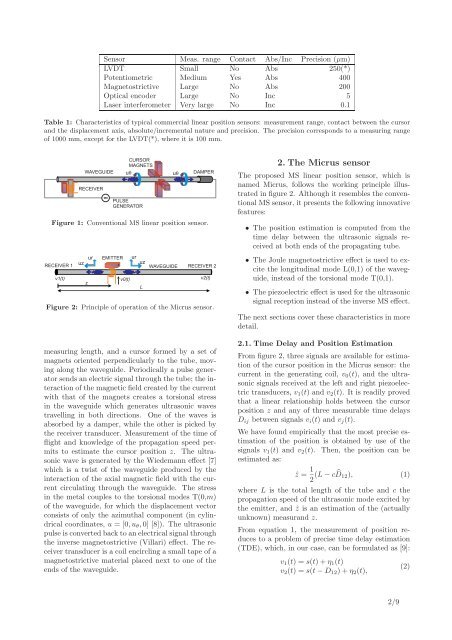
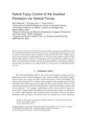
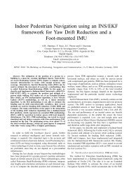
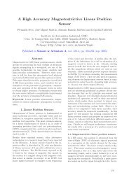
<strong>Sensor</strong> Meas. range Contact Abs/Inc Precision (µm)LVDT Small No Abs 250(*)Potentiometric Medium Yes Abs 400<strong>Magnetostrictive</strong> Large No Abs 200Optical encoder Large No Inc 5Laser interferometer Very large No Inc 0.1Table 1: Characteristics of typical commercial linear position sensors: measurement range, contact between the cursorand the displacement axis, absolute/incremental nature and precision. The precision corresponds to a measuring rangeof 1000 mm, except for the LVDT(*), where it is 100 mm.WAVEGUIDERECEIVERCURSORMAGNETSuPULSEGENERATORuDAMPERFigure 1: Conventional MS linear position sensor.ur EMITTER urRECEIVER 1uzuzWAVEGUIDE RECEIVER 2v1(t)zv0(t)Lv2(t)Figure 2: Principle of operation of the Micrus sensor.measuring length, and a cursor formed by a set ofmagnets oriented perpendicularly to the tube, movingalong the waveguide. Periodically a pulse generatorsends an electric signal through the tube; the interactionof the magnetic field created by the currentwith that of the magnets creates a torsional stressin the waveguide which generates ultrasonic wavestravelling in both directions. One of the waves isabsorbed by a damper, while the other is picked bythe receiver transducer. Measurement of the time offlight and knowledge of the propagation speed permitsto estimate the cursor position z. The ultrasonicwave is generated by the Wiedemann effect [7]which is a twist of the waveguide produced by theinteraction of the axial magnetic field with the currentcirculating through the waveguide. The stressin the metal couples to the torsional modes T(0,m)of the waveguide, for which the displacement vectorconsists of only the azimuthal component (in cylindricalcoordinates, u = [0,u θ ,0] [8]). The ultrasonicpulse is converted back to an electrical signal throughthe inverse magnetostrictive (Villari) effect. The receivertransducer is a coil encircling a small tape of amagnetostrictive material placed next to one of theends of the waveguide.2. The Micrus sensorThe proposed MS linear position sensor, which isnamed Micrus, follows the working principle illustratedin figure 2. Although it resembles the conventionalMS sensor, it presents the following innovativefeatures:• The position estimation is computed from thetime delay between the ultrasonic signals receivedat both ends of the propagating tube.• The Joule magnetostrictive effect is used to excitethe longitudinal mode L(0,1) of the waveguide,instead of the torsional mode T(0,1).• The piezoelectric effect is used for the ultrasonicsignal reception instead of the inverse MS effect.The next sections cover these characteristics in moredetail.2.1. Time Delay and <strong>Position</strong> EstimationFrom figure 2, three signals are available for estimationof the cursor position in the Micrus sensor: thecurrent in the generating coil, v 0 (t), and the ultrasonicsignals received at the left and right piezoelectrictransducers, v 1 (t) and v 2 (t). It is readily provedthat a linear relationship holds between the cursorposition z and any of three measurable time delaysD ij between signals v i (t) and v j (t).We have found empirically that the most precise estimationof the position is obtained by use of thesignals v 1 (t) and v 2 (t). Then, the position can beestimated as:ẑ = 1 2 (L − c ̂D 12 ), (1)where L is the total length of the tube and c thepropagation speed of the ultrasonic mode excited bythe emitter, and ẑ is an estimation of the (actuallyunknown) measurand z.From equation 1, the measurement of position reducesto a problem of precise time delay estimation(TDE), which, in our case, can be formulated as [9]:v 1 (t) = s(t) + η 1 (t)v 2 (t) = s(t − D 12 ) + η 2 (t),(2)2/9
where s(t) is the excitation signal in the cursorcoil, and η 1 and η 2 are the respective contaminatingnoises, which we will assume to be Gaussian anduncorrelated to each other and the signals. In theseconditions, it can be proved that the best estimationof the time delay ̂D 12 is yielded by the value thatmaximizes the correlation of signals:∫̂D 12 = max arg{ ̂R 12 (τ) = v 1 (t)v 2 (t − τ)dt}. (3)The Cramér-Rao lower bound (CRLB) [10] setsa limit on the maximum accuracy which can beachieved in the estimation of the time delay fromthe set of equations 2. The standard deviation σ D ofthe estimation of the delay ̂D is:σD 2 1≥16π 2 BTf0 2 (4)SNR,a result which is applicable in the case of narrowbandsignals with central frequency f 0 , and spectra containedin the interval |f| ∈ [f 0 −B,f 0 +B], where thebandwidth B is small with respect to f 0 . Likewise,the (linear) SNR must be high enough for unambiguousdetermination of the peak of the correlationR 12 (τ) [11]. The observation time, T, is, in practice,equal to the duration of the signal s(t).Another important nuance for the TDE process isthat we will actually work with sampled versionsv 1 [n] = v 1 (nt s ) and v 2 [n] = v 2 (nt s ) of the signalsin equation 2 (t s is the sampling time). If welimit the precision in the estimation of the correlationpeak to one sampling interval, the error committedcan be as high as ±t s /2. For example, fora sampling frequency of f s = 2 MHz, and takingc ≃ 5 µm/ns in equation 1, the position error isbounded by σ z = 600 µm, which is clearly too highfor a MS sensor.One method to estimate the time delay D 12 withsubsample precision consists in fitting an analyticalcurve to the three samples closest to the discretemaximum [12] (note that this requires a minimumsampling frequency f s > 6f 0 in order to have at leastthree points in the positive semi-cycle of the correlationvector). The proper analytical curve to be fitteddepends on the waveform s(t) used for excitation ofthe ultrasonic signals. In the Micrus sensor we haveemployed a sine train modulated by a Hanning window:[1 − cos( 2πtT ) ][S H (t) − S H (t − T)] sinω 0 t,s(t) = 1 2(5)where S H (t) is Heaviside’s step function, T =n cyc /f 0 is the total signal length, and n cyc is thenumber of cycles of the signal. This waveform doesa good job in producing a finite duration signal withits energy contained in a small bandwidth.For the signal of equation 5, the correlation takes acosine shape near the peak; thus, an improved estimationof the delay is obtained by fitting the followingfunction:R[m] = acos(bm + c), (6)to the discrete maximum m max and its neighboringpoints. The improved time delay is estimated as:with:̂D cos = (m max − c b )t s, (7)cos b = ̂R[m max − 1] + ̂R[m max + 1]2 ̂R[m max ]tan c = ̂R[m max − 1] − ̂R[m max + 1]2 ̂R[m.max ]sin b2.2. Selection of the propagating mode(8)A waveguide with cylindrical symmetry can supportthree families of modes: torsional (denoted T(0,m)),longitudinal (L(0,m)) and flexural (F(n,m)) [8]. Asthe index n stands for the order of symmetry aroundthe z axis, the torsional and longitudinal modes areaxisymmetric (n = 0), while the flexural modes areasymmetric. The index m is used to order the propagatingmodes which can coexist in a family for agiven operating frequency. In general, in any applicationwhich involves ultrasonic waves in solids,exploitation of a single propagating mode is recommended[13].Ultrasonic signals travelling in a waveguide are subjectto the phenomenon of dispersion, which is thevariation of the phase and group speeds of the propagatingwaves with frequency. The theoretical dispersioncurves in the low frequency range for the torsional,longitudinal and first two families of flexuralmodes are computed with the PCDISP software describedin reference [14] and shown in figure 3.It can be acknowledged from the figure that the modeT(0,1) has the unique feature of being free from dispersiveeffects. This is one reason that leads to itsuse in the commercial MS sensors that we saw in section1. In the Micrus sensor, however, we are interestedin exploring the possibilities of using the fasterpropagating first longitudinal mode L(0,1) for positionmeasurement. With a new design of the emitterit is possible to obtain high transduction efficiency inthe generation and reception processes, achieving theSNR required by equation 4 for accurate estimationof the time delay. For the L(0,1) mode, the displacementvector has two nonzero entries u = [u r ,0,u z ];3/9