A High Accuracy Magnetostrictive Linear Position Sensor
A High Accuracy Magnetostrictive Linear Position Sensor
A High Accuracy Magnetostrictive Linear Position Sensor

You also want an ePaper? Increase the reach of your titles
YUMPU automatically turns print PDFs into web optimized ePapers that Google loves.
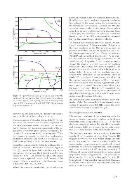
Phase speed (m/s)Group speed (m/s)80007000600050004000300020001000(a)F(1,1)F(2,1)L(0,1)T(0,1)F(1,2)L(0,2)00 50 100 150 200 250 300Frequency (kHz)600050004000300020001000(b)F(1,1)F(2,1)T(0,1)L(0,1)F(1,2)L(0,2)00 50 100 150 200 250 300Frequency (kHz)Figure 3: (a) Phase and (b) group speed curves for thetorsional T(0,m), longitudinal L(0,m) and first two flexuralmodes, F(1,m) and F(2,m), existing in the frequencyrange 0-300 kHz, computed with PCDISP. The tube datais given in section 3.1.however, at low frequencies, the radial component ismuch smaller than the axial one, u r ≪ u z .One consequence of choosing the mode L(0,1) for operationof our sensor is that we need to quantify theeffects of dispersion, unlike the case of the torsionalmode. Because the frequency components of the signaltravel at different phase speeds, the signal is distortedas it propagates along the waveguide. Whenthose signals are used in the time delay and positionestimation processes, the result is a systematic (i.e.,position dependent) error in the measurement.Several precautions can be taken to minimize the effectsof dispersion. The width of the flat region ofthe L(0,1) curve in figure 3 depends inversely on thethickness of the tube, so the thinnest available tubeshould be used. The excitation signal s(t) shouldhave a narrow spectral content, and the central frequencyf 0 lie in a point where the dispersion curveis relatively flat (dc ph /dω ≃ 0).Where dispersion is unavoidable, theoretical or empiricalknowledge of the wavenumber-frequency relationship,ξ(ω), can be used to compensate the distortionsuffered by the signal during the propagation inthe waveguide. For example, Gorham and Wu [15]were able to restore the original shape of stress pulsescaused by impact of steel spheres in pressure bars.Wilcox [16] has developed an optimized algorithmbased on use of the FFT which could be employedfor real time correction of dispersive effects.To check if these methods are really needed, we performedsimulations of the propagation of signals inthe tube employed in the Micrus system, and theposition estimation method of equation 1, for a totaldisplacement range of 1 m. Using the softwarePCDISP and the method described in [17], we studiedthe influence of two design parameters of thewaveform s(t) of equation 5: the central frequencyf 0 and the number of cycles n cyc , on the positionestimation. The results are shown in figure 4 (thephysical data for the transmitting tube is given insection 3.1. As expected, the position error increaseswith frequency, as the dispersion curve ofmode L(0,1) in figure 3 gets steeper and closer tothe cutting frequency of mode L(0,2). The positionerror decreases with growing signal length (narrowerspectral content), becoming lower than 1 µmfor n cyc > 4 cycles. This is very convenient, becauseit allows to use relatively short (temporal orspatial) excitation signals, and obtain a longer measuringrange for a given tube size.As a conclusion of the simulation process, active correctionof the dispersion effects is not needed for operatingfrequencies below 100 kHz, unless the errordue to other sources is inferior to 2 µm.2.3. <strong>Magnetostrictive</strong> EmitterThe emitter transducer of the Micrus system is designedto produce maximum coupling to the chosenultrasonic mode (longitudinal L(0,1)). To this endthe Joule magnetostrictive effect (in which the staticand dynamic fields are arranged in the axial direction[7]) is used instead of the Wiedemann effect.The emitter transducer, shown in figure 5, consistsmainly of two elements. A set of four Alcomax IIImagnets provide a bias field which brings the partof the tube under the cursor to a known state in themagnetization curve, reducing hysteretic effects andincreasing measurement repeatability. In the centralregion, an excitation coil (10 mm long, consisting of60 turns of copper wire), creates the dynamic signalresponsible of the MS generation. The total field isthen given by H(z) = H 0 + H 1 expj2πf 0 t, with H 1being about 10 times smaller in magnitude than H 0 ,in order to reduce harmonics created by the nonlineargeneration of ultrasound.4/9