Activity Report 2004-2008 (3,5 MB â 1st - IEMN
Activity Report 2004-2008 (3,5 MB â 1st - IEMN
Activity Report 2004-2008 (3,5 MB â 1st - IEMN
- No tags were found...

You also want an ePaper? Increase the reach of your titles
YUMPU automatically turns print PDFs into web optimized ePapers that Google loves.
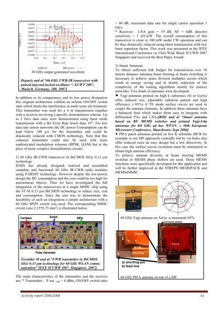
= 40 dB, maximum data rate for single carrier operation 1Gb/s.* Receiver: LNA gain = 19 dB, NF = 6dB, detectorsensitivity = 1 mV/µW. The overall consumption of thistransceiver is close to 300 mW under CW operation and canbe thus drastically reduced using burst transmission with lowburst repetition factor. This work was presented at the IEEEInternational Conference on Ultra Wide Band, ICUWB 2007Singapore and received the Best Paper Award.30 GHz output generated waveformDeparis and al “60-GHz UWB-IR transceiver withpulsed-injected locked oscillator “. ECWT 2007,Munich, Germany, 280, 2007]In addition to its compactness and its low power dissipationthis original architecture exhibits an infinite ON/OFF switchratio which limits the interference in multi users environment.This transmitter was used for a 4 m transmission togetherwith a receiver involving a specific demodulation scheme. Upto 2 Gb/s data rates were demonstrated using burst modetransmission with a Bit Error Rate lower than 10 -6 . For lowdata rate sensor networks the DC power Consumption can bekept below 100 µw for the transmitter and could bedrastically reduced with CMOS technology. Note that thiscoherent transmitter could also be used with moresophisticated modulation schemes (BPSK, QAM) but at theprice of more complex demodulation circuits.2) 60 GHz IR-UWB transceiver in BiCMOS SiGe 0.13 µmtechnology<strong>IEMN</strong> has already designed, realized and assembledcomplete and functional 60 GHz IR-UWB radio modulesusing P-HEMT technology. However despite the low-powerdesign the DC consumption and the cost could be too high forautonomous objects. Thus we have investigated the fullintegration of the transceivers in a single MMIC chip usingthe ST-M 0.13 µm BiCMOS technology to reduce size, costand consumption. Since the aim was to demonstrate thefeasibility of such an integration a simple architecture with a60 GHz SPDT switch was used. The corresponding MMICcircuit (size 2.15*0.75 mm 2 ) is illustrated below.3) Smart AntennasTo obtain sufficient link budget for transmission over 10meters distance antennas beam forming or beam switching isnecessary to achieve space division multiples access whichresult in energy saving and in drastic reduction of thecomplexity of the routing algorithms mainly for sensorsnetworks. Two kinds of antennas were developed: Yagi antennas printed on high k substrates (Si or GaAs)offer reduced size, adjustable radiation pattern and highefficiency (>85%) if TE mode surface waves are used tocouple the antenna elements. In addition these antennas havea balanced feed which makes them easy to integrate withdifferential PAs and LNA.[BOE and al “Smart antennabased on RF MEMS switches and printed Yagi-Udaantennas for 6O GHz ad hoc WPAN. » 36th EuropeanMicrowave Conference, Manchester, Sept 2006] PIFA patch antennas printed on low K substrate (BCB forexample in our SIP approach) vertically fed by via holes alsooffer reduced sizes an easy design but a low directivity. Inthis case the surface waves excitation must be minimized toobtain high antenna efficiency.To achieve antenna diversity or beam steering MEMSswitches or MEMS phase shifters are used. These MEMSfunctions were specifically developed for this application andwill be further improved in the STREPS MEMSPACK andMEMS4MMIC.27030024033010-10-20E co-polar mesuréE co-polar simulé21000301506012090OscillatorSwitchMPA60 GHz Yagi antenna on AsGa. η measured=85%180Ground planeGroundplanePatchLayout de l’émetteurTaille du circuit : 2 x 0,75 mm²a) b)BCBPatchPulse GeneratorAMicrostripDevulder M and al “UWB transmitter in BiCMOSSiGe 0.13 µm technology for 60 GHz WLAN comm.-unication” IEEE ICUWB 2007, Singapore, 2007].a) shorting-pinb) feed lineAMicrostripBCBThe main characteristics of the transmitter and the receiverare: * Transmitter : P out -1dB = 8 dBm, ON/OFF switch ratio60 GHz PIFA antenna on top of a SIP<strong>Activity</strong> report <strong>2004</strong>/<strong>2008</strong> 61