buck quasi-resonant zvs converter with linear feedback control
buck quasi-resonant zvs converter with linear feedback control
buck quasi-resonant zvs converter with linear feedback control

You also want an ePaper? Increase the reach of your titles
YUMPU automatically turns print PDFs into web optimized ePapers that Google loves.
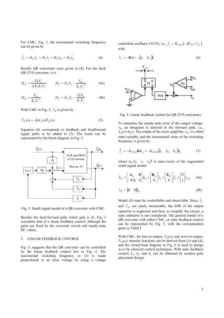
For CMC, Fig. 2, the incremental switching frequencycan be given byf ˆ = H vˆ+ H vˆ+ H vˆ+ H iˆ(4)sEEIIOOL L<strong>control</strong>led oscillator (VCO), i.e., fˆK ( −βvˆv )<strong>with</strong>= ,s VCO O + ˆxv = −Kxˆ= −[ k k ]xˆ(6)ˆ x1 2Results QR <strong>converter</strong>s were given in [4]. For the <strong>buck</strong>QR-ZVS <strong>converter</strong>, it isHE=2LFsA R K VlssIHIV= K I Fs−(4a)KO2sVIH =OKVO2sVIHL2LFs= K LFs−(4b)K VsIWith CMC in Fig. 2, vˆEis given byVˆ( s)= −βA( s)Vˆ( s)(5)EvOEquation (4) corresponds to <strong>feedback</strong> and feedforwardsignal paths to be added to (3). The result can berepresented by the block diagram in Fig. 3.Fig. 4: Linear <strong>feedback</strong> <strong>control</strong> for QR-ZVS <strong>converter</strong>s.To minimise the steady-state error of the output voltage,v O , an integrator is inserted in the forward path, i.e.,A v (s)=k 3 /s. The output of the error amplifier, v E , is a thirdstate-variable, and the incremental value of the switchingfrequency is given by,fˆsa[ k 1 k 2 k 3 ] xˆa= −KKxˆ= −K(7)VCOVCOwhere x a =[i L v C v E ] t is state-vector of the augmentedsmall-signal model:⎡ A p 0⎤⎡Bp ⎤ ⎡Ep ⎤ 0ˆ.ˆ vˆI fˆ⎡ ⎤x & a = ⎢a + s + vˆref0⎥ x + ⎢0⎥ ⎢0⎥ ⎢1⎥ (8a)⎣−Cβ⎦ ⎣ ⎦ ⎣ ⎦ ⎣ ⎦[ C 0] xˆav ˆ =(8b)OFig. 3: Small-signal model of a QR <strong>converter</strong> <strong>with</strong> CMC.Besides the feed-forward path, which gain is H I , Fig. 3resembles that of a <strong>linear</strong> <strong>feedback</strong> <strong>control</strong>, although thegains are fixed by the <strong>converter</strong> circuit and steady-stateDC values.3. LINEAR FEEDBACK CONTROLFig. 3, suggests that the QR <strong>converter</strong> can be <strong>control</strong>ledby the <strong>linear</strong> <strong>feedback</strong> <strong>control</strong> law in Fig. 4. Theincremental switching frequency in (3) is madeproportional to an error voltage by using a voltageModel (8) must be <strong>control</strong>lable and observable. Since î Land vˆO are easily measurable, the ESR of the outputcapacitor is neglected and thus, to simplify the circuit, astate estimator is not considered. The general model of aQR <strong>converter</strong> <strong>with</strong> either CMC, or state <strong>feedback</strong> <strong>control</strong>can be represented by Fig. 5, <strong>with</strong> the correspondentgains in Table I.With CMC, the line-to-output, T IO (s), and error-to-output,T EO (s), transfer functions can be derived from (3) and (4),and the closed-loop diagram in Fig. 6 is used to designA v (s) by classical <strong>control</strong> techniques. With state <strong>feedback</strong><strong>control</strong>, k 1 , k 2 , and k 3 can be obtained by modern poleplacement design.3
![Conceitos transmissao de dados .Sinais[.pdf]](https://img.yumpu.com/50982145/1/190x146/conceitos-transmissao-de-dados-sinaispdf.jpg?quality=85)
![Packages e interfaces[.pdf]](https://img.yumpu.com/50629553/1/190x134/packages-e-interfacespdf.jpg?quality=85)