buck quasi-resonant zvs converter with linear feedback control
buck quasi-resonant zvs converter with linear feedback control
buck quasi-resonant zvs converter with linear feedback control

Create successful ePaper yourself
Turn your PDF publications into a flip-book with our unique Google optimized e-Paper software.
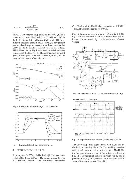
s + 1506A v ( s)= 20750(11)s(s + 4150)In Fig. 7 we compare loop gains of the <strong>buck</strong> QR-ZVS<strong>converter</strong>: (1) <strong>with</strong> CMC and (11); (2) <strong>with</strong> the LQR inTable III for ρ=0.01. Although CMC and LQR havedifferent <strong>feedback</strong> gains in Fig. 5, the LQR may presentsimilar closed-loop performances to those obtained byCMC, due to the similar dominant poles in closed-loop.This is illustrated by Fig. 8, where theoretical closed-loopresponses of the <strong>buck</strong> QR-LQR <strong>converter</strong>, <strong>with</strong> differentgains, are compared <strong>with</strong> that obtained by CMC, for thesame sudden change of the reference.R L =160mΩ and R C =80mΩ where measured at 100 kHz.The LQR was implemented for ρ=0.01.Fig. 10 shows some experimental waveforms for R=2.2Ω.Fig. 11 shows perturbations of the output voltage and theinductor current caused by a variation in the referencevoltage.Fig. 9: Experimental <strong>buck</strong> QR-ZVS <strong>converter</strong> <strong>with</strong> LQR.Fig. 7: Loop gains of the <strong>buck</strong> QR-ZVS <strong>converter</strong>.Fig. 10: Experimental waveforms (V I =15.5V; V O =5V).Fig. 8: Predicted closed-loop responses of v O .5. EXPERIMENTAL RESULTSA prototype of a 25W, 1 MHz, <strong>buck</strong> QR-ZVS <strong>converter</strong><strong>with</strong> LQR is shown in Fig. 9. The parameters are those inthe previous section. The equivalent resistencesThe closed-loop small-signal model <strong>with</strong> LQR can beobtained by replacing (7) in (8). The resulting equation,<strong>with</strong> v ˆI = 0 , was solved numerically (<strong>with</strong> MATLAB)for the experimental values of the reference voltage inFig. 11. The theoretical result is shown in Fig. 12 and itpresents a very good agreement <strong>with</strong> the experimentalvalue of the output voltage (Fig. 11).5
![Conceitos transmissao de dados .Sinais[.pdf]](https://img.yumpu.com/50982145/1/190x146/conceitos-transmissao-de-dados-sinaispdf.jpg?quality=85)
![Packages e interfaces[.pdf]](https://img.yumpu.com/50629553/1/190x134/packages-e-interfacespdf.jpg?quality=85)