buck quasi-resonant zvs converter with linear feedback control
buck quasi-resonant zvs converter with linear feedback control
buck quasi-resonant zvs converter with linear feedback control

You also want an ePaper? Increase the reach of your titles
YUMPU automatically turns print PDFs into web optimized ePapers that Google loves.
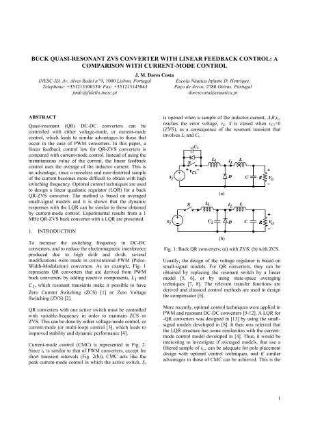
BUCK QUASI-RESONANT ZVS CONVERTER WITH LINEAR FEEDBACK CONTROL: ACOMPARISON WITH CURRENT-MODE CONTROLJ. M. Dores CostaINESC-ID, Av. Alves Redol nº 9, 1000 Lisbon, Portugal Escola Náutica Infante D. Henrique,Telephone: +351213100350/ Fax: +351213145843Paço de Arcos, 2780 Oeiras, Portugaljmdc@fidelio.inesc.ptdorescosta@enautica.ptABSTRACTQuasi-<strong>resonant</strong> (QR) DC-DC <strong>converter</strong>s can be<strong>control</strong>led <strong>with</strong> either voltage-mode, or current-mode<strong>control</strong>, which leads to similar advantages to those thatoccur in the case of PWM <strong>converter</strong>s. In this paper, a<strong>linear</strong> <strong>feedback</strong> <strong>control</strong> law for QR-ZVS <strong>converter</strong>s iscompared <strong>with</strong> current-mode <strong>control</strong>. Instead of using theinstantaneous value of the current, the <strong>linear</strong> <strong>feedback</strong><strong>control</strong> uses the average of the inductor current. This isan advantage, since a noiseless and non-distorted sampleof the current becomes more difficult to obtain <strong>with</strong> highswitching frequency. Optimal <strong>control</strong> techniques are usedto design a <strong>linear</strong> quadratic regulator (LQR) for a <strong>buck</strong>QR-ZVS <strong>converter</strong>. The method is based on averagedsmall-signal models and it is shown that the dynamicresponses <strong>with</strong> the LQR can be similar to those obtainedby current-mode <strong>control</strong>. Experimental results from a 1MHz QR-ZVS <strong>buck</strong> <strong>converter</strong> <strong>with</strong> a LQR are presented.1. INTRODUCTIONTo increase the switching frequency in DC-DC<strong>converter</strong>s, and to reduce the electromagnetic interferenceproduced due to high di/dt and dv/dt, severalmodifications were made in conventional PWM (Pulse-Width-Modulation) <strong>converter</strong>s. As an example, Fig. 1represents QR <strong>converter</strong>s that are derived from PWM<strong>buck</strong> <strong>converter</strong>s by adding reactive components, L 1 andC 1 , which <strong>resonant</strong> transients make it possible to haveZero Current Switching (ZCS) [1] or Zero VoltageSwitching (ZVS) [2].QR <strong>converter</strong>s <strong>with</strong> one active switch must be <strong>control</strong>led<strong>with</strong> variable-frequency in order to maintain ZCS orZVS. This can be done by either voltage-mode <strong>control</strong>, orcurrent-mode (or multi-loop) <strong>control</strong> [3], which leads toimproved stability and dynamic performance [4].Current-mode <strong>control</strong> (CMC) is represented in Fig. 2.Since i L is similar to that of PWM <strong>converter</strong>s, except forshort transient intervals (Fig. 2(b)), CMC acts like thepeak current-mode <strong>control</strong> in which the active switch, S,is opened when a sample of the inductor-current, A l R s i L ,reaches the error voltage, v E . S is closed when v C1 =0(ZVS), as a consequence of the <strong>resonant</strong> transient thatinvolves L l and C l .(a)(b)Fig. 1: Buck QR <strong>converter</strong>s; (a) <strong>with</strong> ZVS; (b) <strong>with</strong> ZCS.Usually, the design of the voltage regulator is based onsmall-signal models. For QR <strong>converter</strong>s, they can beobtained by replacing the <strong>resonant</strong> switch by a <strong>linear</strong>model [5, 6], or by using state-space averagingtechniques [7, 8]. The relevant transfer functions arederived and classical <strong>control</strong> methods are used to designthe compensator [6].More recently, optimal <strong>control</strong> techniques were applied toPWM and <strong>resonant</strong> DC-DC <strong>converter</strong>s [9-12]. A LQR for-QR <strong>converter</strong>s was designed in [13] by using the smallsignalmodels developed in [8]. It then was referred thatthe LQR structure has some similarities <strong>with</strong> the currentmode<strong>control</strong> model developed in [4]. Thus, it would beinteresting to investigate if averaged models, that use afiltered sample of i L ,, can be adequate for pole placementdesign <strong>with</strong> optimal <strong>control</strong> techniques, and if similaradvantages to those of CMC can be achieved. This is the1
For CMC, Fig. 2, the incremental switching frequencycan be given byf ˆ = H vˆ+ H vˆ+ H vˆ+ H iˆ(4)sEEIIOOL L<strong>control</strong>led oscillator (VCO), i.e., fˆK ( −βvˆv )<strong>with</strong>= ,s VCO O + ˆxv = −Kxˆ= −[ k k ]xˆ(6)ˆ x1 2Results QR <strong>converter</strong>s were given in [4]. For the <strong>buck</strong>QR-ZVS <strong>converter</strong>, it isHE=2LFsA R K VlssIHIV= K I Fs−(4a)KO2sVIH =OKVO2sVIHL2LFs= K LFs−(4b)K VsIWith CMC in Fig. 2, vˆEis given byVˆ( s)= −βA( s)Vˆ( s)(5)EvOEquation (4) corresponds to <strong>feedback</strong> and feedforwardsignal paths to be added to (3). The result can berepresented by the block diagram in Fig. 3.Fig. 4: Linear <strong>feedback</strong> <strong>control</strong> for QR-ZVS <strong>converter</strong>s.To minimise the steady-state error of the output voltage,v O , an integrator is inserted in the forward path, i.e.,A v (s)=k 3 /s. The output of the error amplifier, v E , is a thirdstate-variable, and the incremental value of the switchingfrequency is given by,fˆsa[ k 1 k 2 k 3 ] xˆa= −KKxˆ= −K(7)VCOVCOwhere x a =[i L v C v E ] t is state-vector of the augmentedsmall-signal model:⎡ A p 0⎤⎡Bp ⎤ ⎡Ep ⎤ 0ˆ.ˆ vˆI fˆ⎡ ⎤x & a = ⎢a + s + vˆref0⎥ x + ⎢0⎥ ⎢0⎥ ⎢1⎥ (8a)⎣−Cβ⎦ ⎣ ⎦ ⎣ ⎦ ⎣ ⎦[ C 0] xˆav ˆ =(8b)OFig. 3: Small-signal model of a QR <strong>converter</strong> <strong>with</strong> CMC.Besides the feed-forward path, which gain is H I , Fig. 3resembles that of a <strong>linear</strong> <strong>feedback</strong> <strong>control</strong>, although thegains are fixed by the <strong>converter</strong> circuit and steady-stateDC values.3. LINEAR FEEDBACK CONTROLFig. 3, suggests that the QR <strong>converter</strong> can be <strong>control</strong>ledby the <strong>linear</strong> <strong>feedback</strong> <strong>control</strong> law in Fig. 4. Theincremental switching frequency in (3) is madeproportional to an error voltage by using a voltageModel (8) must be <strong>control</strong>lable and observable. Since î Land vˆO are easily measurable, the ESR of the outputcapacitor is neglected and thus, to simplify the circuit, astate estimator is not considered. The general model of aQR <strong>converter</strong> <strong>with</strong> either CMC, or state <strong>feedback</strong> <strong>control</strong>can be represented by Fig. 5, <strong>with</strong> the correspondentgains in Table I.With CMC, the line-to-output, T IO (s), and error-to-output,T EO (s), transfer functions can be derived from (3) and (4),and the closed-loop diagram in Fig. 6 is used to designA v (s) by classical <strong>control</strong> techniques. With state <strong>feedback</strong><strong>control</strong>, k 1 , k 2 , and k 3 can be obtained by modern poleplacement design.3
−1taK = ρ E P(10)where P is the solution of the Riccati's equation ,t−1ta aa a =A P + PA − ρ PE E P + Q 0(10a)<strong>with</strong>⎡ Ap0⎤⎡K Ep⎤A a = ⎢ ⎥ E = VCOa⎣-βC0⎢ ⎥⎦⎣ 0 ⎦(10b)Fig. 5: Small-signal model of a QR <strong>converter</strong> <strong>with</strong> statevariable<strong>feedback</strong>.Table I: Gains for Fig. 5.Control lawCurrent-mode State <strong>feedback</strong>g 1 H L -k 1 .K VCO /A l R sg 2 H O /β -k 2 .K VCO /βg 3 H E K VCOg 4 H I 0A v (s)s + zAs( s + p)k − 3s⎡αI0⎤We will use Q = ⎢ ⎥ , where I is a 2x2 identity⎣ 0 q ⎦matrix; q must be large enough for the steady-state errorto be zero, and ρ must be small for a faster response.4. SIMULATION RESULTSTo compare the LQR <strong>with</strong> CMC, we consider the <strong>buck</strong>QR-ZVS <strong>converter</strong> in Fig 1(a) <strong>with</strong> an half-wave switch,and the following parameters: L 1 =1.3µH, C 1 =4.9nFR=2Ω, L=72µH, C=1000µF. The equivalent lossresistences of L and C are R L =160mΩ and R C =80mΩ,respectively. Nominal voltages are V I =15V, V O =5V;K VCO =170kHz/V, A l R s =1, and β=0.5.The resulting gains for CMC, are listed in Table II.Table II: Results for CMC (eq. (4)).H L H O H E H I1.01 10 7 -2.80 10 4 -1.02 10 7 4.70 10 4Different LQR can be obtained if different weightingcoefficients in (9) are used. With α=0.1, and q=10 8 , someresults for K are listed in Table III.Fig. 6: Closed-loop block diagram.For a LQR, K in (7) is calculated in order to minimise aquadratic cost function,J∞=∫( T2a a E d0x ˆ Qx ˆ + ρvˆ ) t(9)where Q is a symmetric positive-definite matrix, and ρ isa positive scalar that have a strong influence on theclosed-loop poles; vˆE is the error voltage in Fig. 5. Theoptimal solution of (9) is given byTable III: LQR gains (α=0.1, q=10 8 ).LQR gainsρ k 1 k 2 k 30.01 -2.42 -13.73 10 50.1 -0.53 -5.09 3.16 10 41 -0.12 -0.15 10 4With CMC, T EO (s) was calculated in order to obtain 50ºphase margin when the crossover frequency is 2500 rad/s.The result is,4
s + 1506A v ( s)= 20750(11)s(s + 4150)In Fig. 7 we compare loop gains of the <strong>buck</strong> QR-ZVS<strong>converter</strong>: (1) <strong>with</strong> CMC and (11); (2) <strong>with</strong> the LQR inTable III for ρ=0.01. Although CMC and LQR havedifferent <strong>feedback</strong> gains in Fig. 5, the LQR may presentsimilar closed-loop performances to those obtained byCMC, due to the similar dominant poles in closed-loop.This is illustrated by Fig. 8, where theoretical closed-loopresponses of the <strong>buck</strong> QR-LQR <strong>converter</strong>, <strong>with</strong> differentgains, are compared <strong>with</strong> that obtained by CMC, for thesame sudden change of the reference.R L =160mΩ and R C =80mΩ where measured at 100 kHz.The LQR was implemented for ρ=0.01.Fig. 10 shows some experimental waveforms for R=2.2Ω.Fig. 11 shows perturbations of the output voltage and theinductor current caused by a variation in the referencevoltage.Fig. 9: Experimental <strong>buck</strong> QR-ZVS <strong>converter</strong> <strong>with</strong> LQR.Fig. 7: Loop gains of the <strong>buck</strong> QR-ZVS <strong>converter</strong>.Fig. 10: Experimental waveforms (V I =15.5V; V O =5V).Fig. 8: Predicted closed-loop responses of v O .5. EXPERIMENTAL RESULTSA prototype of a 25W, 1 MHz, <strong>buck</strong> QR-ZVS <strong>converter</strong><strong>with</strong> LQR is shown in Fig. 9. The parameters are those inthe previous section. The equivalent resistencesThe closed-loop small-signal model <strong>with</strong> LQR can beobtained by replacing (7) in (8). The resulting equation,<strong>with</strong> v ˆI = 0 , was solved numerically (<strong>with</strong> MATLAB)for the experimental values of the reference voltage inFig. 11. The theoretical result is shown in Fig. 12 and itpresents a very good agreement <strong>with</strong> the experimentalvalue of the output voltage (Fig. 11).5
the weighting factors, the dynamic performance can besimilar to that presented by current-mode <strong>control</strong>.Simulation and experimental results of a 1 MHz <strong>buck</strong>QR-ZVS <strong>converter</strong> confirmed the feasibility of themethod.7. REFERENCESFig. 11: Perturbations of v O and i L for the perturbation ofthe reference voltage.Fig. 12: Theoretical (1) and experimental (2) waveformsof v O for the perturbation of v re f in Fig. 11.6. CONCLUSIONSA <strong>linear</strong> <strong>feedback</strong> regulator was proposed to <strong>control</strong> QR-ZVS <strong>converter</strong>s. It was shown that it has somesimilarities <strong>with</strong> current-mode <strong>control</strong> and that it canleads to similar advantages.Optimal <strong>control</strong> techniques and small-signal models, thatare an extension of those of PWM <strong>converter</strong>s, were usedto design a LQR for QR <strong>converter</strong>s. Results of a <strong>buck</strong>QR-ZVS <strong>converter</strong> <strong>with</strong> a LQR show that, by choosing[1] K. H. Liu, R. Oruganti, F. C. Lee, "Quasi-<strong>resonant</strong><strong>converter</strong>s: topologies and characterisitics", IEEETrans. Power Electronics, vol. 2, pp. 62-71, January1987.[2] K. H. Liu, F. C. Lee, "Zero-voltage switchingtechnique in DC/DC <strong>converter</strong>s", IEEE Trans.Power Electronics, vol. 5, pp. 293-304, July 1990.[3] R. B. Ridley, W. A. Tabisz, F. C. Lee, V. Vorperian,"Multi-Loop Control for Quasi-ResonantConverters", IEEE Trans. on Power Electronics,vol. 6, January 1991, pp. 28-37.[4] J .M. F. Dores Costa, M. Medeiros Silva, "Smallsignalmodels and dynamic performance of <strong>quasi</strong><strong>resonant</strong><strong>converter</strong>s <strong>with</strong> current-mode <strong>control</strong>",IEEE PESC'94 Rec., pp. 821-829.[5] V. Vorpérien, R. Tymerski, F. C. Lee, "Equivalentcircuit models for <strong>resonant</strong> and PWM switches",IEEE Trans. Power Electronics, vol. 4, pp. 205-214,April 1989.[6] B. Baha, "The <strong>control</strong> of <strong>quasi</strong>-<strong>resonant</strong> <strong>converter</strong>s",Proc. EPE'93, pp. 304-309.[7] A. F. Witulski, R. W. Erickson, "Extension of statespaceaveraging to <strong>resonant</strong> switches and beyond",IEEE Trans. Power Electronics, vol. 5, pp. 98-109,January 1990.[8] J .M. F. Dores Costa, M. Medeiros Silva, "Smallsignalmodels of <strong>quasi</strong>-<strong>resonant</strong> <strong>converter</strong>s", IEEEISIE'97 Rec., pp. 258-262.[9] J. M. Carrasco, F. Gordillo, L. G. Franquelo, F. R.Rubio, "Control of <strong>resonant</strong> <strong>converter</strong>s using theLQG/LTR method", IEEE PESC'92 Rec., pp. 814-821.[10] Frank H. F. Leung, Peter K. S. Tam, C. K. Li, "The<strong>control</strong> of switching dc-dc <strong>converter</strong>s-A generalLQR problem", IEEE Trans. on IndustrialElectronics, vol. 38, pp. 65-71, February 1991.[11] Frank H. F. Leung, Peter K. S. Tam, C. K. Li, "Animproved LQR-based <strong>control</strong>ler for switching DC-DC <strong>converter</strong>s", IEEE Trans. on IndustrialElectronics, vol. 40, pp. 521-528, October 1993.[12] Cahit Gezgin, Bonnie S. Heck, Richard M. Bass,“Control Structure Optimization of a BoostConverter: An LQR Approach”, IEEE PESC'97Rec., pp. 901-907.6
![Conceitos transmissao de dados .Sinais[.pdf]](https://img.yumpu.com/50982145/1/190x146/conceitos-transmissao-de-dados-sinaispdf.jpg?quality=85)
![Packages e interfaces[.pdf]](https://img.yumpu.com/50629553/1/190x134/packages-e-interfacespdf.jpg?quality=85)