ADSP-219x/2191 DSP Hardware Reference, Introduction
ADSP-219x/2191 DSP Hardware Reference, Introduction
ADSP-219x/2191 DSP Hardware Reference, Introduction

You also want an ePaper? Increase the reach of your titles
YUMPU automatically turns print PDFs into web optimized ePapers that Google loves.
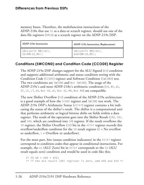
Differences from Previous <strong>DSP</strong>smemory buses. Therefore, the multifunction instructions of the<strong>A<strong>DSP</strong></strong>-218x that use SE as a data or scratch register, should use one of thedata file registers (DREG) as a scratch register on the <strong>A<strong>DSP</strong></strong>-<strong>219x</strong> <strong>DSP</strong>.<strong>A<strong>DSP</strong></strong>-218x InstructionSR=Lshift MR1(HI),SE=DM(I6,M5);<strong>A<strong>DSP</strong></strong>-<strong>219x</strong> Instruction (Replacement)SR=Lshift MR1(HI),AX0=DM(I6,M5);Conditions (SWCOND) and Condition Code (CCODE) RegisterThe <strong>A<strong>DSP</strong></strong>-<strong>219x</strong> <strong>DSP</strong> changes support for the ALU Signed (AS) conditionand supports additional arithmetic and status condition testing with theCondition Code (CCODE) register and Software Condition (SWCOND) test.The two conditions are SWCOND and Not SWCOND. The usage of the<strong>A<strong>DSP</strong></strong>-<strong>219x</strong>’s and most <strong>A<strong>DSP</strong></strong>-218x’s arithmetic conditions (EQ, NE, GE,GT, LE, LT, AV, Not AV, AC, Not AC, MV, Not MV) are compatible.The new Shifter Overflow (SV) condition of the <strong>A<strong>DSP</strong></strong>-<strong>219x</strong> architectureis a good example of how the CCODE register and SWCOND test work. The<strong>A<strong>DSP</strong></strong>-<strong>219x</strong> <strong>DSP</strong>’s Arithmetic Status (ASTAT) register contains a bit indicatingthe status of the shifter’s result. The shifter is a computational unitthat performs arithmetic or logical bitwise shifts on fields within a dataregister. The result of the operation goes into the Shifter Result (SR2, SR1,and SR0, which are combined into SR) register. If the result overflows theSR register, the Shifter Overflow (SV) bit in the ASTAT register records thisoverflow/underflow condition for the SR result register (0 = No overflowor underflow, 1 = Overflow or underflow).For the most part, bits (status condition indicators) in the ASTAT registercorrespond to condition codes that appear in conditional instructions. Forexample, the AZ (ALU Zero) bit in ASTAT corresponds to the EQ (ALUresult equals zero) condition and would be used in code like this:IF EQ AR = AX0 + AY0;/* if the ALU result (AR) register is zero, add AX0 and AY0 */1-26 <strong>A<strong>DSP</strong></strong>-<strong>219x</strong>/<strong>2191</strong> <strong>DSP</strong> <strong>Hardware</strong> <strong>Reference</strong>