PM CTP CAT M EA P 4 X 3 v01 | 2009-02-01 - Elion
PM CTP CAT M EA P 4 X 3 v01 | 2009-02-01 - Elion
PM CTP CAT M EA P 4 X 3 v01 | 2009-02-01 - Elion
- No tags were found...

Create successful ePaper yourself
Turn your PDF publications into a flip-book with our unique Google optimized e-Paper software.
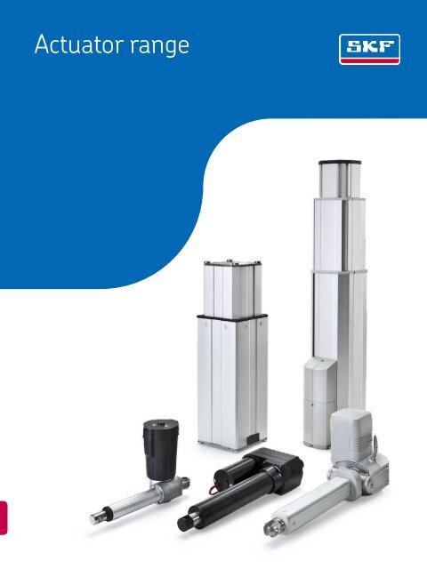
Actuator range
® SKF is a registered trademark of the SKF Group.© SKF Group <strong>2009</strong>The contents of this publication are the copyright of the publisher and may not be reproduced (even extracts) unless prior written permissionis granted. Every care has been taken to ensure the accuracy of the information contained in this publication but no liability can beaccepted for any loss or damage whether direct, indirect or consequential arising out of the use of the information contained herein.PUB MT/P1 10060 EN · October <strong>2009</strong>This publication supersedes publication 5322.Printed in Sweden on environmentally friendly paper.
Principles of actuator and pillar selection and application . . . . . . . . . . 91Telescopic pillars . . . . . . . . . . . . . . . . . . . . . . . . . . . . . . . . . . . . . . . . . 372Linear actuators . . . . . . . . . . . . . . . . . . . . . . . . . . . . . . . . . . . . . . . . . 1053Rotary actuators . . . . . . . . . . . . . . . . . . . . . . . . . . . . . . . . . . . . . . 299 . . .4Control units . . . . . . . . . . . . . . . . . . . . . . . . . . . . . . . . . . . . . . . 311 . . . . .5Hand, foot and desk switches . . . . . . . . . . . . . . . . . . . . . . . . . . . . . . . 3436Customized projects . . . . . . . . . . . . . . . . . . . . . . . . . . . . . . . . . . . . . . 3717Drive by wire . . . . . . . . . . . . . . . . . . . . . . . . . . . . . . . . . . . . . . . . . . . 3818Spare parts . . . . . . . . . . . . . . . . . . . . . . . . . . . . . . . . . . . . . . . . . . . . 38791
ContentsForeword . . . . . . . . . . . . . . . . . . . . . . . . . . . . . . . . . . . . . . . . . . 4SKF – the knowledge engineering company . . . . . . . . . . . . . . 61 Principles of actuator and pillar selection and application .... 9Linear actuator definition & type . . . . . . . . . . . . . . . . . . . . . . . . 10Definition . . . . . . . . . . . . . . . . . . . . . . . . . . . . . . . . . . . . . . . . 10Ball screw vs acme screw . . . . . . . . . . . . . . . . . . . . . . . . . . . . 11Performance considerations . . . . . . . . . . . . . . . . . . . . . . . . . . . . 11Limit switch . . . . . . . . . . . . . . . . . . . . . . . . . . . . . . . . . . . . . . 11Hall sensors . . . . . . . . . . . . . . . . . . . . . . . . . . . . . . . . . . . . . . 11Potentiometer . . . . . . . . . . . . . . . . . . . . . . . . . . . . . . . . . . . . 11Friction clutch . . . . . . . . . . . . . . . . . . . . . . . . . . . . . . . . . . . . . 11Ball detent clutch . . . . . . . . . . . . . . . . . . . . . . . . . . . . . . . . . . 11Back-up nut . . . . . . . . . . . . . . . . . . . . . . . . . . . . . . . . . . . . . . 11Slip-stick effect . . . . . . . . . . . . . . . . . . . . . . . . . . . . . . . . . . . . 11Selection criteria . . . . . . . . . . . . . . . . . . . . . . . . . . . . . . . . . . . . 12Force . . . . . . . . . . . . . . . . . . . . . . . . . . . . . . . . . . . . . . . . . . . 12Load capacity . . . . . . . . . . . . . . . . . . . . . . . . . . . . . . . . . . . . . 12Speed . . . . . . . . . . . . . . . . . . . . . . . . . . . . . . . . . . . . . . . . . . . 12Stroke and retracted length . . . . . . . . . . . . . . . . . . . . . . . . . . 12Calculations . . . . . . . . . . . . . . . . . . . . . . . . . . . . . . . . . . . . . . . . 13Duty cycle and duty factor. . . . . . . . . . . . . . . . . . . . . . . . . . . . 13Lifetime calculation. . . . . . . . . . . . . . . . . . . . . . . . . . . . . . . . . 13Application checklist . . . . . . . . . . . . . . . . . . . . . . . . . . . . . . . . . . 14Typical applications . . . . . . . . . . . . . . . . . . . . . . . . . . . . . . . . . . . 15Selection guide . . . . . . . . . . . . . . . . . . . . . . . . . . . . . . . . . . . . . . 162 Telescopic pillars . .............................. 37AC versionsTLC . . . . . . . . . . . . . . . . . . . . . . . . . . . . . . . . . . . . . . . . . . . . . 40TFG . . . . . . . . . . . . . . . . . . . . . . . . . . . . . . . . . . . . . . . . . . . . 44THC . . . . . . . . . . . . . . . . . . . . . . . . . . . . . . . . . . . . . . . . . . . . 48TXG . . . . . . . . . . . . . . . . . . . . . . . . . . . . . . . . . . . . . . . . . . . . 52TGC . . . . . . . . . . . . . . . . . . . . . . . . . . . . . . . . . . . . . . . . . . . . 56DC versionsCPI . . . . . . . . . . . . . . . . . . . . . . . . . . . . . . . . . . . . . . . . . . . . . 62TLG . . . . . . . . . . . . . . . . . . . . . . . . . . . . . . . . . . . . . . . . . . . . 66TLT . . . . . . . . . . . . . . . . . . . . . . . . . . . . . . . . . . . . . . . . . . . . . 70TFG . . . . . . . . . . . . . . . . . . . . . . . . . . . . . . . . . . . . . . . . . . . . 74THG . . . . . . . . . . . . . . . . . . . . . . . . . . . . . . . . . . . . . . . . . . . . 78TXG . . . . . . . . . . . . . . . . . . . . . . . . . . . . . . . . . . . . . . . . . . . . 82TMA . . . . . . . . . . . . . . . . . . . . . . . . . . . . . . . . . . . . . . . . . . . . 86TMD . . . . . . . . . . . . . . . . . . . . . . . . . . . . . . . . . . . . . . . . . . . . 90No motorFRE . . . . . . . . . . . . . . . . . . . . . . . . . . . . . . . . . . . . . . . . . . . . 96TMS . . . . . . . . . . . . . . . . . . . . . . . . . . . . . . . . . . . . . . . . . . . . 1003 Linear actuators . . . . . . . . . . . . . . . . . . . . . . . . . . . . . . . . . . 105AC versionsSLS . . . . . . . . . . . . . . . . . . . . . . . . . . . . . . . . . . . . . . . . . . . . 108SKS/SKA . . . . . . . . . . . . . . . . . . . . . . . . . . . . . . . . . . . 112 . . . . . .SKD . . . . . . . . . . . . . . . . . . . . . . . . . . . . . . . . . . . . . . . . . . . . 116STD . . . . . . . . . . . . . . . . . . . . . . . . . . . . . . . . . . . . . . . . . . . . 120STW . . . . . . . . . . . . . . . . . . . . . . . . . . . . . . . . . . . . . . . . . . . . 124MAX 6 . . . . . . . . . . . . . . . . . . . . . . . . . . . . . . . . . . . . . . . . . . 128CAR 40 . . . . . . . . . . . . . . . . . . . . . . . . . . . . . . . . . . . . . . . . . . 132CAHB–31 . . . . . . . . . . . . . . . . . . . . . . . . . . . . . . . . . . . . . . . . 136SJ . . . . . . . . . . . . . . . . . . . . . . . . . . . . . . . . . . . . . . . . . . . . . . 140DSP . . . . . . . . . . . . . . . . . . . . . . . . . . . . . . . . . . . . . . . . . . . . 144CAP 32 . . . . . . . . . . . . . . . . . . . . . . . . . . . . . . . . . . . . . . . . . . 148CAR 32 . . . . . . . . . . . . . . . . . . . . . . . . . . . . . . . . . . . . . . . . . . 152<strong>CAT</strong> 32B . . . . . . . . . . . . . . . . . . . . . . . . . . . . . . . . . . . . . . . . . 156<strong>CAT</strong> 33 . . . . . . . . . . . . . . . . . . . . . . . . . . . . . . . . . . . . . . . . . . 160WSP . . . . . . . . . . . . . . . . . . . . . . . . . . . . . . . . . . . . . . . . . . . . 164CAHB–30 . . . . . . . . . . . . . . . . . . . . . . . . . . . . . . . . . . . . . . . . 168<strong>CAT</strong> 33H . . . . . . . . . . . . . . . . . . . . . . . . . . . . . . . . . . . . . . . . . 172DC versionsSKG . . . . . . . . . . . . . . . . . . . . . . . . . . . . . . . . . . . . . . . . . . . . 178STG . . . . . . . . . . . . . . . . . . . . . . . . . . . . . . . . . . . . . . . . . . . . 182RU . . . . . . . . . . . . . . . . . . . . . . . . . . . . . . . . . . . . . . . . . . . . . 186MAX 3 . . . . . . . . . . . . . . . . . . . . . . . . . . . . . . . . . . . . . . . . . . 190CAJA 60 . . . . . . . . . . . . . . . . . . . . . . . . . . . . . . . . . . . . . . . . . 194CAR 40 . . . . . . . . . . . . . . . . . . . . . . . . . . . . . . . . . . . . . . . . . . 198ECO . . . . . . . . . . . . . . . . . . . . . . . . . . . . . . . . . . . . . . . . . . . . 2<strong>02</strong>FD . . . . . . . . . . . . . . . . . . . . . . . . . . . . . . . . . . . . . . . . . . . . . 206Magdrive . . . . . . . . . . . . . . . . . . . . . . . . . . . . . . . . . . . . . . . . 210CAHB–21 . . . . . . . . . . . . . . . . . . . . . . . . . . . . . . . . . . . . . . . . 214ASM . . . . . . . . . . . . . . . . . . . . . . . . . . . . . . . . . . . . . . . . . . . . 218CAP 43B. . . . . . . . . . . . . . . . . . . . . . . . . . . . . . . . . . . . . . . . . 222<strong>CAT</strong> 32B . . . . . . . . . . . . . . . . . . . . . . . . . . . . . . . . . . . . . . . . . 226MAX 1 . . . . . . . . . . . . . . . . . . . . . . . . . . . . . . . . . . . . . . . . . . 230CAJA 35C . . . . . . . . . . . . . . . . . . . . . . . . . . . . . . . . . . . . . . . . 234CAR 32 . . . . . . . . . . . . . . . . . . . . . . . . . . . . . . . . . . . . . . . . . . 238CAJA 30 . . . . . . . . . . . . . . . . . . . . . . . . . . . . . . . . . . . . . . . . . 242CAP 32 . . . . . . . . . . . . . . . . . . . . . . . . . . . . . . . . . . . . . . . . . . 246CAP 43A . . . . . . . . . . . . . . . . . . . . . . . . . . . . . . . . . . . . . . . . . 250<strong>CAT</strong> 33 . . . . . . . . . . . . . . . . . . . . . . . . . . . . . . . . . . . . . . . . . . 254CAHB–20 . . . . . . . . . . . . . . . . . . . . . . . . . . . . . . . . . . . . . . . . 258CARE 33 . . . . . . . . . . . . . . . . . . . . . . . . . . . . . . . . . . . . . . . . . 262CAR 22 . . . . . . . . . . . . . . . . . . . . . . . . . . . . . . . . . . . . . . . . . . 266<strong>CAT</strong> 33H . . . . . . . . . . . . . . . . . . . . . . . . . . . . . . . . . . . . . . . . . 270CAHB–10 . . . . . . . . . . . . . . . . . . . . . . . . . . . . . . . . . . . . . . . . 274CALA 36A . . . . . . . . . . . . . . . . . . . . . . . . . . . . . . . . . . . . . . . . 278<strong>CAT</strong> 21B . . . . . . . . . . . . . . . . . . . . . . . . . . . . . . . . . . . . . . . . . 282No motorCARN 32 . . . . . . . . . . . . . . . . . . . . . . . . . . . . . . . . . . . . . . . . 290CCBR 32 . . . . . . . . . . . . . . . . . . . . . . . . . . . . . . . . . . . . . . . 294 . .2
4 Rotary actuators . . . . . . . . . . . . . . . . . . . . . . . . . . . . . . . . . . 299CRAB 17 . . . . . . . . . . . . . . . . . . . . . . . . . . . . . . . . . . 300 . . . . . . .CRAB 05 . . . . . . . . . . . . . . . . . . . . . . . . . . . . . . . . . . 306 . . . . . . .5 Control units . . . . . . . . . . . . . . . . . . . . . . . . . . . . . . . . . . . . . 311SCU . . . . . . . . . . . . . . . . . . . . . . . . . . . . . . . . . . . . . . . . . . . . 312VCU . . . . . . . . . . . . . . . . . . . . . . . . . . . . . . . . . . . . . . . . . . . . 316BCU . . . . . . . . . . . . . . . . . . . . . . . . . . . . . . . . . . . . . . . . . . . . 320CAJC . . . . . . . . . . . . . . . . . . . . . . . . . . . . . . . . . . . . . . . . 324 . . . .CB . . . . . . . . . . . . . . . . . . . . . . . . . . . . . . . . . . . . . . . . . . . . . 326MCU . . . . . . . . . . . . . . . . . . . . . . . . . . . . . . . . . . . . . . . . . . . . 328LD . . . . . . . . . . . . . . . . . . . . . . . . . . . . . . . . . . . . . . . . . . . . . 330CAED ANR . . . . . . . . . . . . . . . . . . . . . . . . . . . . . . . . . . . . . . . 334CAED . . . . . . . . . . . . . . . . . . . . . . . . . . . . . . . . . . . . . . . . . . . 336CAEV . . . . . . . . . . . . . . . . . . . . . . . . . . . . . . . . . . . . . . . . . . . 3386 Accessories . . . . . . . . . . . . . . . . . . . . . . . . . . . . . . . . . . . . . . 343Hand switchesEHA 1 . . . . . . . . . . . . . . . . . . . . . . . . . . . . . . . . . . . . . . . . . . . 344EHA 3 . . . . . . . . . . . . . . . . . . . . . . . . . . . . . . . . . . . . . . . . . . . 346CAJH . . . . . . . . . . . . . . . . . . . . . . . . . . . . . . . . . . . . . . . . . . . 348EHE . . . . . . . . . . . . . . . . . . . . . . . . . . . . . . . . . . . . . . . . . . . . 350HS . . . . . . . . . . . . . . . . . . . . . . . . . . . . . . . . . . . . . . . . . . . . . 352PHC . . . . . . . . . . . . . . . . . . . . . . . . . . . . . . . . . . . . . . . . . . . . 354CAES . . . . . . . . . . . . . . . . . . . . . . . . . . . . . . . . . . . . . . . . . . . 356Foot switchesST . . . . . . . . . . . . . . . . . . . . . . . . . . . . . . . . . . . . . . . 358 . . . . . . .CAJF . . . . . . . . . . . . . . . . . . . . . . . . . . . . . . . . . . . . . . . . . . 360 . .PFP . . . . . . . . . . . . . . . . . . . . . . . . . . . . . . . . . . . . . . . . . . . . 362Desk switchesST . . . . . . . . . . . . . . . . . . . . . . . . . . . . . . . . . . . . . . . 364 . . . . . . .LD . . . . . . . . . . . . . . . . . . . . . . . . . . . . . . . . . . . . . . . . . . . . . 366PAM . . . . . . . . . . . . . . . . . . . . . . . . . . . . . . . . . . . . . . . . . . . . 3687 Customized projects only . . . . . . . . . . . . . . . . . . . . . . . . . . 371 . .Rotary actuators . . . . . . . . . . . . . . . . . . . . . . . . . . . . . . . . . . . 372CEMC actuator series . . . . . . . . . . . . . . . . . . . . . . . . . . . . . . . 374SRSA actuator series . . . . . . . . . . . . . . . . . . . . . . . . . . . . . . . 3788 Drive by wire . . . . . . . . . . . . . . . . . . . . . . . . . . . . . . . . . . . . . 381EPB . . . . . . . . . . . . . . . . . . . . . . . . . . . . . . . . . . . . . . . . . . . . 3829 Spare parts . . . . . . . . . . . . . . . . . . . . . . . . . . . . . . . . . . . . . . 3873
ForewordThe SKF brand now stands for morethan ever before, and means moreto you as a valued customer.While SKF maintains its leadershipas the hallmark of quality bearingsthroughout the world, new dimensionsin technical advances, product supportand services have evol ved SKF intoa truly solutions-oriented supplier,creating greater value for customers.These solutions encompass ways tobring greater productivity to customers,not only with breakthrough applicationspecificproducts, but also throughleading-edge design simulation toolsand consultancy services, plant assetefficiency maintenance program mes,and the industry’s most advancedsupply management techniques.The SKF brand still stands for the verybest in rolling bearings, but it nowstands for much more.SKF – the knowledge engineeringcompanyThis publication provides information on allthe SKF Actuation System products withclear tables to help the customer select andorder the right product.Structure of the catalogueThis catalogue is divided into nine mainchapters, marked with numbered blue tabsin the right margin: Chapter 1 provides technical and applicationrecommendations. Chapter 2 describes the different telescopicpillars. Chapter 3 presents the linear actuatorseries. Chapter 4 displays data about rotaryactuators. Chapter 5 and 6 contain informationabout control units and accessories. Chapter 7 gives a brief description ofproducts dedicated to project sales. Chapter 8 introduces the Electronic ParkingBrake by Drive by Wire. Chapter 9 lists the different spare partsand accessories.About the data in thiscatalogueThe data in this catalogue relate to SKF’sstate-of-the-art technology and productioncapabilities as of <strong>2009</strong>. The data may differfrom that presented in earlier cataloguesbecause of redesign, technological developments,or revised methods of calculation.SKF reserves the right to make continuingimprovements to SKF products regardingmaterials, design and manufacturing methods,as well as changes necessitated bytechnological developments.How to use this catalogueEach product is introduced by providing informationsuch as technical data, dimensionaldrawings or connecting diagrams, inorder to make it easy to select the rightproduct.4
At the end of each product informationsection, an ordering key is shown.To determine the product code to be usedon the order, examine the relevant pagescontaining the main data and prepare theorder code. This may consist of pre-set options,ordering key boxes already filled in (forexample: type, color, etc.) and options thatcan be selected from several empty boxes(for example: voltage and stroke length). Inthe ordering key, the options are set out underthe associated subjects, with the code orthe information to be entered indicatedalong with the measurement restrictionscontained in the associated tables. The sequenceof the ordering key is defined by thethin guiding lines that select the correspondingbox. The individual ordering keymay contain indications or special notes.For the <strong>CAT</strong> series, the selection of theitem’s dynamic load/speed and motor optionshould be made by use of an additional tablewith several options located above the orderingkey.An example is given below to show how toprepare the order code for a MAX 6 linearactuator.NOTE: See product specific catalogues atwww.actuators.skf.com for more completeinformation and descriptions of the variousproducts briefly described in this catalogue.Features for selection(highlighted in bold type)Pre-selectedtype of actuatorSelection ofvoltagePre-selectedoptionSelection of the strokeand retracted lengthSelection oforientationMAX6 –A A 0 0 – 0 0 0TypeMotor voltage:230 V AC/50 Hz, integrated low voltage 4120 V AC/60 Hz, integrated low voltage 5Stroke (S):100 mm 100 315150 mm 150 365200 mm 200 415300 mm 300 515700 mm 700 980Pre-selectedoptionsOrientation of rear attachment:Standard 1Turned 90° 2Options, alphanumeric identity code of the required item, areto be written in the corresponding box of the ordering keyExampleMAX6 4–A 100 315 A 0 1 0–000Example of an ordering key that has been filled in5
SKF – the knowledge engineeringcompanyFrom the company that invented the selfaligningball bearing more than 100 yearsago, SKF has evol ved into a knowledgeengin eering company that is able to draw onfive technology platforms to create uniquesolutions for its custom ers. These platformsinclude bearings, bearing units and seals, ofcourse, but extend to other areas including:lubricants and lubrication sys tems, criticalfor long bearing life in many appli cations;mecha tronics that combine mech anical andelectron ics knowledge into systems for moreeffective linear motion and sensorized solutions;and a full range of ser vices, from designand logistics support to con ditioningmonitoring and reliability systems.Though the scope has broadened, SKFcontinues to maintain the world’s leadershipin the design, manufacture and marketing ofrolling bearings, as well as complementaryproducts such as radial seals. SKF also holdsan increasingly important position in themarket for linear motion products, highprecisionaerospace bearings, machine toolspindles and plant maintenance services.The SKF Group is globally certified to ISO140<strong>01</strong>, the international standard for envi r-o n mental management, as well as OHSAS180<strong>01</strong>, the health and safety manage mentstandard. Individual divisions have beenap proved for quality certification in ac cordancewith ISO 90<strong>01</strong> and other customerspecific requirements.With over 100 manufacturing sites worldwideand sales companies in 70 countries,SKF is a truly international corporation. Inaddition, our distributors and dealers insome 15 000 locations around the world,an e-business marketplace and a globaldistri bution system put SKF close to custom -ers for the supply of both products andservices. In essence, SKF solutions are availablewherever and whenever customersneed them. Over all, the SKF brand and thecorporation are stronger than ever. As theknowledge engin eering company, we standready to serve you with world-class productcompetencies, intellectual resources, andthe vision to help you succeed.© Airbus – photo: e x m company, H. GousséEvolving by-wire technologySKF has a unique expertise in fast-growing bywiretechnology, from fly-by-wire, to drive-bywire,to work-by-wire. SKF pioneered practical flyby-wiretechnology and is a close working partnerwith all aerospace industry leaders. As an example,virtually all aircraft of the Airbus design use SKFby-wire systems for cockpit flight control.SKF is also a leader in automotive by-wire technology,and has partnered with automotive engineersto develop two concept cars, which employSKF mecha tronics for steering and braking. Furtherby-wire develop ment has led SKF to producean all-electric forklift truck, which uses mechatronicsrather than hydraulics for all controls.SealsBearingsand unitsLubricationsystemsMechatronicsServices6
Harnessing wind powerThe growing industry of wind-generated electric power provides a source ofclean, green electricity. SKF is working closely with global industry leaders todevelop efficient and trouble-free turbines, providing a wide range of large,highly specialized bearings and condition monitoring systems to extend equipmentlife of wind farms located in even the most remote and inhospitableenvironments.Working in extreme environmentsIn frigid winters, especially in northern countries, extreme sub-zero temperaturescan cause bearings in railway axleboxes to seize due to lubrication starvation.SKF created a new family of synthetic lubricants formulated to retaintheir lubrication viscosity even at these extreme temperatures. SKF knowledgeenables manufacturers and end user customers to overcome the performanceissues resulting from extreme temperatures, whether hot or cold. For example,SKF products are at work in diverse environments such as baking ovens andinstant freezing in food processing plants.Developing a cleaner cleanerThe electric motor and its bearings are the heart of many household appliances.SKF works closely with appliance manufacturers to improve their products’performance, cut costs, reduce weight, and reduce energy consumption.A recent example of this cooperation is a new generation of vacuum cleanerswith substantially more suction. SKF knowledge in the area of small bearingtechnology is also applied to manufacturers of power tools and officeequipment.Maintaining a 350 km/h R&D labIn addition to SKF’s renowned research and development facilities in Europeand the United States, Formula One car racing provides a unique environmentfor SKF to push the limits of bearing technology. For over 50 years, SKF products,engineering and knowledge have helped make Scuderia Ferrari a formidableforce in F1 racing. (The average racing Ferrari utilizes more than 150 SKFcomponents.) Lessons learned here are applied to the products we provide toautomakers and the aftermarket worldwide.Delivering Asset Efficiency OptimizationThrough SKF Reliability Systems, SKF provides a comprehensive range ofasset efficiency products and services, from condition monitoring hardwareand software to maintenance strategies, engineering assistance and machinereliability programmes. To optimize efficiency and boost productivity, someindustrial facil ities opt for an Integrated Maintenance Solution, in which SKFdelivers all ser vices under one fixed-fee, performance-based contract.Planning for sustainable growthBy their very nature, bearings make a positive contribution to the naturalenvironment, enabling machinery to operate more efficiently, consume lesspower, and require less lubrication. By raising the performance bar for ourown products, SKF is enabling a new generation of high-efficiency productsand equipment. With an eye to the future and the world we will leave to ourchildren, the SKF Group policy on environment, health and safety, as well asthe manufacturing techniques, are planned and implemented to help protectand preserve the earth’s limited natural resources. We remain committed tosustainable, environmentally responsible growth.7
Principles of actuator and pillarselection and application1Linear actuator definition and type . . . . . . . . . . . . . . . . . . . . . . . . . . . . . . . . . . . . . . . 10Performance considerations . . . . . . . . . . . . . . . . . . . . . . . . . . . . . . . . . . . . . . . . . . . . 11Selection criteria . . . . . . . . . . . . . . . . . . . . . . . . . . . . . . . . . . . . . . . . . . . . . . . . . . . . 12Calculations . . . . . . . . . . . . . . . . . . . . . . . . . . . . . . . . . . . . . . . . . . . . . . . . . . . . . . . . 13Application checklist . . . . . . . . . . . . . . . . . . . . . . . . . . . . . . . . . . . . . . . . . . . . . . . . . . 14Typical applications . . . . . . . . . . . . . . . . . . . . . . . . . . . . . . . . . . . . . . . . . . . . . . . . . . . 15Selection guide . . . . . . . . . . . . . . . . . . . . . . . . . . . . . . . . . . . . . . . . . . . . . . . . . . . . . . 169
Linear actuatordefinition and typeDefinition: Electro-mechanical linear actuatorsenable precise, controlled, and repeatablepush/pull movement in linear driveapplications (see illustrations below).Linear actuators serve as efficient, virtuallymaintenance-free, and environmentallyfriendly alternatives to hydraulic or pneumatictypes.Standard versions can handle loads asgreat as 12 kN, deliver speeds up to150 mm/s, and travel as far as 1 500 mm.They can be self-contained in aluminum,zinc, or polymer housings and ready-tomountfor easy plug-in operation.Actuators with modular design and openarchitecture offer opportunities to chooseand integrate components to achieve customizedsolutions within existing envelopes.Application potential expands with the introductionof technologies for specific purpo–ses, such as hall sensors, limit switches, potentiometers,friction clutches, or back-upnuts.Screw-type linear actuators powered byan electric AC or DC motor basically consistof a lead screw (threaded shaft/spindle) withdrive nut and push tube. In 90 % of the cases,a gearbox between the motor and thescrew is also present.When power is supplied, the motor rotatesthe lead screw, which causes the drivenut to travel and extend the push tube. Reversingthe motor rotation retracts the pushtube.Pushing/pulling1 2 75Opening/closing364Legend:1. Motor2. Gearbox3. Screw and nut4. Protection tube5. Push tube6. Front attachment7. Rear attachmentClamping/grippingRaising/loweringTilting10
Ball screwAcme screwFriction clutch1Ball screw vs. acme screw: Traditionaltypes of lead screws include ball screws andacme screws, whose specification will be influencedby an actuator’s configuration andload requirements.Ball screws: All-steel ball screws consist ofa screw shaft, ball nut with a ball recirculationsystem to convert rotary motion intosmooth, accurate, and reversible linear motion(or torque to thrust). The row of circularrolling elements is self-contained in a closedsystem between the nut and screw for a designexhibiting extremely low friction coefficients.The low frictional resistance minimizeswear, improves efficiency, and reducesoperating temperature for longer servicelife.Ball screws can handle extreme loads,achieve high duty cycles, operate over awide temperature range, and deliver theprecision necessary to equip actuators performingover long periods at high speedsand requiring high dynamic capability.Brakes usually will be specified for ballscrew actuators to prevent back-drive.Acme screws: These screws transmit torqueinto linear motion through direct sliding friction.A typical assembly consists of a steelscrew and plastic nut.Some of the products are equipped withacme screws with a relatively high frictioncoefficient that makes them well suited forself-locking application. Acme screw actuatorsaccommodate high static load, withstandexcessive vibration, operate quietly,and represent cost-effective solutions.PerformanceconsiderationsBeyond the basic fundamentals of actuatoroperation, applications may require feedbackon position and/or direction, limits onmotion or travel in a particular direction, orprotection against dynamic overload. Enablingtechnologies have been developed forthese purposes.Limit switch: Its purpose is to limit actuatormotion or travel in a particular direction.When activated, the switch opens or closesan electrical contact. When the contact isclosed, current will flow through the switch;when the contact is open, no current willflow through the switch. These devices preventactuators from running into the mechanicalends and may allow for the adjustmentof stroke length.Hall sensors: These rotary or linear sensingdevices determine the relative position of anactuator. Two sensors detect the changingmagnetic field created by a rotating magnetand then relay corresponding output pulsesto a control unit to provide the positionfeedback.Potentiometer: A potentiometer is ananalouge feedback device. The potentiometeris considered as an absolute sensorwith unique value in each position. Sometimesit is called a variable resistance thatcan be read and feed into a controller forpositioning control of the application.Friction clutch: This function will protectthe actuator from mechanical damage whenit reaches either of its mechanical end positionsor when the maximum dynamic load ismomentarily exceeded. A friction clutch consistsof a series of steel plates engaging ahub and a series of friction rings engaging ahousing. Pressure is exerted on the platesand rings by an adjuster acting through aspring and pressure plate. The friction clutchis not intended for use as a load limiter, butonly for protection of the actuator and enduseequipment in the event of dynamicoverload.Ball detent clutch: A ball detent type clutchtransmits force through hardened ballswhich rest in detents on the shaft and areheld in place with springs. An overtorque/load condition pushes the balls out of theirdetents, thereby decoupling the lead-screwfrom the motor.Back-up nut: This prevents an actuatorfrom collapsing if a drive nut fails. The backupnut is usually in metal, exhibits greateranti-shear strength than the drive nut, andonly makes contact with the threads of thespindle when the threads of the drive nutfail. The back-up nut carries the load andmay be able to lower the load (signalingneed for repair). An actuator cannot operatewith only a back-up nut.Slip stick effect: The cycle of alternatingslipping and sticking as two surfaces rubagainst each other. The effect is vibrationand noise. Resonances within other materialscan occur. This effect can sometimes beheard, felt or seen. With linear actuators,Slip stick has been witnessed between theDelrin and aluminum or steel, such as betweendrive nut and spindle, and glide padand extrusion.11
Selection criteriaAn actuator’s performance will be influencedby a variety of factors intrinsic to an application.An understanding of these factors canhelp you select the most suitable actuatordesign and solution. Relevant factors toevaluate include push/pull force, static anddynamic load capacity, speed, stroke and retractedlength, duty cycle, and lifecalculation.Force: Push force is the maximum extendingforce that an electric linear actuator canproduce in Newtons (N). Pull force is themaximum retracting force. Some actuatorsdo not produce equal push and pull forces,while others do not permit pull force.Load capacity: Maximum static load refersto the weight or mass that an actuator canhandle when standing still without causingpermanent damage or causing the actuatorto start “going backwards.” (Subjecting anactuator to loads in excess of stated valuescan increase the risk of permanent deformationto some parts.) Maximum dynamicload represents the maximum total weightor mass that the actuator can move. Thedecisive factor for this value is the size of themotor and the type of gearing. Some versionsfeature an integral mechanical safetydevice similar to a clutch to protect the motorand gears from damage.Speed: This represents the rate of travel(when extending or retracting) and is usuallymeasured in mm/s or in./s. Speed can varyunder different loads, often depending onthe motor. Actuators with DC motors exhibita speed variation inversely proportional tothe load. Actuators with AC motors move atmore consistent speed, which is only slightlyaffected by the load. Other factors impactingthe speed will include the magnitude and/orfrequency of the applied voltage, the ambienttemperature, and how well an actuatoris integrated into the end-use application.Stroke and retracted length: The strokedescribes the length (in millimeters or inches)that an electro-mechanical linear actuatoror telescopic pillar will extend or retract.The retracted length is the shortest distancebetween the two fixed points on an actuatorwhen the actuator is in its innermost position.The dimensions reflect a measurementfrom the center of the rear and frontmounting holes.Retracted lengthStroke lengthRetracted lengthStroke length12
CalculationsDuty cycle and duty factor: This defines themaximum period during actuator operationwithout interruption. The corollary duty factorexpresses how long an actuator canhandle non-stop operation before it overheatsor is otherwise damaged. Many variableswill affect the duty cycle, includingrunning time, application, design, installation,and components. It is necessary for youto assess the type of task, its duration, frequency,and repetitiveness when evaluatingexpected duty cycle.SKF linear actuators are designed for intermittentoperation. Permitted load is relatedto the duty factor i.e. load must be reduced,when the duty factor is increased.Duty cycle is defined as the relation betweenoperational time, load and rest time. In thediagrams, maximum load is shown as afunction of duty cycle. If the recommendedduty factor is exceeded, the actuator mayoverheat and be damaged.Permitted load for DC-actuators at a specificduty factor is expressed in percentageof maximum dynamic load capacity(† fig. 1).NDuty factor % = —— 100N+RwhereN = running periodunder loadR = rest pe ri odN+R = to tal cy cle timeExample:An actuator is running with the following cycle,5 seconds running, 5 seconds rest,5 seconds running, 15 seconds rest, and soon.Calculate duty factor and maximum loadfor this working cycle.5+5Duty factor = –—––––––––– 100 = 33%(5+5) + (5+15)Max. dynamic load = 5 000 NPermitted load = 0,73 ¥ 5 000 = 3 650 NLife calculation: An actuator’s life expecancyis divided into two types: its life and itsservice (or operational) life. The actuator’slife is defined as the time the actuator canlive without being derated due to age. Theactuator’s service life is defined as the time(or how many cycles) the actuator can operate.For example, an actuator is installed tooperate once a day for 10 years. Its expectedlife is 10 years and its required service life is10 ¥ 365 cycles.The service life of a ball screw actuatornormally will be determined by the L 10 life ofthe ball screw. In most cases, there is lesswear on the worm gear and bearings thanon the ball screw.Under certain circumstances, the life ofthe motor is shorter than that of the ballscrew. Generally, the life of DC-motors is reducedwhen load and number of starts/stops are increased.To calculate the basic rating life L 10 of a ballscrew, all you need to know is the dynamicload and actual stroke. L 10 is defined as thelife that 90% of a sufficiently large group ofapparently identical ball screws can be expectedto attain or exceed.500 000 p C 3L 10d s = ————— —S F MwhereL 10 d s = ba sic rat ing life in dou ble strokesi.e. a stroke from one end po si tionto the oth er and back again.p = lead of the ball screw (mm).S = ac tu al stroke (mm).C = ball screw ba sic dy nam ic loadrating (N).= cubic mean load (N).F MIn many cases, the magnitude of the loadfluctuates. In order to calculate the equivalentscrew load, it is first necessary to determinea constant mean load F m which wouldhave the same influence on the ball screw asthe actually fluctuating load. A constantmean load can be obtained from the formulabelow.3F 13 S 1 +F 23 S 2 +F 33 S 3 +...F M = ——————————S 1 +S 2 +S 3 +...Example:An actuator with a stroke of 500 mm has aload of 2 800 N in one direction of movementand 2 100 N in the other. The entirestroke of the actuator is utilized.1Fig. 1Duty factor (%) at 20°C100806032 800 3 ¥500+2 100 3 ¥500F M = ––————————— = 2 500500+500NR4<strong>02</strong>0N+Rt00 20 40 60 80 100Load (N)13
Application checklistDesigning and specifying an electro-mechanical linear actuatorbegins by assessing as many application factors as possible tomake the most appropriate and educated technology choices. How much force and in what directions (push, pull, vertical,and/or horizontal) will the actuator need to move? How far and how fast will the actuator need to travel? How often will the actuator operate and how much time willelapse between operations? What is the desired lifetime for the application? How will the actuator be mounted and will front and/or backmounts require special configurations? Does the application suggest a need for safety mechanisms? Will environmental factors (temperature variations, moisture,or vibration) pose a challenge to operation? Is space limited? What are the power supply options? If a motor is used, what type (AC, DC, or special)and what voltage? Is feedback required for speed and/or position? Are revised specifications likely or anticipated in the future?14
Typical applications1Off-highwayHood lifterHighway mobile signFood andbeverageGrillTilting panMedicalImaging systemIncubatorHealthcareTreadmillMassage tableSolar trackingSolar trackerFactoryautomationAdjustable workstationFrame gripper15
Selection guideTelescopic pillarsAC versionsType Voltage Max load Max speed Stroke (S) Pagepush pull full load no load– V N N mm/s mm/s mm No.TLC 120 or 230 AC 4 000 4 000 16 22 100 to 700 40TFG 50 120 AC 2 500 2 500 15 19 200 to 700 44TFG 90 230 AC 2 500 2 500 15 19 200 to 700 44THC 120 or 230 AC 1 800 1 800 15 20 200 to 700 48TXG 120 or 230 AC 1 500 0 17 23 200 to 600 52TGC 120 or 230 AC 1 000 1 000 11 12 200 to 700 5616
Selection guideTelescopic pillarsDC versionsType Voltage Max load Max speed Stroke (S) Pagepush pull full load no load– V N N mm/s mm/s mm No.1CPI 24 DC 4 000 4 000 31 38 200 to 700 62TLG 24 DC 4 000 0 25 33 200 to 700 66TLT 24 DC 4 000 0 25 42 200 to 700 70TFG 10 24 DC 2 500 2500 15 19 200 to 700 74THG 24 DC 2 000 0 12 15 200 to 700 78TXG 24 DC 1 500 0 17 23 200 to 600 8217
Selection guideTelescopic pillarsDC versionsType Voltage Max load Max speed Stroke (S) Pagepush pull full load no load– V N N mm/s mm/s mm No.TMA 24 DC 1 000 0 35 55 500 86TMD 24 DC 800 0 35 60 700 90Telescopic pillarsNo motorType Voltage Max load Max speed Stroke (S) Pagepush pull full load no load– V N N mm/s mm/s mm No.FRE No motor N/A N/A N/A N/A 200 to 700 96TMS No motor 4 000 4 000 N/A N/A 250 to 700 10<strong>01</strong>8
Selection guideTelescopic pillars - retracted length/bending load ratio1Retracted length (mm)THG BA(s+270)253 NmTMA(s+140)190 NmTXG(s+180/160)200 NmCPI 3 sect.(s+145)270 NmTHG BD4(s+180)550 NmTFG(s+130)500 NmTLG10-XA.(s+180)600 NmTLC ZWA(s+75)600 NmTLG10-XD(s+180)1 200 NmTLC ZWD(s+60)1 000 NmTMD(0.5s+200)110 NmTLT 1(0.5s+170)375 NmTLT 2(0.5s+240)900 NmTMS(0.5s+176)3 000 Nm500 1 000Bending load (Nm)3-sectiontube set2-sectiontube set19
Selection guideLinear actuatorsAC versionsType Voltage Max load Max speed Stroke (S) Pagepush pull full load no load– V N N mm/s mm/s mm No.SLS 3400 AC 50 000 50 000 74 88 100 to 700 108SKS/SKA 3400 AC 30 000 30 000 45 54 100 to 700 112SKD 3400 AC 15 000 15 000 25 33 100 to 700 116STD 3400 AC 15 000 15 000 10 14 100 to 700 120STW 230 AC 15 000 15 000 12 13 100 to 700 124MAX 6 120 or 230 AC 8 000 6 000 13 18 50 to 700 12820
Selection guideLinear actuatorsAC versionsType Voltage Max load Max speed Stroke (S) Pagepush pull full load no load– V N N mm/s mm/s mm No.1CAR 40 120 or 230 AC 6 000 6 000 40 40 100 to 700 132CAHB–31 115 or 230 AC 6 000 6 000 48 57 1<strong>02</strong> to 610 136SJ 115 or 230 AC 5 000 5 000 6,6 7,2 100 to 600 140DSP 3400 AC 4 500 4 500 50 58 100 to 700 144CAP 32 120 or 230 AC 3 500 3 500 32 32 50 to 700 148CAR 32 120 or 230 AC 3 500 3 500 32 32 50 to 700 15221
Selection guideLinear actuatorsAC versionsType Voltage Max load Max speed Stroke (S) Pagepush pull full load no load– V N N mm/s mm/s mm No.<strong>CAT</strong> 32B 120, 230 or 400 AC 3 500 3 500 32 32 50 to 700 156<strong>CAT</strong> 33 120, 230 or 400 AC 3 000 3 000 24 24 100 to 400 160WSP 230 AC 2 600 2 600 50 50 100 to 700 164CAHB–30 115 or 230 AC 2 300 2 300 25 26 1<strong>02</strong> to 610 168<strong>CAT</strong> 33H 120, 230 or 400 AC 1 200 1 200 90 90 100 to 400 17222
Selection guideLinear actuatorsDC versionsType Voltage Max load Max speed Stroke (S) Pagepush pull full load no load– V N N mm/s mm/s mm No.1SKG 24 DC 15 000 15 000 55 73 100 to 700 178STG 24 DC 15 000 15 000 14 20 100 to 700 182RU 24 DC 12 000 8 000 8 15 100 to 700 186MAX3 12 or 24 DC 8 000 6 000 12,7 18 50 to 700 190CAJA 60 24-41 DC 6 000 4 000 4,6 7,8 30 to 300 194CAR 40 12 or 24 DC 6 000 6 000 40 60 100 to 700 19823
Selection guideLinear actuatorsDC versionsType Voltage Max load Max speed Stroke (S) Pagepush pull full load no load– V N N mm/s mm/s mm No.ECO 24 DC 6 000 4 000 9 13 50 to 300 2<strong>02</strong>FD 24 DC 6 000 4 000 6,2 8,2 50 to 300 206Magdrive 24 DC 6 000 6 000 8,5 15 50 to 700 210CAHB–21 12 or 24 DC 4 500 4 500 45 65 1<strong>02</strong> to 610 214ASM 12 or 24 DC 4 000 4 000 50 70 100 to 700 218CAP 43B 24 DC 4 000 4 000 52 65 50 to 700 22224
Selection guideLinear actuatorsDC versionsType Voltage Max load Max speed Stroke (S) Pagepush pull full load no load– V N N mm/s mm/s mm No.1<strong>CAT</strong> 32B 12 or 24 DC 4 000 4 000 52 67 50 to 700 226MAX1 24 DC 4 000 4 000 12,7 18 50 to 700 230CAJA 35C 24-41 DC 3 500 3 500 7,5 10,5 30 to 250 234CAR 32 12 or 24 DC 3 500 3 500 40 60 50 to 700 238CAJA 30 24-40 DC 3 000 3 000 7,5 12,5 30 to 400 242CAP 32 12 or 24 DC 3 500 3 500 40 60 50 to 700 24625
Selection guideLinear actuatorsDC versionsType Voltage Max load Max speed Stroke (S) Pagepush pull full load no load– V N N mm/s mm/s mm No.CAP 43A 24 DC 3 000 3 000 40 52 100 to 400 250<strong>CAT</strong> 33 12 or 24 DC 3 000 3 000 40 52 100 to 400 254CAHB–20 12 or 24 DC 2 500 2 500 27 33 1<strong>02</strong> to 610 258CARE 33 12 or 24 DC 2 000 2 000 32 45 50 to 500 262CAR 22 12 or 24 DC 1 500 1 500 20 30 50 to 300 266<strong>CAT</strong> 33H 12 or 24 DC 1 200 1 200 150 190 100 to 400 27<strong>02</strong>6
Selection guideLinear actuatorsDC versionsType Voltage Max load Max speed Stroke (S) Pagepush pull full load no load– V N N mm/s mm/s mm No.1CAHB–10 12 or 24 DC 1 000 1 000 45 56 50 to 300 274CALA 36A 12 or 24 DC 600 600 17 31 50 to 200 278<strong>CAT</strong> 21B 24 DC 600 600 8,1 9,7 50 to 300 282Linear actuatorsNo motorType Voltage Max load Max speed Stroke (S) Pagepush pull full load no load– V N N mm/s mm/s mm No.CARN 32 No motor 3 500 3 500 N/A N/A 50 to 700 290CCBR 32 No motor 2 500 2 500 N/A N/A 50 to 700 29427
Selection guideRotary actuatorsType Max torque Max speed Size Page– Nm rpm mm No.CRAB 17 70 8 125 300CRAB 17 105 20 125 300CRAB 05 100 3 86 30628
Selection guideControl unitsType Control connections Max motor Input Output Page– – n° V V/A No.1SCU Encoder processing 6 24 DC 24/30 312120 or 230 AC 24/18VCU Basic functions 5 120 or 230 AC 24/7 or 18 316BCU Basic functions 3 120 or 230 AC 24/7 320CAJC 41 Basic functions 4 120 or 230 AC 40/5 324CB 200S Basic functions 3 100 - 240 AC 24/3 32629
Selection guideControl unitsType Control connections Max motor Input Output Page– – n° V V/A No.MCU Basic functions 2 24 DC 24/7 or 18 328LD–<strong>01</strong>4 Synchronous 4 120 or 230 AC 24/11 330LD–<strong>01</strong>5 Synchronous 3 120 or 230 AC 24/11 332LD–<strong>01</strong>5 Synchronous 2 120 or 230 AC 24/9 332CAED ANR 5–24R –PO Analogical feedback 1 24 DC 24/5 3349–24R –PO Analogical feedback 1 24 DC 24/9 334CAED 3–24R Basic functions 1 24 DC 24/3 3365–24R Basic functions 1 24 DC 24/5 3369–24R Basic functions 1 24 DC 24/9 336CAEV 110/220 Basic functions 1 120 or 230 AC 120 or 230 AC 33830
Selection guideHand switchesType Operating power Max operating channels Type of protection Color Page– V DC/mA n° IP – No.1EHA EHA 1 12/50 2 67 Grey 344EHA 3 12/50 5 67 Grey 346CAJH 1 12/50 4 66 Grey 348EHE 1 38/50 4 7 Grey 350HS HS 112 40/50 1 – Black 352HS 124 40/50 2 – Black 352HS 126 40/50 2 – Black 352HS 138 40/50 3 – Black 352PHC – 4 66 Grey 354CAES 31C 30/33 1 54 Black 35631
Selection guideFoot switchesType Operating power Max operating channels Type of protection Color Page– V DC/mA n° IP – No.ST 12/50 3 5 Blue/anthracite 358CAJF 1 12/50 3 5 Anthracite 360PFP 1K – 1 21 Grey 362PFP 1 – 1 21 Anthracite 362Desk switchesType Operating power Max operating channels Type of protection Color Page– V DC/mA n° IP – No.ST 12/50 3 0 Black 364LD 5/50 2 32 Black 36632
Selection guideDesk switch(pneumatic)Type Max operating channels Air tube Color Page– n° – – No.1PAM 1 1,5 m straight Anthracite 368Project salesRotary actuatorsType Torque Max speed Size Features Page– Nm rpm mm – No.CRAB CRAB 12 200 20 120 Compact 372CRAB 20 400 15 155 Zero backlash 372CRAB 30 1 000 10 228 Zero backlash 372CRAB 40 1 700 8 286 Zero backlash 37233
Selection guideCompact electromechanicalcylinderType Screw lead Nominal force 1 ) Speed Stroke Page– mm kN mm/s mm No.CEMC 1804–145–1–42J 3,75 4,7 350 145 375 4,00 8,7 300 125-135-170 375 6,00 5,8 450 125 375 4,00 13,1 300 125-135-170 375 6,00 8,7 450 125 375 4 9,0 353 170 376 4 14,1 320 90-170 376 6 9,4 480 90-170 376 4 14,1 266 90-170 376 6 9,4 400 90-170 376 4 27,4 266 90-170 376 6 18,3 400 90-170 376 4 39,5 266 90-170 376 6 26,3 400 90-170 3761) Nominal force: can be used 100 % of time at low speed (10 % of maximum speed)Compact electromechanicalcylinder Type Nominal force Linear speed Page– kN mm/s No.SRSA 2505 40,7 333 3782510 37,5 450 3783005 52,9 325 3783<strong>01</strong>0 49,9 650 3783905 63,3 279,2 1) 3783910 61,0 350 3783915 61,5 650 3784805 106,5 220,8 1) 3784810 95,3 350 3784815 130,4 412,5 3784820 86,3 550 3786<strong>01</strong>0 161,9 275 3786<strong>01</strong>5 162,3 462,5 3786<strong>02</strong>0 142,7 666,7 3787510 255,5 250 1) 3787515 240,2 357 1) 3787520 199,4 466,7 1) 378SVSA 32<strong>01</strong> 40,6 10,4 1) 37840<strong>01</strong> 62,3 8,3 1) 37850<strong>01</strong> 110,2 6,7 1) 378SLSA 2525 8,2 1 500 1) 3784040 12,4 1 500 1) 3781) Peak force to be used only in static phases. For dynamic ones, this value must be limited inside the motion controller at 80 % of the dynamic load by the user. Please contact SKF.34
Selection guideDrive by wireType Force Stroke Max. speed Page– N mm mm/s No.1EPB 4 000 65 18 38235
Telescopic pillarsAC versionsTLC . . . . . . . . . . . . . . . . . . . . . . . . . . . . . . . . . . . . . . . . . . . . . . . . . . . . . . . . . 40 . . . . . .TFG . . . . . . . . . . . . . . . . . . . . . . . . . . . . . . . . . . . . . . . . . . . . . . . . . . . . . . . . . . . . . . 44THC . . . . . . . . . . . . . . . . . . . . . . . . . . . . . . . . . . . . . . . . . . . . . . . . . . . . . . . . . . . . . . 48TXG . . . . . . . . . . . . . . . . . . . . . . . . . . . . . . . . . . . . . . . . . . . . . . . . . . . . . . . . . . . . . . 52TGC . . . . . . . . . . . . . . . . . . . . . . . . . . . . . . . . . . . . . . . . . . . . . . . . . . . . . . . . . . . . . . 562DC versionsCPI . . . . . . . . . . . . . . . . . . . . . . . . . . . . . . . . . . . . . . . . . . . . . . . . . . . . . . . . . . . . . . . 62TLG . . . . . . . . . . . . . . . . . . . . . . . . . . . . . . . . . . . . . . . . . . . . . . . . . . . . . . . . . . . . . . 66TLT . . . . . . . . . . . . . . . . . . . . . . . . . . . . . . . . . . . . . . . . . . . . . . . . . . . . . . . . . . . . . . . 70TFG . . . . . . . . . . . . . . . . . . . . . . . . . . . . . . . . . . . . . . . . . . . . . . . . . . . . . . . . . . . . . . . 74THG . . . . . . . . . . . . . . . . . . . . . . . . . . . . . . . . . . . . . . . . . . . . . . . . . . . . . . . . . . . . . . 78TXG . . . . . . . . . . . . . . . . . . . . . . . . . . . . . . . . . . . . . . . . . . . . . . . . . . . . . . . . . . . . . . 82TMA . . . . . . . . . . . . . . . . . . . . . . . . . . . . . . . . . . . . . . . . . . . . . . . . . . . . . . . . . . . . . . 86TMD . . . . . . . . . . . . . . . . . . . . . . . . . . . . . . . . . . . . . . . . . . . . . . . . . . . . . . . . . . . . . . 90No motorFRE . . . . . . . . . . . . . . . . . . . . . . . . . . . . . . . . . . . . . . . . . . . . . . . . . . . . . . . . . . . . . . 96TMS . . . . . . . . . . . . . . . . . . . . . . . . . . . . . . . . . . . . . . . . . . . . . . . . . . . . . . . . . . . . . . 10037
Telescopic pillars – AC versionsTLC . . . . . . . . . . . . . . . . . . . . . . . . . . . . . . . . . . . . . . . . . . . . . . . . . . . . . . . . . 40 . . . . . .TFG . . . . . . . . . . . . . . . . . . . . . . . . . . . . . . . . . . . . . . . . . . . . . . . . . . . . . . . . . . . . . . 44THC . . . . . . . . . . . . . . . . . . . . . . . . . . . . . . . . . . . . . . . . . . . . . . . . . . . . . . . . . . . . . . 48TXG . . . . . . . . . . . . . . . . . . . . . . . . . . . . . . . . . . . . . . . . . . . . . . . . . . . . . . . . . . . . . . 52TGC . . . . . . . . . . . . . . . . . . . . . . . . . . . . . . . . . . . . . . . . . . . . . . . . . . . . . . . . . . . . . . 56239
Telescopic pillarTelemag TLCBenefits High bending load Quiet Powerful Plug and playStandards EN/IEC 606<strong>01</strong>–1 UL 606<strong>01</strong>–140
Telescopic pillars AC versionsTelemag TLCSuitable control units and accessoriesDimensional drawingEHA 1PHCPFP 1PFP 1KPAM-1-13<strong>02</strong>561522<strong>01</strong>9<strong>01</strong><strong>01</strong>20<strong>01</strong>7<strong>01</strong><strong>01</strong>†20†22†111522<strong>02</strong>0<strong>02</strong>TLC electrical*TLC pneumatic*Connecting diagramsElectric LNPEL12xT6,3 A maxL2PE*Integrated control unitNL3Stroke ±2Retracted length ±2Supporting plate1294xM10x3<strong>01</strong>46Label position4xM10x30L S129146163LS22<strong>01</strong>9<strong>01</strong>2920<strong>01</strong>7<strong>01</strong>2922<strong>02</strong>00Pneumatic LNPE2xT6,3 A max15†22†1115PENL12-section3-sectionLSLegend:S = strokeL = retracted lengthNote: mounting plates are not included.To be ordered separately.Technical dataUnit TLC 12ZWAS TLC 12ZWAK TLC 12ZWDS TLC 12ZWDKPush load N 4 000 4 000 4 000 4 000Pull load N 4 000 4 000 4 000 4 000Max. bending load Nm up to 630* up to 630* up to 2 100* up to 2 100*Speed (full load to no load) 120 V AC mm/s 16 to 22 16 to 22 16 to 22 16 to 22230 V AC mm/s 11 to 17 11 to 17 11 to 17 11 to 17Telescopic pillar version # of section 2-section 2-section 3-section 3-sectionStroke mm 100 to 700 100 to 700 255 to 700 255700Retracted length mm S+175 S+175 S+60 S+60Voltage V AC 120 or 230 120 or 230 120 or 230 120 or 230Power 120 V AC W 1 200 1 200 1 200 1 20<strong>02</strong>30 V AC W 890 890 890 890Current 120 V AC A 10 10 10 1<strong>02</strong>30 V AC A 4,1 4,1 4,1 4,1Duty cycle: intermittent operation 120 V AC min. 0,8 min./37 min. 0,8 min./37 min. 0,8 min./37 min. 0,8 min./37 min.230 V AC min. 1 min./37 min. 1 min./37 min. 1 min./37 min. 1 min./37 min.Duty cycle: short-time operation 120 V AC min. 1,2 1,2 1,2 1,2230 V AC min. 2 2 2 2Ambient temperature °C +10 to +40 +10 to +40 +10 to +40 +10 to +40Type of protection IP 20/30 20/30 20/30 20/30Protection class – I I I IType of control – electrical pneumatic electrical pneumaticWeight kg 15,2-24,5 15,2-24,5 18,3-30,5 18,3-30,5* For details, please see bending load diagrams41
Telemag TLCTelescopic pillars AC versionsPerformance diagram40Speed (mm/s)3<strong>02</strong><strong>01</strong>000 1 000 2 000 3 000 4 000Load (N)Speed-load diagram120 V AC version230 V AC versionBending load diagrams4 000Load (N)4 000Load (N)Overload rangeOverload range3 0003 000Stroke2 000Ideal range2 000Ideal range70060050<strong>01</strong> 00<strong>01</strong> 0004003000Underload range0 100 200 300 400Load distance from center of pillar (mm)Bending load diagram 2-section0Underload range0 200 400 600 800 1 000Load distance from center of pillar (mm)Bending load diagram 3-sectionSafety factor load conditions20Safety factor181614Tr 6x2,51210864*)200 200400 600 800 1 000Stroke (mm)* Safety factor = 442
Telescopic pillars AC versionsTelemag TLCOrdering keyTypeTLC 12 W – <strong>02</strong>Load:4 000 N Z3 000 N X2 000 N STube set:Tube set 2Tube set 3ADControl:Electrical controlPneumatic controlLow-voltage controlSKNVoltage:230 V AC/50 Hz (no code)120 V AC/60 Hz 2Special voltage 9Type of protection/test:Standard IP30 (no code)UL approvedUConstruction:Push load 0Customer-specific 1Pull load 3Stroke (S):100 mm, only for tube set 2, push 1255 mm, only for tube set 3, push 1200 mm, only for tube set 2 2300 mm 3400 mm 4500 mm 5600 mm 6700 mm 7Options written in italic fonts are only available on demand. Please contact SKFAccessoriesDescription Designation Order N°Top mounting plate for 2 tube set SPL–29<strong>02</strong>65 M/<strong>01</strong>25623Bottom mounting plate for 2 tube set SPL–290351 M/<strong>01</strong>25625Top mounting plate for 3 tube set SPL–29<strong>02</strong>68 M/<strong>01</strong>25624Bottom mounting plate for 3 tube set SPL–29<strong>02</strong>65 M/<strong>01</strong>25623Screw (4/plate) for mounting plate ZBE–510707 M/<strong>01</strong>25360Plug AC Telemag 3 pin SEL–265518 M/<strong>01</strong>24866Plug AC Telemag 5 pin SEL–265519 M/<strong>01</strong>2486443
Telescopic pillarTelemag TFGBenefits Push or pull load Compact design Fast movement Powerful Plug and playStandards EN/IEC 606<strong>01</strong>–1 UL 606<strong>01</strong>–144
Telescopic pillars AC versionsTelemag TFGSuitable control units and accessoriesDimensional drawing15<strong>01</strong>30721718<strong>01</strong>60722<strong>02</strong>4x†8,5Min. 1072207217N110TFG 50TFG 90Connecting diagramIntegrated control unitIntegrated control unitEHA 3STJSTEStrokeRetracted length = stroke +130 mmM10N1214xM6x259 NmN1331<strong>02</strong>5<strong>02</strong>4 V DC+-5V+N1<strong>02</strong>,51961304xM6x259 NmGND1,5K 1,5K1+7 2+4DIN8 plug3 5 6 8Hall AHall BLimit switchesBlueRedMActuator2 Hallsensors signal OptionLegend:S = strokeL = retracted lengthNote: mounting plates are not included.To be ordered separately.Technical dataUnit TFG 50 TFG 90Push load N 2 500 2 500Pull load N 2 500 2 500Max. bending load Nm up to 500* up to 500*Speed (full load to no load) mm/s 15 to 19 15 to 19Telescopic pillar version # of section 3-section 3-sectionStroke mm 200 to 700 200 to 700Retracted length mm S+130 S+130Voltage V AC 120 230Power W 160 160Current A 1,8 1Duty cycle: intermittent operation min. 1 min./9 min. 1 min./9 min.Duty cycle: short-time operation min. 3 3Ambient temperature °C +10 to +40 +10 to +40Type of protection IP 30 30Protection class – 1 1Type of control – electrical electricalWeight kg 8 to 19 8 to 19* For details, please see bending load diagrams45
Telemag TFGTelescopic pillars AC versionsPerformance diagramsSpeed (mm/s)Current consumption (A)2<strong>01</strong>9181765416151413321120 500 1 000 1 500 2 000 2 500Load (N)Speed-load diagram00 500 1 000 1 500 2 000 2 500Load (N)Current-load diagramTFG 50TFG 90Bending load diagrams2 500Load (N)2 500Load (N)2 500Load (N)2 00<strong>02</strong> 00<strong>02</strong> 000OverloadOverloadOverload1 50<strong>01</strong> 50<strong>01</strong> 500Idealload1 00<strong>01</strong> 000IdealloadSlipstickareaSlipstickarea1 000Idealload500Idealload50050000 200 400 600 800 1 000Load distance from center of pillar (mm)00 200 400 600 800 1 000Load distance from center of pillar (mm)00 200 400 600 800 1 000Load distance from center of pillar (mm)200 mm stroke 300 mm stroke 400 mm stroke2 500Load (N)2 500Load (N)2 500Load (N)2 00<strong>02</strong> 00<strong>02</strong> 000OverloadOverloadOverload1 50<strong>01</strong> 50<strong>01</strong> 50<strong>01</strong> 000Idealload1 000Idealload1 000Idealload500Idealload500Idealload500Idealload00 200 400 600 800 1 000Load distance from center of pillar (mm)00 200 400 600 800 1 000Load distance from center of pillar (mm)00 200 400 600 800 1 000Load distance from center of pillar (mm)500 mm stroke 600 mm stroke 700 mm stroke46
Telescopic pillars AC versionsTelemag TFGOrdering keyTypeTFG 0–23 –00<strong>02</strong>Voltage:120 V AC (50/60 Hz) 5230 V AC (50 Hz) 9Stroke (S):200 mm 20<strong>02</strong>50 mm 250300 mm 300350 mm 350400 mm 400500 mm 500700 mm 700Option:No option 000With dual encoder, 14 pulses per 9 mm travelEWith mains cable feedthrough (3xAWG16) CWith control cable feedthrough (10xAWG28) HAccessoriesDescription Designation Order N°Top mounting plate Bore 72 72 mm SMT–333360 M/<strong>01</strong>24808Bottom mounting plate Bore 1<strong>02</strong>,5 1<strong>02</strong>,5 mm SMT–264363 M/<strong>01</strong>24814Screw for top mounting plate M10 25 (1 screw required) ZBE–510978 M/<strong>01</strong>25359Screw for top mounting plate M6 30 (4 screws required) ZBE–510709 M/<strong>01</strong>25560Screw for bottom mounting plate M6 30 (4 screws required) ZBE–510709 M/<strong>01</strong>25560Mains cable SEV plug 3 000 mm, black, 3 0.75 mm 2 ZKA–304345 M/<strong>01</strong>25331Mains cable Schuko plug 3 000 mm, black, 3 0.75 mm 2 ZKA–304346–3000 M/<strong>01</strong>21729Mains cable US plug 3 000 mm, black, 3 0.75 mm 2 ZKA–304347–3000 M/<strong>01</strong>21762Mains cable British Standard plug 3 000 mm, black, 3 0.75 mm 2 ZKA–304355–3000 M/<strong>01</strong>2175547
Telescopic pillarTelemag THCBenefits Quiet Powerful Robust Plug and playStandards EN/IEC 606<strong>01</strong>–1 UL 606<strong>01</strong>–148
Telescopic pillars AC versionsTelemag THCSuitable control units and accessoriesDimensional drawingTHC electrical*EHA 1PHCPFP 1PFP 1KPAM-1-13<strong>02</strong>56min. 1<strong>01</strong>8<strong>01</strong>608615<strong>01</strong>3086†8,5†20†22†151<strong>01</strong>8<strong>01</strong>5<strong>02</strong>THC pneumatic*Connecting diagramsElectric LNPE2xT6,3 A max*Integrated control unitRetracted length ±2Stroke ±2974xM6x2<strong>01</strong>13L S97113129L1L2PENL3LSSupporting plateLabel position4xM6x25Pneumatic LNPE2xT6,3 A maxmin. 1<strong>01</strong>8<strong>01</strong>6<strong>01</strong><strong>02</strong>,515<strong>01</strong>3<strong>01</strong><strong>02</strong>,5†20,5†8,51<strong>01</strong>8<strong>01</strong>50PENL12-section3-sectionLSLegend:S = strokeL = retracted lengthNote: mounting plates are not included.To be ordered separately.Technical dataUnit THC 8AWAS THC 8AWAK THC 8AWDS THC 8AWDKPush load N 1 800 1 800 1 800 1 800Pull load N 1 800 1 800 1 800 1 800Max. bending load Nm up to 250* up to 250* up to 900* up to 900*Speed (full load to no load) 120 V AC mm/s 15 to 20 15 to 20 15 to 20 15 to 2<strong>02</strong>30 V AC mm/s 12 to 17 12 to 17 12 to 17 12 to 17Telescopic pillar version # of section 2-section 2-section 3-section 3-sectionStroke mm 200 to 700 200 to 700 230 to 700 230 to 700Retracted length mm S+155 S+155 S+60 S+60Voltage V AC 120 or 230 120 or 230 120 or 230 120 or 230Power 120 V AC W 750 750 750 75<strong>02</strong>30 V AC W 500 500 500 500Current 120 V AC A 6 6 6 6230 V AC A 2,2 2,2 2,2 2,2Duty cycle: intermittent operation 120 V AC min. 0,7 min./30 min. 0,7 min./30 min. 0,7 min./30 min. 0,7 min./30 min.230 V AC min. 1 min./27 min. 1 min./27 min. 1 min./27 min. 1 min./27 min.Duty cycle: short-time operation 120 V AC min. 1 1 1 1230 V AC min. 2 2 2 2Ambient temperature °C +10 to +40 +10 to +40 +10 to +40 +10 to +40Type of protection IP 20/30 20/30 20/30 20/30Protection class – I I I IType of control – electrical pneumatic electrical pneumaticWeight kg 7,9 to 13,5 7,9 to 13,5 8,6 to 17,5 8,6 to 17,5* For details, please see bending load diagrams49
Telemag THCTelescopic pillars AC versionsPerformance diagram40Speed (mm/s)3<strong>02</strong><strong>01</strong>000 1 000 2 000 3 000 4 000Load (N)Speed-load diagram120 V AC version230 V AC versionBending load diagrams2 000Load (N)2 000Load (N)Overload rangeOverload range1 50<strong>01</strong> 500Stroke70<strong>01</strong> 000Ideal range1 000Ideal range600500Underload range00 50 100 150 200 250 300Load distance from center of pillar (mm)50000500400300Underload range200 400 600 800 1 000Load distance from center of pillar (mm)Bending load diagram 2-sectionBending load diagram 3-sectionSafety factor load conditionsSafety factor2<strong>01</strong>816141210Tr 12,5 x 1,6864*)200 200400 600 800 1 000Stroke (mm)* Safety factor = 450
Telescopic pillars AC versionsTelemag THCOrdering keyTypeTHC 8 W – <strong>02</strong>Load:1 800 N A1 500 N B1 300 N CTube set:Tube set 2Tube set 3ADControl:Electrical controlPneumatic controlLow-voltage controlSKNVoltage:230 V AC/50 Hz, IP 30 (no code)120 V AC/60 Hz, IP 20 2Special voltage 9Type of protection /test:Standard IP30 (no code)UL testUConstruction:Push load 0Customer-specific 1Pull load 3Stroke (S):200 mm (only for tube set 2) 2300 mm 3400 mm 4500 mm 5600 mm 6700 mm 7Options written in italic fonts are only available on demand. Please contact SKFAccessoriesDescription Designation Order N°Top mounting plate for 2 tube set SPL–264265 M/<strong>01</strong>25688Bottom mounting plate for 2 tube set SMT–264363 M/<strong>01</strong>24814Top mounting plate for 3 tube set SPL–264265 M/<strong>01</strong>25688Bottom mounting plate for 3 tube set SPL–264237 M/<strong>01</strong>25622Screw (4/plate) for top mounting plate ZBE–510671 M/<strong>01</strong>25628Screw (4/plate) for bottom mounting plate ZBE–510709 M/<strong>01</strong>25560Plug AC Telemag 3 pin SEL–265518 M/<strong>01</strong>24866Plug AC Telemag 5 pin SEL–265519 M/<strong>01</strong>2486451
Telescopic pillarTelesmart TXGBenefits Plug and play system Powerful and fast lifting Aesthetic designStandards EN/IEC 606<strong>01</strong>–1 UL 606<strong>01</strong>–152
Telescopic pillars AC versionsTelesmart TXGSuitable control units and accessoriesDimensional drawing215<strong>01</strong>205512<strong>01</strong>9<strong>01</strong>40EHE1STF*STA*LD-<strong>01</strong>1.0<strong>01</strong>.006TXG 4TXG 5TXG 8TXG 9Integrated control unitIntegrated control unitIntegrated control unitIntegrated control unit* only with FCC plugStroke ±210Intermedialeplate†9140R 30<strong>01</strong>804xM6x40 DIN 7 500includedConnecting diagramRetracted length ±2(without mounting plates)12<strong>01</strong>20/230 V ACLNPEIntermedialeplate15<strong>01</strong>20854xM6x40 DIN 7 500included22<strong>01</strong>9<strong>01</strong>7<strong>01</strong>0†9MLegend:S = strokeL = retracted lengthNote: mounting plates are not included.To be ordered separately.Technical dataUnit TXG4/5 TXG8/9Push load N 1 500 1 500Pull load N 0 0Max. bending load Nm up to 210* up to 210*Speed (full load to no load) mm/s 17 to 23 17 to 23Telescopic pillar version # of section 2-section 2-sectionStroke mm 200 to 600 200 to 600Retracted length mm S+180 S+180Voltage V AC 120 230Power W N/A N/ACurrent A 1,8 0,9Duty cycle: intermittent operation min. 1 min./9 min. 1 min./9 min.Duty cycle: short-time operation min. N/A N/AAmbient temperature °C +10 to +40 +10 to +40Type of protection IP 30 30Protection class – II/I II/IType of control – electrical electricalWeight kg 9 to 14 9 to 14* For details, see bending load diagrams53
Telesmart TXGTelescopic pillars AC versionsPerformance diagram25Speed (mm/s)2<strong>01</strong>510500 500 1 000 1 500Load (N)Speed-load diagramBending load diagram1 600Load (N)1 400Overload range1 20<strong>01</strong> 000800Ideal range60040<strong>02</strong>00Underload range0075 150 225 300Load distance from center of pillar (mm)Safety factor load conditions20Safety factor1510500 150 300 450 600Stroke (mm)54
Telescopic pillars AC versionsTelesmart TXGOrdering keyTypeTXG 0–00 – 0 <strong>02</strong>Voltage:120 V AC, 50/60 Hz, class II 4120 V AC, 50/60 Hz, class I (mandatory for cable feedthrough option) 5230 V AC, 50 Hz, class II 8230 V AC, 50 Hz, class I (mandatory for cable feedthrough option) 9Color:Natural anodized coating 5Customer-specificKPowder-coated white 2Powder-coated grey 3Option:None 000Control connection feedthroughEYXMains cable feedthroughEYFControl connection feedthrough, mains cable feedthrough2AACustomer-specificKKKStroke (S) / Retr. length (L=S+180 or L= S+160 mm) L=S+180 L=S+16<strong>02</strong>00 mm 200 4CY300 mm 300 4DY400 mm 400 4EY500 mm 500 4FY600 mm 600 4GYOptions written in italic fonts are only available on demand. Please contact SKFAccessoriesMains cable Plug Country Order number CommentStraight cable 3,5 Euro General M/<strong>01</strong>21730 2-pole/3-poleStraight cable 3,5 Schuko DE M/<strong>01</strong>21760 2-pole/3-poleStraight cable 3,5 UL USA M/<strong>01</strong>21757 2-pole/3-poleStraight cable 3,5 British standard UK M/<strong>01</strong>21761 2-pole/3-poleTop or bottom mounting plate M/<strong>01</strong>24874Note: mounting screws are included in the TXG.55
Telescopic pillarTelemag TGCBenefits Compact design Quiet Robut Plug and playStandards EN/IEC 606<strong>01</strong>–1 UL 606<strong>01</strong>–156
Telescopic pillars AC versionsTelemag TGCSuitable control units and accessoriesDimensional drawingEHA 1PHCPFP 1PFP 1KPAM-1-13<strong>02</strong>56140min. 1<strong>01</strong>2059,3†15†6,512<strong>01</strong>0059,3min. 1<strong>01</strong>4<strong>01</strong>2059,3†15†6,512<strong>01</strong>0059,32TGC electrical*TGC pneumatic**Integrated control unitStroke ±276Stroke ±276Connecting diagramsElectric LNPE2xT6,3 A maxRetracted length ±24xM5x1585Retracted length ±2854xM5x1597L1LSL2PENL3Supportingplate4xM5x20Label positionSupportingplate4xM6x22Label position14<strong>01</strong>207212<strong>01</strong>007214<strong>01</strong>208612<strong>01</strong>0086Pneumatic LNPE2xT6,3 A maxmin. 10†6,5†24,5min. 10†6,5†24,5PENL12-section3-sectionLSLegend:S = strokeL = retracted lengthNote: mounting plates are not included.To be ordered separately.Technical dataUnit TGC 8AWAS TGC 8AWAK TGC 8AWDS TGC 8AWDKPush load N 1 000 1 000 1 000 1 000Pull load N 1 000 1 000 1 000 1 000Max. bending load Nm up to 130* up to 130* up to 450* up to 450*Speed (full load to no load) 120 V AC mm/s 11 to 12 11 to 12 11 to 12 11 to 12230 V AC mm/s 9 to 10 9 to 10 9 to 10 9 to 10Telescopic pillar version # of section 2-section 2-section 3-section 3-sectionStroke mm 200 to 700 200 to 700 300 to 700 300 to 700Retracted length (push version) mm S + 145 S + 145 S + 45 S + 45Voltage V AC 120 or 230 120 or 230 120 or 230 120 or 230Power 120 V AC W 300 300 300 30<strong>02</strong>30 V AC W 210 210 210 210Current 120 V AC A 2,5 2,5 2,5 2,5230 V AC A 0,95 0,95 0,95 0,95Duty cycle: intermittent operation 120 V AC min. 0,8 min./21 min. 0,8 min./21 min. 0,8 min./21 min. 0,8 min./21 min.230 V AC min. 1 min./19 min. 1 min./19 min. 1 min./19 min. 1 min./19 min.Duty cycle: short-time operation 120 V AC min. 1,5 1,5 1,5 1,5230 V AC min. 2 2 2 2Ambient temperature °C +10 to +40 +10 to +40 +10 to +40 +10 to +40Type of protection IP 20/30 20/30 20/30 20/30Protection class – I I I IType of control – electrical pneumatic electrical pneumaticWeight kg 4,5 to 7,5 4,5 to 7,5 5,9 to 9,5 5,9 to 9,5* For details, please see bending load diagrams57
Telemag TGCTelescopic pillars AC versionsPerformance diagram40Speed (mm/s)3<strong>02</strong><strong>01</strong>000 1 000 2 000 3 000 4 000Load (N)Speed-load diagram120 V AC version230 V AC versionBending load diagrams1 000Load (N)1 000Load (N)Overload rangeOverload range80080060060040<strong>02</strong>00Ideal rangeUnderload range40<strong>02</strong>00Ideal rangeUnderload rangeStroke70060050040030000 50 100 150 200 250Load distance from center of pillar (mm)00 10<strong>02</strong>00 300 400 500 600 700 800Load distance from center of pillar (mm)Bending load diagram 2-sectionBending load diagram 3-sectionSafety factor load conditionsSafety factor2<strong>01</strong>816141210Tr 12,5 x 1,6864*)200 200400 600 800 1 000Stroke (mm)* Safety factor = 458
Telescopic pillars AC versionsTelemag TGCOrdering keyTypeTube set:Tube set 2Tube set 3Control:Electrical controlPneumatic controlLow-voltage controlTGC 8 A W – 0ADSKN2Voltage:230 V AC/50 Hz, IP 30 (no code)120 V AC/60 Hz, IP 20 2Special voltage 9Type of protection /test:Standard IP30 (no code)UL testUConstruction:Push load 0Customer-specific 1Pull load 3Stroke (S):200 mm (only for tube set 2) 2300 mm 3400 mm 4500 mm 5600 mm 6700 mm 7Options written in italic fonts are only available on demand. Please contact SKFAccessoriesDescription Designation Order N°Top mounting plate for 2 tube set SPL–964280 M/<strong>01</strong>25629Bottom mounting plate for 2 tube set SPL–964281 M/<strong>01</strong>25630Top mounting plate for 3 tube set SPL–964280 M/<strong>01</strong>25630Bottom mounting plate for 3 tube set SPL–965121 M/<strong>01</strong>25631Screw (4/plate), only for 2 tube set, bottom plate ZBE–510751 M/<strong>01</strong>25368Screw (4/plate), only for 3 tube set, bottom plate ZBE–510709 M/<strong>01</strong>25560Lock washer (4/plate) ZBE–510<strong>02</strong>4 M/<strong>01</strong>25339Plug AC Telemag 3–pin SEL–265518 M/<strong>01</strong>24866Plug AC Telemag 5–pin SEL–265519 M/<strong>01</strong>2486459
Telescopic pillars – DC versions2CPI . . . . . . . . . . . . . . . . . . . . . . . . . . . . . . . . . . . . . . . . . . . . . . . . . . . . . . . . . . . . . . . 62TLG . . . . . . . . . . . . . . . . . . . . . . . . . . . . . . . . . . . . . . . . . . . . . . . . . . . . . . . . . . . . . . 66TLT . . . . . . . . . . . . . . . . . . . . . . . . . . . . . . . . . . . . . . . . . . . . . . . . . . . . . . . . . . . . . . . 70TFG . . . . . . . . . . . . . . . . . . . . . . . . . . . . . . . . . . . . . . . . . . . . . . . . . . . . . . . . . . . . . . 74THG . . . . . . . . . . . . . . . . . . . . . . . . . . . . . . . . . . . . . . . . . . . . . . . . . . . . . . . . . . . . . . 78TXG . . . . . . . . . . . . . . . . . . . . . . . . . . . . . . . . . . . . . . . . . . . . . . . . . . . . . . . . . . . . . . 82TMA . . . . . . . . . . . . . . . . . . . . . . . . . . . . . . . . . . . . . . . . . . . . . . . . . . . . . . . . . . . . . . 86TMD . . . . . . . . . . . . . . . . . . . . . . . . . . . . . . . . . . . . . . . . . . . . . . . . . . . . . . . . . . . . . . 9061
Telescopic pillarTelemag CPIBenefits Push or pull load Fast movement Robust and stable design T-sloted outer tubeStandards EN 60950–1 IEC 60950–1 UL 60950–162
Telescopic pillars DC versionsTelemag CPISuitable control units and accessoriesDimensional drawingL=S + 150 S165149,64 x M8197181,8L=S + 150 S165145129,24 x M8197177161,2L=S + 150 S804 x M84<strong>02</strong>CPIEHA 3STJSTELD-034.000.004LD-<strong>01</strong>1.031.000LDSCU 1SCU 5SCU 9VCU 5VCU 8VCU 9BCU 5BCU 82<strong>02</strong>,22174 x M82-section 3-section 2- or 3-section with slotsLegend:S = strokeL = retracted length170,21852<strong>02</strong>,22174 x M8170,2185(15,5)2<strong>02</strong>,2240A (2:1)8(11)6,65±0,2R14 x M84,116,55 +0,3<strong>01</strong>70,22088,2±0,15R17,5 +0,20Connecting diagram24 V DC+-5V+GND1,5K 1,5KDIN8 plugHall AHall B1+7 2+43 5 6 8Limit switchesBlueRedMActuator2 Hallsensors signal OptionTechnical dataUnit CPI10-D CPI10-E CPI10-FMax. push force N 1 000 1 500 4 000Max. pull force N 1 000 1 500 4 000Dynamic bending moment (2-section) Nm 250 250 250Dynamic bending moment (3-section) Nm max. 1 000 max. 1 000 max. 1 000Speed (full load) mm/s 31 22 11Speed (no load) mm/s 38 28 17Stroke mm 200 to 700 200 to 700 200 to 700Retracted length mm S+150 S+150 S+150Voltage V DC 24 24 24Power W 91,2 96 144Current A 3,8 4 6Duty cycle: intermittent operation min. 2 min./8 min. 2 min./8 min. 1 min./9 min.Ambient temperature °C +10 to +40 +10 to +40 +10 to +40Type of protection IP 30 30 30Protection class – III/SELV III/SELV III/SELVType of control – electrical electrical electricalWeight (2-section) kg 10 to 21 10 to 21 10 to 21(3-section) 11,5 to 25,5 11,5 to 25,5 11,5 to 25,563
Telemag CPITelescopic pillars DC versionsPerformance diagramsSpeed (mm/s)Current consumption (A)6065054043032<strong>02</strong>1<strong>01</strong>00 500 1 000 1 500 2 000 2 500 3 000 3 500 4 000Load (N)00 500 1 000 1 500 2 000 2 500 3 000 3 500 4 000Load (N)Speed-load diagramCPI10–DCPI10–ECPI10–FCurrent-load diagramCPI10–DCPI10–ECPI10–FBending load diagramsLoad (N)Load (N)4 0003 000Overload range1 000Overload range200 mm stroke300 mm stroke400 mm stroke2 00<strong>01</strong> 000Ideal rangeCPI 10-FCPI 10-ECPI 10-D500Idealrange450 mm to700 mm stroke0Load diagram 2-sectionUnderload range0 100 200 300 400 500Load distance from center of pillar (mm)Underload range00 100 200 300 400 500 600 700 800 900 1 000Load distance from center of pillar (mm)Load diagram 3-section CPI10–DLoad (N)Load (N)1 500Overload range200 mm stroke300 mm stroke4 000Overload range200 mm stroke300 mm stroke1 000400 mm stroke3 000400 mm stroke450 mm to700 mm strokeIdeal range2 000Ideal range50<strong>01</strong> 000Underload range00 100 200 300 400 500 600 700 800 900 1 000Load distance from center of pillar (mm)Load diagram 3-section CPI10–E450 mm to700 mm strokeUnderload range00 100 200 300 400 500 600 700 800 900 1 000Load distance from center of pillar (mm)Load diagram 3-section CPI10–F64
Telescopic pillars DC versionsTelemag CPIOrdering keyTypeVoltage:24 V DCCP I 1 0– T 0 – 0 0 <strong>02</strong>Load:Push (N) Pull (N) Speed (mm/s)1 000 1 000 31 D1 500 1 500 22 E4 000 4 000 11 FTube set:2-section 23-section 32-section T-sloted outer tube 43-section T-sloted outer tube 5Stroke (S):200 mm 20<strong>02</strong>50 mm 250300 mm 300350 mm 350400 mm 400450 mm 450500 mm 500550 mm 550600 mm 600650 mm 650700 mm 700Other stroke lengthsXXXElectrical options:None 0EncoderFLifetime monitoringMEncoder and lifetime monitoringNCable through option:None 0Mains cable feedthrough, protection class I (retracted length +30 mm)CSpecial:None 0Back-up nut (only for 4 000 N version)BOptions written in italic fonts are not available as standard. Please contact SKF for verification.65
Telescopic pillarTelemag TLGBenefits High bending load PowerfulStandards EN/IEC 606<strong>01</strong>–1 UL 606<strong>01</strong>–166
Telescopic pillars DC versionsTelemag TLGSuitable control units and accessoriesDimensional drawing2TLGEHA1EHA3STFSTJSTASTESCU 1SCU 5SCU 9VCU 5VCU 8VCU 9BCU 5BCU 8MCU15220Stroke ±219<strong>01</strong><strong>01</strong>†22†11†2<strong>01</strong><strong>01</strong>2517<strong>02</strong>520<strong>01</strong>2915220Stroke ±219<strong>01</strong><strong>01</strong>†22†11†2<strong>01</strong><strong>01</strong>2517<strong>02</strong>5129200Connecting diagram*24 V DC+-5V+GND1,5K 1,5KRetracted length ±24 x M10/3040 Nm1464 x M10/3040 NmRetracted length ±24 x M10/3040 Nm1461634 x M10/3040 Nm1+7 2+4DIN8 plug3 5 6 8Hall AHall B22<strong>01</strong>9<strong>01</strong>2912917<strong>02</strong>0<strong>02</strong>2<strong>01</strong>9<strong>01</strong>4614617<strong>02</strong>00BlueRed15†22†1115†22†112 Hallsensors signalM2-section3-sectionActuatorLegend:Note: mounting plates are not included.* Only valid with TLG11. TLG10 must be operated by a BCU, S = strokeTo be ordered separately.MCU, SCU or VCU control unit. L = retracted lengthTechnical dataUnit TLG 10/11–A TLG 10/11–B TLG 10/11–CPush load N 4 000 2 500 1 500Pull load N 0 0 0Max. bending load Nm up to 2 800* up to 1 750* up to 950*Speed (full load to no load) mm/s 10 to 14 13 to 17 25 to 33Telescopic pillar version # of section 2 or 3-section 2 or 3-section 2 or 3-sectionStroke mm 200 to 700 200 to 700 200 to 700Retracted length mm S+180 S+180 S+180Voltage V DC 24 24 24Power W 156 156 156Current A 6,5 6,5 6,5Duty cycle: intermittent operation min. 1 min./9 min 1 min./9 min 1 min./9 minDuty cycle: short-time operation min. 2,5 2,5 2,5Ambient temperature °C +10 to +40 +10 to +40 +10 to +40Type of protection IP 30 30 30Protection class – SELV SELV SELVType of control – electrical electrical electricalWeight kg 15-30 15-30 15-30* For details, please see bending load diagrams67
Telemag TLGTelescopic pillars DC versionsPerformance diagrams40Speed (mm/s)12Current consumption (A)30C9C B A20B610A30<strong>01</strong> 00<strong>02</strong> 0003 0004 000Load (N)0<strong>01</strong> 00<strong>02</strong> 0003 0004 000Load (N)Speed-load diagramCurrent-load diagramBending load diagrams4 000Load (N)2 500Load (N)Overload rangeOverload range3 00<strong>02</strong> 00<strong>02</strong> 000Ideal range1 00000 200Stroke700600500400300Underload range 200400 600 800 1 000 1 200 1 400Load distance from center of pillar (mm)1 500Stroke700Ideal range1 000600500500400300Underload range 20000 200 400 600 800 1 000 1 200 1 400Load distance from center of pillar (mm)Bending load diagram TLG ...ADBending load diagram TLG ...BDLoad (N)Load (N)1 5004 000Overload range1 000Stroke700Ideal range60050050040030<strong>02</strong>00Underload range00 200 400 600 800 1 000 1 200Load distance from center of pillar (mm)3 5003 00<strong>02</strong> 50<strong>02</strong> 00<strong>01</strong> 50<strong>01</strong> 0005000IdealrangeIdealrangeIdealrangeOverload rangeUnderload range0 50 100 150 200 250 300 350 400Load distance from center of pillar (mm)TLG1-AATLG1-BATLG1-CABending load diagram TLG ...CDBending load diagram TLG...AA/BA/CA68
Telescopic pillars DC versionsTelemag TLGOrdering keyTypeTLG1 – –00<strong>02</strong>Voltage:24 V DC <strong>02</strong>4 V DC with integrated current cut-off 1Load:4 000 N A2 500 N B1 500 N CTube set:Tube set 2Tube set 3ADStroke (S):200 mm 2300 mm 3400 mm 4500 mm 5600 mm 6700 mm 7Cable / connecting plug:Straight, 1,0 m / jack plug 1Straight, 2,3 m / jack plug 2Coiled, 0,6 m / jack plugAStraight, 1,0 m / DIN8 plug 3Straight, 2,3 m / DIN8 plug 4Coiled, 0,6 m / DIN8 plugBOption:No option 0Single encoder, 8 pulses, cable with jack plugAPotentiometer, 1 kΩ, 2 Watt, 0,25 % linearity, 10 turnsBCable feedthrough, 5 0,75 mm 2 , led out, top +160 mm, bottom +800 mmCCable feedthrough, single encoderDCable feedthrough, potentiometerEDual encoder, cable with DIN8 plugFCable feedthrough, dual encoder, cable with DIN8 plugGOptions written in italic fonts are only available on demand. Please contact SKFSafety factor load conditionsAccessoriesDescription Designation Order N°Safety factor20C / Tr 12,5 x 1<strong>01</strong>5Top mounting plate for 2 tube set SPL–29<strong>02</strong>68 M/<strong>01</strong>25624Bottom mounting plate for 2 tube set SPL–290351 M/<strong>01</strong>25625Top mounting plate for 3 tube set SPL–29<strong>02</strong>68 M/<strong>01</strong>25624Bottom mounting plate for 3 tube set SPL–29<strong>02</strong>65 M/<strong>01</strong>25623Screw (4/plate) for mounting plate ZBE–510707 M/<strong>01</strong>25360B / Tr 15 x 5105*)A / Kr 14 x 40<strong>02</strong>50500750 1 000Stroke (mm)* Safety factor = 469
Telescopic pillarTelemag TLTBenefits Very small built-in dimension PowerfulStandards EN/IEC 606<strong>01</strong>–1 UL 606<strong>01</strong>–170
Telescopic pillars DC versionsTelemag TLTSuitable control units and accessoriesDimensional drawing22<strong>01</strong>9<strong>01</strong><strong>01</strong>†22†2<strong>01</strong><strong>01</strong>17<strong>02</strong>0<strong>02</strong>15 †11TLTSTJSTESCU 1SCU 5SCU 9VCU 5VCU 8VCU 9BCU 5BCU 8Stroke ±4Intermedialeplate2525N1294xM1030 mm deepConnecting diagram*Retracted length ±4(without mounting plates)N146N16324 VDC+-5V+GND1+7 2+4BlueRedDIN8plug3 5 6 81,5K 1,5KHall AHall B1+7 2+4BlueRedDIN8 plug3 5 6 81,5K 1,5KHall AHall BIntermedialeplate1522<strong>01</strong>9<strong>01</strong>46†224xM10 30 mm deep14617<strong>02</strong>00M2 Hallsensors signalM2 Hallsensors signal†11Max. length2 300 mmActuatorOnly valid with TLT11. TLT10 must be operated by aActuatorLegend:S = strokeL = retracted lengthNote: mounting plates are not included.To be ordered separately.* BCU, SCU or VCU control unit.71Technical dataUnit TLT10–A1 TLT10–A2 TLT10–B1 TLT10–C1 TLT10–C2Push load N 3 000 4 000 2 000 1 000 2 000Pull load N 0 0 0 0 0Max. bending load Nm up to 400* up to 1 000* up to 250* up to 110* up to 480*Speed (full load to no load) mm/s 11 to 16 13 to 19 13 to 19 25 to 36 25 to 42Telescopic pillar version # of section 3-section 3-section 3-section 3-section 3-sectionStroke mm 200 to 700 200 to 700 200 to 700 200 to 700 200 to 700Retracted length mm 0,5 S+170 0,5 S+240 0,5 S+170 0,5 S+170 0,5 S+240Voltage V DC 24 24 24 24 24Power W 168 168 192 192 216Current A 23,5 23,5 24,0 24,0 24,5Duty cycle: intermittent operation min.. 1 min./9 min 1 min./9 min 1 min./9 min 1 min./9 min 1 min./9 minDuty cycle: short-time operation min. N/A N/A N/A N/A N/AAmbient temperature °C +10 to +40 +10 to +40 +10 to +40 +10 to +40 +10 to +40Type of protection IP 40 40 40 40 40Protection class – SELV SELV SELV SELV SELVType of control – electrical electrical electrical electrical electricalWeight kg 15-30 15-30 15-30 15-30 15-30* For details, please see bending load diagrams
Telemag TLTTelescopic pillars DC versionsPerformance diagramsSpeed (mm/s)Current consumption (A)405,0364,53228C14,03,5C1B1A1243,<strong>02</strong><strong>02</strong>,51612B1A12,<strong>01</strong>,581,040,500 1 000 2 000 3 000 4 000Load (N)Speed-load diagram0 1 000 2 000 3 000 4 000Current-load diagramLoad (N)50Speed (mm/s)5,0Current consumption (A)45404,54,0C23530C23,53,0A2252,52<strong>01</strong>5105A22,<strong>01</strong>,51,00,500 1 000 2 000 3 000 4 000Load (N)Current-load diagram00 1 000 2 000 3 000 4 000Load (N)Current-load diagramBending load diagrams3 00<strong>02</strong> 80<strong>02</strong> 60<strong>02</strong> 40<strong>02</strong> 20<strong>02</strong> 00<strong>01</strong> 80<strong>01</strong> 60<strong>01</strong> 40<strong>01</strong> 20<strong>01</strong> 00080060040<strong>02</strong>000Load (N)IdealrangeIdealrangeIdealrangeOverload rangeUnderload range TLT1 C-10 50 100 150 200 250 300Load distance from center of pillar (mm)Bending load diagram A1, B1, C1TLT1 A-1TLT1 B-14 0003 5003 00<strong>02</strong> 50<strong>02</strong> 00<strong>01</strong> 50<strong>01</strong> 0005000Load (N)IdealrangeIdealrangeOverload rangeUnderload range0 50 100 150 200 250 300Load distance from center of pillar (mm)Bending load diagram A2, C2TLT1 A-2TLT1 C-272
Telescopic pillars DC versionsTelemag TLTOrdering keyTypeTLT1 – –00<strong>02</strong>Voltage:24 V DC <strong>02</strong>4 V DC with integrated current cut-off (only for A2 and C2) 1Load / Speed:4 000 N A23 000 N A12 000 N / 19 to 13 mm/s B12 000 N / 45 to 25 mm/s C21 000 N C1Stroke (S):200 mm 2300 mm 3400 mm 4500 mm 5600 mm 6700 mm 7Cable / connecting plug:Straight, 1,0 m / jack plug 1Straight, 2,3 m / jack plug 2Coiled, 0,6 m / jack plugAStraight, 1,0 m / DIN8 plug 3Straight, 2,3 m / DIN8 plug 4Coiled, 0,6 m / DIN8 plugBOption:No option 0Single encoder, 8 pulses, cable with jack plugACable feedthrough, 3x1,5 mm 2 , top +160 mm, bottom +800 mmCCable feedthrough, single encoderDDual encoder, cable with DIN8 plugFOptions written in italic fonts are only available on demand. Please contact SKFAccessoriesDescription Designation Order N°Top mounting plate SPL–29<strong>02</strong>68 M/<strong>01</strong>25624Bottom mounting plate SPL–29<strong>02</strong>68 M/<strong>01</strong>25623Screw (4/plate) for mounting plate ZBE–510707 M/<strong>01</strong>2536073
Telescopic pillarTelemag TFGBenefits Push or pull load Compact design Fast movement Powerful Plug and playStandards EN/IEC 606<strong>01</strong>–1 UL 606<strong>01</strong>–174
Telescopic pillars DC versionsTelemag TFGSuitable control units and accessoriesDimensional drawing2SCU 1SCU 5SCU 9VCU 5VCU 8VCU 9BCU 5BCU 8LD <strong>01</strong>4LD <strong>01</strong>515<strong>01</strong>30721718<strong>01</strong>607220TFG 10EHA 3STJSTELD-034.000.004LD-<strong>01</strong>1.031.000Min. 10Stroke72177220N110N1214x†8,5Connecting diagram24 V DC+-5V+GND1,5K 1,5KRetracted length = stroke +130 mm10M104xM6x259 NmN133250DIN8 plugHall AHall BN1<strong>02</strong>,519613<strong>01</strong>+7 2+43 5 6 84xM6x259 NmLimit switchesBlueRedMActuator2 Hallsensors signal OptionLegend:S = strokeL = retracted lengthNote: mounting plates are not included.To be ordered separately.Technical dataUnit TFG 10Push load N 2 500Pull load N 2 500Max. bending load Nm up to 500*Speed (full load to no load) mm/s 15 to 19Telescopic pillar version # of section 3-sectionStroke mm 200 to 700Retracted length mm S+130Voltage V DC 24Power W 120Current A 5Duty cycle: intermittent operation min. 1 min./9 min.Duty cycle: short-time operation min. 3Ambient temperature °C +10 to +40Type of protection IP 30Protection class – SELVType of control – electricalWeight kg 8 to 19* For details, please see bending load diagrams75
Telemag TFGTelescopic pillars DC versionsPerformance diagramsSpeed (mm/s)2<strong>01</strong>91817Current consumption (A)65416151413321120 500 1 000 1 500 2 000 2 500Load (N)00 500 1 000 1 500 2 000 2 500Load (N)Speed-load diagramCurrent-load diagramBending load diagrams2 500Load (N)2 500Load (N)2 500Load (N)2 00<strong>02</strong> 00<strong>02</strong> 000OverloadOverloadOverload1 50<strong>01</strong> 50<strong>01</strong> 500Idealload1 00<strong>01</strong> 000IdealloadSlipstickareaSlipstickarea1 000Idealload500Idealload50050000 200 400 600 800 1 000Load distance from center of pillar (mm)00 200 400 600 800 1 000Load distance from center of pillar (mm)00 200 400 600 800 1 000Load distance from center of pillar (mm)200 mm stroke 300 mm stroke 400 mm stroke2 500Load (N)2 500Load (N)2 500Load (N)2 00<strong>02</strong> 00<strong>02</strong> 000OverloadOverloadOverload1 50<strong>01</strong> 50<strong>01</strong> 50<strong>01</strong> 000Idealload1 000Idealload1 000Idealload500Idealload500Idealload500Idealload00 200 400 600 800 1 000Load distance from center of pillar (mm)00 200 400 600 800 1 000Load distance from center of pillar (mm)00 200 400 600 800 1 000Load distance from center of pillar (mm)500 mm stroke 600 mm stroke 700 mm stroke76
Telescopic pillars DC versionsTelemag TFGOrdering keyTypeTFG 1 0–23 –00<strong>02</strong>Stroke (S):200 mm 20<strong>02</strong>50 mm 250300 mm 300350 mm 350400 mm 400500 mm 500700 mm 700Option:No option 000With dual encoder, 14 pulses per 9 mm travelEWith mains cable feedthrough (3AWG16) CWith control cable feedthrough (10AWG28) HAccessoriesDescription Designation Order N°Top mounting plate Bore 72 72 mm SMT–333360 M/<strong>01</strong>24808Bottom mounting plate Bore 1<strong>02</strong>,5 1<strong>02</strong>,5 mm SMT–264363 M/<strong>01</strong>24814Screw for top mounting plate M10 25 (1 screw required) ZBE–510978 M/<strong>01</strong>25359Screw for top mounting plate M6 30 (4 screws required) ZBE–510709 M/<strong>01</strong>25560Screw for bottom mounting plate M6 30 (4 screws required) ZBE–510709 M/<strong>01</strong>25560Mains cable SEV plug 3 000 mm, black, 3 0.75 mm 2 ZKA–304345 M/<strong>01</strong>25331Mains cable Schuko plug 3 000 mm, black, 3 0.75 mm 2 ZKA–304346–3000 M/<strong>01</strong>21729Mains cable US plug 3 000 mm, black, 3 0.75 mm 2 ZKA–304347–3000 M/<strong>01</strong>21762Mains cable British Standard plug 3 000 mm, black, 3 0.75 mm 2 ZKA–304355–3000 M/<strong>01</strong>2175577
Telescopic pillarTelemag THGBenefits Compact design RobustStandards EN/IEC 606<strong>01</strong>–1 UL 606<strong>01</strong>–178
Telescopic pillars DC versionsTelemag THGSuitable control units and accessoriesDimensional drawing2THGSCU 1SCU 5SCU 9VCU 5VCU 8VCU 9BCU 5BCU 8MCU18<strong>01</strong>6086†8,51308615<strong>01</strong>8<strong>01</strong>50EHA 11<strong>01</strong>0EHA 3STF†22†20STJ20STASTEConnecting diagram*24 V DC+-5V+GND1,5K 1,5KRetracted length ±2Stroke ±220974xM6/259Nm1134xM6/259NmL S971131291+7 2+4BlueRedDIN8 plug3 5 6 8Hall AHall B18<strong>01</strong>6<strong>01</strong><strong>02</strong>,510†20,51<strong>02</strong>,5†8,513<strong>01</strong>5<strong>01</strong><strong>01</strong>8<strong>01</strong>50M2 Hallsensors signal2-section3-sectionActuatorOnly valid with THG11. THG10 must be operated by aLegend:S = strokeL = retracted lengthNote: mounting plates are not included.To be ordered separately.* BCU, SCU or VCU control unit.79Technical dataUnit THG 10/11–BA THG 10/11–CA THG 10/11–BD THG 10/11–CDPush load N 2 000 1 000 2 000 1 000Pull load N 0 0 0 0Max. bending load Nm up to 250* up to 120* up to 1 000* up to 450*Speed (full load to no load) mm/s 5 to 7 12 to 15 5 to 7 12 to 15Telescopic pillar version # of section 2-section 2-section 3-section 3-sectionStroke mm 200 to 700 200 to 700 200 to 700 200 to 700Retracted length mm S+270 S+270 S+180 S+180Voltage V DC 24 24 24 24Power W 120 120 120 120Current A 5 5 5 5Duty cycle: intermittent operation min. 1 min./9 min. 1 min./9 min 1 min./9 min 1 min./9 minDuty cycle: short-time operation min. 2,5 2,5 2,5 2,5Ambient temperature °C +10 to +40 +10 to +40 +10 to +40 +10 to +40Type of protection IP 30 30 30 30Protection class – SELV SELV SELV SELVType of control – electrical electrical electrical electricalWeight kg 8 to 14 8 to 14 8 to 14 8 to 14* for details, please see bending load diagrams
Telemag THGTelescopic pillars DC versionsPerformance diagrams16Speed (mm/s)12Current consumption (A)C1298B6CB4300 500 1 000 1 500 2 000Load (N)00 500 1 000 1 500 2 000Load (N)Speed-load diagramCurrent-load diagramBending load diagramsLoad (N)2 000Overload rangeLoad (N)1 000Overload rangeLoad (N)2 000Overload range1 50080<strong>01</strong> 50<strong>01</strong> 0005000IdealrangeUnderload range0 200 400 600 800 1 000Load distance from center of pillar (mm)Stroke70060050040030<strong>02</strong>0060040<strong>02</strong>000Idealrange0 100Underload range200 300 400 500 600 700 800Load distance from center of pillar (mm)Stroke70060050040030<strong>02</strong>0<strong>01</strong> 0005000Ideal rangeIdeal range0 50 100Underload range150 200 250 300Load distance from center of pillar (mm)THG...BATHG...CABending load diagram THG...BD Bending load diagram THG...CD Bending load diagram THG...BA/CASafety factor load conditions24Safety factor18B/Tr 15x5126*)C/Tr 12,5x1000 250 500 750 1 000Stroke (mm)* Safety factor = 480
Telescopic pillars DC versionsTelemag THGOrdering keyTypeTHG1 – –00<strong>02</strong>Voltage:24 V DC <strong>02</strong>4 V DC with integrated current cut-off 1Load:2 000 N B1 000 N CTube set:Tube set 2Tube set 3ADStroke (S):200 mm 2300 mm 3400 mm 4500 mm 5600 mm 6700 mm 7Cable / connecting plug:Straight, 1,0 m / jack plug 1Straight, 2,3 m / jack plug 2Coiled, 0,6 m / jack plugAStraight, 1,0 m / DIN8 plug 3Straight, 2,3 m / DIN8 plug 4Coiled, 0,6 m / DIN8 plugBOption:No option 0Single encoder, 8 pulses, cable with jack plugAPotentiometer, 1 kΩ, 2 Watt, 0,25 % linearity, 10 turns (tube set 3 only)BCable feedthrough, 5 0,75 mm 2 , top +160 mm, bottom +800 mmCCable feedthrough, single encoderDCable feedthrough, potentiometer (tube set 3 only)EDual encoder, cable with DIN8 plugFCable feedthrough, dual encoder, cable with DIN8 plugGOptions written in italic fonts are not available as standard. Please contact SKF for verification.AccessoriesDescription Designation Order N°Top mounting plate for 2 tube set SPL–264265 M/<strong>01</strong>25688Bottom mounting plate for 2 tube set SMT–264363 M/<strong>01</strong>24814Top mounting plate for 3 tube set SPL–264265 M/<strong>01</strong>25688Bottom mounting plate for 3 ¥ tube set SPL–264237 M/<strong>01</strong>25622Screw (4/plate) for mounting plate (2 tube set) ZBE–510709 M/<strong>01</strong>25560Screw (4/plate) for mounting plate (3 tube set) ZBE–510707 M/<strong>01</strong>2536081
Telescopic pillarTelesmart TXGBenefits Plug and play system Powerful and fast lifting Aesthetic designStandards EN/IEC 606<strong>01</strong>–1 UL 606<strong>01</strong>–182
Telescopic pillars DC versionsTelesmart TXGSuitable control units and accessoriesDimensional drawing2TXG 1VCU 5VCU 8VCU 9BCU 5BCU 8LD <strong>01</strong>4LD <strong>01</strong>515<strong>01</strong>205512<strong>01</strong>9<strong>01</strong>40EHA3STJSTELD-034.000.004LD-<strong>01</strong>1.031.000Stroke ±210Intermedialeplate†9140R 30<strong>01</strong>804xM6x40 DIN 7 500includedConnecting diagramRetracted length ±2(without mounting plates)12<strong>02</strong>4 V DC+Intermedialeplate15<strong>01</strong>20854xM6x40 DIN 7 500included22<strong>01</strong>9<strong>01</strong>7<strong>01</strong>0BlackRed†9Limit switchesMActuatorLegend:S = strokeL = retracted lengthNote: mounting plates are not included.To be ordered separately.Technical dataUnit TXG1Push load N 1 500Pull load N 0Max. bending load Nm up to 210*Speed (full load to no load) mm/s 17 to 23Telescopic pillar version # of section 2-sectionStroke mm 200 to 600Retracted length mm S+180Voltage V DC 24Power W –Current A 5Duty cycle: intermittent operation min. 1 min./9 min.Duty cycle: short-time operation min. –Ambient temperature °C +10 to +40Type of protection IP 30Protection class – SELVType of control – electricalWeight kg 8 to 13* For details, please see bending load diagrams83
Telesmart TXGTelescopic pillars DC versionsPerformance diagram25Speed (mm/s)2<strong>01</strong>510500 500 1 000 1 500Load (N)Speed-load diagramBending load diagram1 600Load (N)1 400Overload range1 20<strong>01</strong> 000800Ideal range60040<strong>02</strong>00Underload range0075 150 225 300Load distance from center of pillar (mm)Safety factor load conditions20Safety factor1510500 150 300 450 600Stroke (mm)84
Telescopic pillars DC versionsTelesmart TXGOrdering keyTypeTXG 1 0–00 – 0 <strong>02</strong>Voltage:24 V DC (slave actuator) 1Color:Natural anodized coating 5Customer-specificKPowder-coated white 2Powder-coated grey 3Option:None 00<strong>01</strong>-Hall encoder for LD/slave useEYSConnection of TXG to BCU/VCU*EXGCustomer-specificKKKStroke (S) / Retr. length (L=S+180 or L= S+160 mm) L=S+180 L=S+16<strong>02</strong>00 mm 200 4CY300 mm 300 4DY400 mm 400 4EY500 mm 500 4FY600 mm 600 4GYOptions written in italic fonts are only available on demand. Please contact SKF* With current cut-off limit switch wiringAccessories# of channel Control unit Voltage Frequency Order number2-channel LD–<strong>01</strong>4.255.000 230 V AC 50 Hz M/<strong>01</strong>171152-channel LD–<strong>01</strong>5.255.500 120 V AC 60 Hz M/<strong>01</strong>171164-channel LD–<strong>01</strong>4.178.000 230 V AC 50 Hz M/<strong>01</strong>210904-channel LD–<strong>01</strong>4.178.500 120 V AC 60 Hz M/<strong>01</strong>23336Desk switch Function Order numberLD–034.000.004 Up and down M/<strong>01</strong>23247LD–<strong>01</strong>1.031.000 Display and memory M/<strong>01</strong>23246Cable Length Order numberZKA–306–355–1000 1 m M/<strong>01</strong>21741ZKA–306–355–1500 1,5 m M/<strong>01</strong>21726ZKA–306–355–2500 2,5 m M/<strong>01</strong>2174285
Telescopic pillarTelesmart TMABenefits Plug and play system Powerful and fast lifting Aesthetic designStandards EN 60335 UL 6095086
Telescopic pillars DC versionsTelesmart TMASuitable control units and accessoriesDimensional drawing2200LD <strong>01</strong>4LD <strong>01</strong>513430TMA16Connecting diagramsLD-034.000.004LD-<strong>01</strong>1.031.000TMA can only beoperated with LDcontrol units.64060Legend:S = strokeL = retracted lengthTechnical dataUnit TMAPush load N 1 000Pull load N 0Max. bending load Nm up to 200*Speed (full load to no load) mm/s 35 to 55Telescopic pillar version # of section 3-sectionStroke mm 500Retracted length mm 640Voltage V DC 24Power W 168Current A 7Duty cycle: intermittent operation min. 1 min./9 min.Duty cycle: short-time operation min. N/AAmbient temperature °C +5 to +40Type of protection IP 20Protection class – SELVType of control – electricalWeight kg 8,5* For details, please see bending load diagrams87
Telesmart TMATelescopic pillars DC versionsPerformance diagramsLifting speed (mm/s)Lifting speed (mm/s)606050504040303<strong>02</strong><strong>02</strong><strong>01</strong><strong>01</strong>000 500 1 000 1 500 2 000 2 500Load (N)Lifting speed 2-channel control00 500 1 000 1 500 2 000 2 500Load (N)Lifting speed 3-channel control60Lifting speed (mm/s)7Current consumption (A)50640543<strong>02</strong>0321<strong>01</strong>00 500 1 000 1 500 2 000 2 500Load (N)Lifting speed 4-channel control00 200 400 600 800 1 000 1 200Load (N)Current-load diagramBending load diagramsPush load (N)Push load (N)1 00<strong>01</strong> 000900900800700Overload800700Overload600500Ideal range600500Ideal range40040030030<strong>02</strong>0<strong>02</strong>0<strong>01</strong>0<strong>01</strong>0000 100 200 300 400 500 600Load arm (mm)00 100 200 300 400 500 600Load arm (mm)Dynamic stress diagram on X axiswith maximum lift*Dynamic stress diagram on Y axiswith maximum lift** The values given apply to single lifting pillars. With a stable table structure the ideal field of use can be enlarged.88
Telescopic pillars DC versionsTelesmart TMAOrdering keyTypeTMA 1 0–0 0 –5000<strong>02</strong>Color:Natural anodized coating 5Black anodized coating 6Options:With flange for crossbar one sideWith flange for crossbar two sidesNo flange for crossbarEWY2CM2CNAccessoriesDescription Designation Order N°Cable 1,0 m with DIN8–plug ZKA–306355–1000 M/<strong>01</strong>21741Cable 1,5 m with DIN8–plug ZKA–306355–1500 M/<strong>01</strong>21726Cable 2,5 m with DIN8–plug ZKA–306355–2500 M/<strong>01</strong>2174289
Telescopic pillarTelesmart TMDBenefits Powerful and fast lifting Aesthetic design Efficient retracted length ratioStandards EN 60335 UL 6095090
Telescopic pillars DC versionsTelesmart TMDSuitable control units and accessoriesDimensional drawing220<strong>01</strong>34 30LD <strong>01</strong>4LD <strong>01</strong>5TMD16LD-034.000.004LD-<strong>01</strong>1.031.000TMD can only beoperated with LDcontrol units.55060Legend:S = strokeL = retracted lengthTechnical dataUnit TMDPush load N 800Pull load N 0Max. bending load Nm up to 120*Speed (full load to no load) mm/s 35 to 60Telescopic pillar version # of section 3-sectionStroke mm 700Retracted length mm 550Voltage V DC 24Power W 168Current A 7Duty cycle: intermittent operation min. 1 min./9 min.Duty cycle: short-time operation min. N/AAmbient temperature °C +5 to +40Type of protection IP 20Protection class – SELVType of control – electricalWeight kg 8,5* For details, please see bending load diagrams91
Telesmart TMDTelescopic pillars DC versionsPerformance diagrams60Lifting speed (mm/s)60Lifting speed (mm/s)50504040303<strong>02</strong><strong>02</strong><strong>01</strong><strong>01</strong>000 500 1 000 1 500 2 000 2 500Load (N)Lifting speed 2-channel control00 500 1 000 1 500 2 000 2 500Load (N)Lifting speed 3-channel control60Lifting speed (mm/s)7Current consumption (A)506403<strong>02</strong><strong>01</strong>05432100 500 1 000 1 500 2 000 2 500Load (N)Lifting speed 4-channel control00 200 400 600 800 1 000 1 200Load (N)Current-load diagramBending load diagrams800700Push load (N)800700Push load (N)600500400Ideal rangeOverload600500400Ideal rangeOverload30030<strong>02</strong>0<strong>02</strong>0<strong>01</strong>0<strong>01</strong>0000 100 200 300 400Load arm (mm)00 100 200 300 400Load arm (mm)Dynamic stress diagram on X axiswith maximum lift*Dynamic stress diagram on Y axiswith maximum lift** The values given apply to single lifting pillars. With a stable table structure the ideal field of use can be enlarged.92
Telescopic pillars DC versionsTelesmart TMDOrdering keyTypeTMD 1 0–0 0 –7000<strong>02</strong>Color:Natural anodized coating 5Black anodized coating 6Options:With flange for crossbar one sideWith flange for crossbar two sidesNo flange for crossbarEWY2CM2CNAccessoriesDescription Designation Order N°Cable 1,0 m with DIN8–plug ZKA–306355–1000 M/<strong>01</strong>21741Cable 1,5 m with DIN8–plug ZKA–306355–1500 M/<strong>01</strong>21726Cable 2,5 m with DIN8–plug ZKA–306355–2500 M/<strong>01</strong>2174293
Telescopic pillars – No motor2FRE . . . . . . . . . . . . . . . . . . . . . . . . . . . . . . . . . . . . . . . . . . . . . . . . . . . . . . . . . . . . . . 96TMS . . . . . . . . . . . . . . . . . . . . . . . . . . . . . . . . . . . . . . . . . . . . . . . . . . . . . . . . . . . . . . 10095
Telescopic pillarFREBenefits Attractive design Stable Universal use96
Telescopic pillars no motorFREDimensional drawingsBB20 20LabelpositionBRetracted heigth StrokeRetracted heigth ±2 Stroke2230 8BLabelpositionStrokeRetracted heigth ±222 +1 <strong>02</strong>2 +1 0LabelpositionEB = 360 ±2 Stroke = 300 ±2Labelposition2AA 163±0,4A 86±0,34xM6A 72±0,3 85±0,2AM5 146±0,45 99,2 97±0,2AType Sections Profile dimensions in mm Retracted length in mm2 sections3 sections76 7685 8597 97113 113129 129146 146163 163 129M10 59±0,2M5A 146±0,2M10 59,3±0,24xM5 146A 76±0,2B 123,7±0,4 76±0,2 69B 1<strong>02</strong>,5M6M6B 113BFRE–A085 Stroke + 138FRE–A113 Stroke + 148FRE–A146 Stroke + 168FRE–D097 Stroke + 38FRE–D129 Stroke + 53FRE–D163 Stroke + 53FRE–B097 N/AFRE–B129 N/AFRE–B163 N/AFRE–E113 N/AFRE–E146 N/AOptions written in italic fonts are only available on demand. Please contact SKF97
FRETelescopic pillars no motorOrdering keyFRE– – –000TypeCombination:2 sections tube-set /Largest tube size8585 mm113113 mm146146 mm9797 mm129129 mm163163 mm3 sections tube-set /Largest tube size9797 mm129129 mm163163 mm113113 mm146146 mm4 sections tube-set (on request) V_5 sections tube-set (on request) F_6 sections tube-set (on request) S_7 sections tube-set (on request) Z_Options written in italic fonts are only available on demand. Please contact SKFA085A113A146B097B129B163D097D129D163E113E146Color:Natural anodized 5Black anodized 6Option:No option 000CoverMCMPull versionMCNPull version, with cover2<strong>EA</strong>Stroke:200 mm 20300 mm 30400 mm 40500 mm 50600 mm 60700 mm 70Other stroke lengths ---98
Telescopic pillars no motorNotes299
Telescopic pillarTMSBenefits High bending loadStandards EN/IEC 606<strong>01</strong>–1 UL 606<strong>01</strong>–1100
Telescopic pillars no motorTMSDimensional drawing20,5 x stroke + 1761,5 x stroke + 17667<strong>02</strong>0067<strong>02</strong>00Legend:S = strokeL = retracted lengthTechnical dataUnit TMS 00Push load N 4 000Pull load N 4 000Speed mm/s N/AStroke mm 250 to 700Retracted length mm S 0,5 + 176Duty cycle: intermittent operation min. 1 min./9 min.Duty cycle: short-time operation min. N/AAmbient temperature °C +10 to +40Weight kg 61 to 821<strong>01</strong>
TMSTelescopic pillars no motorPerformance diagrams20Speed (mm)0,4Motor torque (Nm)150,3100,250,100 1 500 3 000 4 500 6 000Rotation (rpm)Speed-rotational diagram00 1 000 2 000 3 000 4 000Load (N)Torque-load diagramBending load diagram5 000Push load (N)4 5004 000In main load direction X3 5003 00<strong>02</strong> 500Ideal range2 00<strong>01</strong> 50<strong>01</strong> 000Minimum load50000 500 1 000 1 500 2 000Loading arm (mm)1<strong>02</strong>
Telescopic pillars no motorTMSOrdering keyTypeTMS 0 0–0 0 0 0 0 0– 0 <strong>02</strong>Stroke (S):250 mm 250300 mm 300350 mm 350400 mm 400450 mm 450500 mm 500550 mm 550600 mm 600650 mm 650700 mm 700Options written in italic fonts are only available on demand. Please contact SKF103
104
Linear actuatorsAC versionsSLS . . . . . . . . . . . . . . . . . . . . . . . . . . 108SKS/SKA . . . . . . . . . . . . . . . . . . . . . . 112SKD . . . . . . . . . . . . . . . . . . . . . . . . . . 116STD . . . . . . . . . . . . . . . . . . . . . . . . . . 120STW . . . . . . . . . . . . . . . . . . . . . . . . . . 124MAX 6 . . . . . . . . . . . . . . . . . . . . . . . . 128CAR 40 . . . . . . . . . . . . . . . . . . . . . . . . 132CAHB–31 . . . . . . . . . . . . . . . . . . . . . . 136SJ . . . . . . . . . . . . . . . . . . . . . . . . . . . . 140DSP . . . . . . . . . . . . . . . . . . . . . . . . . . 144CAP 32 . . . . . . . . . . . . . . . . . . . . . . . . 148CAR 32 . . . . . . . . . . . . . . . . . . . . . . . . 152<strong>CAT</strong> 32B . . . . . . . . . . . . . . . . . . . . . . . 156<strong>CAT</strong> 33 . . . . . . . . . . . . . . . . . . . . . . . . 160WSP . . . . . . . . . . . . . . . . . . . . . . . . . . 164CAHB–30 . . . . . . . . . . . . . . . . . . . . . . 168<strong>CAT</strong> 33H . . . . . . . . . . . . . . . . . . . . . . .172DC versionsSKG . . . . . . . . . . . . . . . . . . . . . . . . . . 178STG . . . . . . . . . . . . . . . . . . . . . . . . . . 182RU . . . . . . . . . . . . . . . . . . . . . . . . . . . 186MAX 3 . . . . . . . . . . . . . . . . . . . . . . . . 190CAJA 60 . . . . . . . . . . . . . . . . . . . . . . . 194CAR 40 . . . . . . . . . . . . . . . . . . . . . . . . 198ECO . . . . . . . . . . . . . . . . . . . . . . . . . . 2<strong>02</strong>FD . . . . . . . . . . . . . . . . . . . . . . . . . . . 206Magdrive . . . . . . . . . . . . . . . . . . . . . . 210CAHB–21 . . . . . . . . . . . . . . . . . . . . . . 214ASM . . . . . . . . . . . . . . . . . . . . . . . . . . 218CAP 43B . . . . . . . . . . . . . . . . . . . . . . 222<strong>CAT</strong> 32B . . . . . . . . . . . . . . . . . . . . . . . 226MAX 1 . . . . . . . . . . . . . . . . . . . . . . . . 230CAJA 35C . . . . . . . . . . . . . . . . . . . . . . 234CAR 32 . . . . . . . . . . . . . . . . . . . . . . . . 238CAJA 30 . . . . . . . . . . . . . . . . . . . . . . . 242CAP 32 . . . . . . . . . . . . . . . . . . . . . . . . 246CAP 43A . . . . . . . . . . . . . . . . . . . . . . . 250<strong>CAT</strong> 33 . . . . . . . . . . . . . . . . . . . . . . . . 254CAHB–20 . . . . . . . . . . . . . . . . . . . . . . 258CARE 33 . . . . . . . . . . . . . . . . . . . . . 262 . .CAR 22 . . . . . . . . . . . . . . . . . . . . . . . . 266<strong>CAT</strong> 33H . . . . . . . . . . . . . . . . . . . . . . .270CAHB–10 . . . . . . . . . . . . . . . . . . . . . . 274CALA 36 . . . . . . . . . . . . . . . . . . . . . . 278<strong>CAT</strong> 21B . . . . . . . . . . . . . . . . . . . . . . . 282No motorCARN 32 . . . . . . . . . . . . . . . . . . . . . . 290CCBR 32. . . . . . . . . . . . . . . . . . . . . . . 2943105
106
Linear actuators – AC versionSLS . . . . . . . . . . . . . . . . . . . . . . . . . . . . . . . . . . . . . . . . . . . . . . . . . . . . . . . . . . . . . . 108SKS/SKA . . . . . . . . . . . . . . . . . . . . . . . . . . . . . . . . . . . . . . . . . . . . . . . . . . . . . 112 . . . . .3SKD . . . . . . . . . . . . . . . . . . . . . . . . . . . . . . . . . . . . . . . . . . . . . . . . . . . . . . . . . . . . . 116STD . . . . . . . . . . . . . . . . . . . . . . . . . . . . . . . . . . . . . . . . . . . . . . . . . . . . . . . . . . . . . 120STW . . . . . . . . . . . . . . . . . . . . . . . . . . . . . . . . . . . . . . . . . . . . . . . . . . . . . . . . . . . . . 124MAX 6 . . . . . . . . . . . . . . . . . . . . . . . . . . . . . . . . . . . . . . . . . . . . . . . . . . . . . . . . . . . . 128CAR 40 . . . . . . . . . . . . . . . . . . . . . . . . . . . . . . . . . . . . . . . . . . . . . . . . . . . . . . . . . . . 132CAHB–31 . . . . . . . . . . . . . . . . . . . . . . . . . . . . . . . . . . . . . . . . . . . . . . . . . . . . . . . . . 136SJ . . . . . . . . . . . . . . . . . . . . . . . . . . . . . . . . . . . . . . . . . . . . . . . . . . . . . . . . . . . . . . . 140DSP . . . . . . . . . . . . . . . . . . . . . . . . . . . . . . . . . . . . . . . . . . . . . . . . . . . . . . . . . . . . . . 144CAP 32 . . . . . . . . . . . . . . . . . . . . . . . . . . . . . . . . . . . . . . . . . . . . . . . . . . . . . . . . . . . 148CAR 32 . . . . . . . . . . . . . . . . . . . . . . . . . . . . . . . . . . . . . . . . . . . . . . . . . . . . . . . . . . . 152<strong>CAT</strong> 32B . . . . . . . . . . . . . . . . . . . . . . . . . . . . . . . . . . . . . . . . . . . . . . . . . . . . . . . . . . . 156<strong>CAT</strong> 33 . . . . . . . . . . . . . . . . . . . . . . . . . . . . . . . . . . . . . . . . . . . . . . . . . . . . . . . . . . . 160WSP . . . . . . . . . . . . . . . . . . . . . . . . . . . . . . . . . . . . . . . . . . . . . . . . . . . . . . . . . . . . . 164CAHB–30 . . . . . . . . . . . . . . . . . . . . . . . . . . . . . . . . . . . . . . . . . . . . . . . . . . . . . . . . . 168<strong>CAT</strong> 33H . . . . . . . . . . . . . . . . . . . . . . . . . . . . . . . . . . . . . . . . . . . . . . . . . . . . . . . . . . 172107
Linear actuatorMagforce SLSBenefits Modular Robust Reliable High speed and/or high load All metal design108
Linear actuators AC versionsMagforce SLSConnecting diagramDimensional drawing1913x400 V ACL1L2L3NPEF1F260 45S2upK1K2S1downK2K1K2K1100† 30803† 30W1V1U1Stroke + 364 / +2Stroke + 446 / +2M+-ACSide view22890†80†110†200†1573813082562Top viewRear view65238Technical dataUnit SLS 18006 SLS 34<strong>01</strong>3 SLS 50<strong>02</strong>0 SLS 50<strong>02</strong>8 SLS 50050Push load N 18 000 34 000 50 000 50 000 50 000Pull load N 18 000 34 000 50 000 50 000 50 000Speed (at full load) mm/s 74 36 23 16 9Stroke mm 100 to 700 100 to 700 100 to 700 100 to 700 100 to 700Retracted length mm S+446 S+446 S+446 S+446 S+446Voltage V AC 3400 3400 3400 3400 3400Power consumption W 3 000 3 000 3 000 2 200 1 900Current consumption A 3,9 3,9 3,9 3,5 3,6Duty cycle % 10 (1/9) 10 (1/9) 10 (1/9) 10 (1/9) 10 (1/9)Ambient temperature °C –10 to +40 –10 to +40 –10 to +40 –10 to +40 –10 to +40Type of protection IP 54 54 54 54 54Weight kg 40 40 40 40 40Color – Silver Silver Silver Silver Silver109
Magforce SLSLinear actuators AC versionsPerformance diagram1009080706050403<strong>02</strong><strong>01</strong>0Speed (mm/s)00 10 000 20 000 30 000 40 000 50 000SLS 18006Load (N)SLS 34<strong>01</strong>3SLS 50<strong>02</strong>0Speed-load diagramSLS 50<strong>02</strong>8SLS 5005<strong>01</strong>10
Linear actuators AC versionsMagforce SLSOrdering keySLS – –TypeLoad:18 000 N 18034 000 N 34050 000 N 500Speed at full load:74 mm/s, only for load version 180 0636 mm/s, only for load version 340 1323 mm/s, only for load version 500 2<strong>01</strong>6 mm/s, only for load version 500 289 mm/s, only for load version 500 503Stroke (S):100 mm 10<strong>02</strong>00 mm 200300 mm 300400 mm 400500 mm 500600 mm 600700 mm 700Customer option:Standard <strong>01</strong>Others (extended motor shaft, ...)XXOptions written in italic fonts are only available on demand. Please contact SKF.111
Linear actuatorMagforce SKS/SKABenefits Modular Robust Reliable High speed and/or high load All metal design112
Linear actuators AC versionsMagforce SKS/SKAConnecting diagramDimensional drawing≈ 2033x400 V ACL1L2L3NPEF1F2PG 16 clamprange†8–15145S2upK1K2S1downK2K1K2K1† 25≈ 3<strong>02</strong>3W1V1MU1+-AC121Side view3<strong>01</strong>75†85†60Stroke124 210Retracted length = stroke + 465Stroke + 525† 25†85†60312261,591Top view40 30Technical dataUnit SKS/SKA 15404 SKS/SKA 20406 SKS/SKA 25412 SKS/SKA 30423Push load N 15 000 20 000 25 000 30 000Pull load N 15 000 20 000 25 000 30 000Speed (at full load) mm/s 45 35 17 9Stroke mm 100 to 700 100 to 700 100 to 700 100 to 700Retracted length mm S+465 S+465 S+465 S+465Voltage V AC 3400 3400 3400 3400Power consumption W 1 700 1 650 1 300 1 200Current consumption A 3,3 3,5 2,8 3,0Duty cycle % 10 (1/9) 10 (1/9) 10 (1/9) 10 (1/9)Ambient temperature °C –10 to +40 –10 to +40 –10 to +40 –10 to +40Type of protection IP 54 54 54 54Weight (at 200 mm stroke) kg 30 30 30 30Color – Silver Silver Silver Silver113
Magforce SKS/SKALinear actuators AC versionsPerformance diagram60Speed (mm/s)50403<strong>02</strong><strong>01</strong>000 5 000 10 000 15 000 20 000 25 000 30 000Load (N)Speed-load diagramSKS 15404–300SKS 20406–300SKS 25412–300SKS 30423–30<strong>01</strong>14
Linear actuators AC versionsMagforce SKS/SKAOrdering keySK S – –TypeOption:No optionLoad:15 000 N 1540420 000 N 2040625 000 N 2541230 000 N 30423S3Stroke (S):100 mm 10<strong>02</strong>00 mm 200300 mm 300400 mm 400500 mm 500600 mm 600700 mm 700Customer option:Standard <strong>01</strong>Others (extended motor shaft, back-up nut, ...)XXOptions written in italic fonts are only available on demand. Please contact SKF.SK A – –TypeOption:With limit switches and/or potentiometerALoad:15 000 N 1540420 000 N 2040625 000 N 2541230 000 N 30423Stroke (S):100 mm 10<strong>02</strong>00 mm 200300 mm 300400 mm 400500 mm 500600 mm 600700 mm 700Customer option:Standard with limit switch and potentiometer 1k-ohm <strong>01</strong>Standard with limit switch <strong>02</strong>Others (extended motor shaft, back-up nut, ...)XXOptions written in italic fonts are only available on demand. Please contact SKF.115
Linear actuatorMagforce SKDBenefits Modular Robust Reliable High speed and/or high load All metal design116
Linear actuators AC versionsMagforce SKDDimensional drawing170†13<strong>01</strong>14,5219†140†16†1642†40†6569406231742595L = S + 406Side viewRear viewLegend:S = strokeL = retracted lengthConnecting diagrams3x400 V ACL1L2L3NPEK1K23x400 V ACL1L2L3NPEK1K2K1K2K2K1K1K2K2K11 3 21 3 2M758M7581 2 3 4 5 66 9 46 9 4Limit switchWith optional limit switchTechnical dataUnit SKD 10007 SKD 12<strong>01</strong>0 SKD 15<strong>02</strong>0 SKD 15040Push load N 10 000 12 000 15 000 15 000Pull load N 10 000 12 000 15 000 15 000Speed (at full load) mm/s 25 18 11 5Stroke mm 100 to 700 100 to 700 100 to 700 100 to 700Retracted length mm S+406 S+406 S+406 S+406Voltage V AC 3400 3400 3400 3400Power consumption W 920 800 750 600Current consumption A 1,8 1,7 1,6 1,5Duty cycle % 25 (2,5/7,25) 10 (1/9) 10 (1/9) 10 (1/9)Ambient temperature °C –10 to +40 –10 to +40 –10 to +40 –10 to +40Type of protection IP 54 54 54 54Weight (at 200 mm stroke) kg 14,6 14,6 14,6 14,6Color – Silver Silver Silver Silver117
Magforce SKDLinear actuators AC versionsPerformance diagram35Speed (mm/s)3<strong>02</strong>52<strong>01</strong>510500 5 000 10 000 15 000Load (N)Speed-load diagramSKD 10007–200SKD 12<strong>01</strong>0–200SKD 15<strong>02</strong>0–200SKD 15040–20<strong>01</strong>18
Linear actuators AC versionsMagforce SKDOrdering keySKD – –TypeLoad:10 000 N 1000712 000 N 12<strong>01</strong><strong>01</strong>5 000 N / 11 mm/s 15<strong>02</strong><strong>01</strong>5 000 N / 5 mm/s 150403Stroke (S):100 mm 10<strong>02</strong>00 mm 200300 mm 300400 mm 400500 mm 500600 mm 600700 mm 700Customer option:Standard <strong>01</strong>Others (brake, limit switch, extended motor shaft, encoder, potentiometer, ...)XXOptions written in italic fonts are only available on demand. Please contact SKF.119
Linear actuatorMagforce STDBenefits Modular Robust Reliable High speed and/or high load All metal design120
Linear actuators AC versionsMagforce STDDimensional drawing54†116 56†116† 140PG 16 clamprange†8–1535174† 16Rear viewSide viewLimit switches or potentiometer on request†652<strong>01</strong>05M32 x 1,560†4075692095 67StrokeRetracted length = stroke + 273Stroke + 293331Top view11525 20Connecting diagrams3x400 V ACL1L2L3NPEK1K23x400 V ACL1L2L3NPEK1K2K1K2K2K1K1K2K2K11 3 21 3 2M758M7581 2 3 4 5 66 9 46 9 4Limit switchWith optional limit switchTechnical dataUnit STD 10007 STD 12<strong>01</strong>0 STD 15<strong>02</strong>0 STD 15040Push load N 10 000 12 000 15 000 15 000Pull load N 10 000 12 000 15 000 15 000Speed (at full load) mm/s 10 7 4 2Stroke mm 100 to 700 100 to 700 100 to 700 100 to 700Retracted length mm S+273 S+273 S+273 S+273Voltage V AC 3400 3400 3400 3400Power consumption W 920 800 700 500Current consumption A 1,8 1,7 1,6 1,4Duty cycle % 25 (2,5/7,5) 10 (1/9) 10 (1/9) 10 (1/9)Ambient temperature °C –10 to +40 –10 to +40 –10 to +40 –10 to +40Type of protection IP 54 54 54 54Weight (at 200 mm stroke) kg 14,6 14,6 14,6 14,6Color – Silver Silver Silver Silver121
Magforce STDLinear actuators AC versionsPerformance diagramSafety load factor conditionsSpeed (mm/s)Stroke (mm)1412800700S = 4Add. bearingrecommendedF10600850040063004220<strong>01</strong>00Standardguiding00 5 000 10 000 15 000Load (N)Speed-load diagramSTD 10007–200STD 12<strong>01</strong>0–200STD 15<strong>02</strong>0–200STD 15040–20000 2 4 6 8 10 12 14 16Bending of spindleS = safety factor Euler 3Load (kN)OptionsM18 x 2,5Stroke Stroke + 29040 SW 30M32 x 1,5†4036 9 18 922 3618SW 27SW 30StrokeStroke + 3771725Stroke + 41982AdapterFront attachment122
Linear actuators AC versionsMagforce STDOrdering keySTD – –TypeLoad:10 000 N 1000712 000 N 12<strong>01</strong><strong>01</strong>5 000 N / 4 mm/s 15<strong>02</strong><strong>01</strong>5 000 N / 2 mm/s 150403Stroke (S):100 mm 10<strong>02</strong>00 mm 200300 mm 300400 mm 400500 mm 500600 mm 600700 mm 700Customer option:Standard <strong>01</strong>Extended shaft 11Back-up nut on push 13Low temperature grease 19Back-up nut on push and pull 34Others (brake, limit switch, extended motor shaft, encoder, potentiometer, ...)XXOptions written in italic fonts are only available on demand. Please contact SKF.123
Linear actuatorMagforce STWBenefits Modular Robust Reliable High speed and/or high load All metal design124
Linear actuators AC versionsMagforce STWDimensional drawing54 †116 56†116†140PG 61 clamprange†8–1535†4<strong>02</strong>0† 1617495 67Retracted length = stroke + 273Stroke Stroke + 293Rear view3†652<strong>01</strong>05M32 x 1,5607969Side viewLimit switches or potentiometer on request25 20Top view115Connecting diagrams230 V ACL1NPE230 V ACL1NPEK1K2K2K1K2K1K2K1CCMW V UMW V U1 2 3 4 5 6Y X ZY X ZLimit switchWith optional limit switchTechnical dataUnit STW 5007 STW 7<strong>01</strong>0 STW 10<strong>02</strong>0 STW 15040Push load N 5 000 7 000 10 000 15 000Pull load N 5 000 7 000 10 000 15 000Speed (at full load) mm/s 12 8 4 2Stroke mm 100 to 700 100 to 700 100 to 700 100 to 700Retracted length mm S+273 S+273 S+273 S+273Voltage V AC 230 230 230 230Power consumption W 700 710 710 750Current consumption A 3,3 3,5 3,5 3,5Duty cycle % 15 (1,5/8,5) 10 (1/9) 10 (1/9) 10 (1/9)Ambient temperature °C –10 to +40 –10 to +40 –10 to +40 –10 to +40Type of protection IP 54 54 54 54Weight (at 200 mm stroke) kg 14,6 14,6 14,6 14,6Color – Silver Silver Silver Silver125
Magforce STWLinear actuators AC versionsPerformance diagramSafety load factor conditionsSpeed (mm/s)Stroke (mm)1412800700S = 4Add. bearingrecommendedF10860050040063004220<strong>01</strong>00Standardguiding00 5 000 10 000 15 000Load (N)Speed-load diagramSTW 5007–200STW 7<strong>01</strong>0–200STW 10<strong>02</strong>0–200STW 15040–20000 2 4 6 8 10 14 16 18Bending of spindleS = safety factor Euler 3Load (kN)OptionsStrokeStroke + 2909 18 9M18 x 2,540 SW 30M32 x 2,5221836SW 27SW 3036†4<strong>01</strong>725StrokeStroke + 37782Stroke + 419AdapterFront attachment126
Linear actuators AC versionsMagforce STWOrdering keySTW – –TypeLoad:5 000 N 050077 000 N 07<strong>01</strong><strong>01</strong>0 000 N 10<strong>02</strong><strong>01</strong>5 000 N 150403Stroke (S):100 mm 10<strong>02</strong>00 mm 200300 mm 300400 mm 400500 mm 500600 mm 600700 mm 700Customer option:Standard <strong>01</strong>Limit switch 05Low temperature grease 08Others (brake, limit switch, extended motor shaft, encoder, potentiometer, ...)XXOptions written in italic fonts are only available on demand. Please contact SKF.127
Linear actuatorMatrix 6Benefits Silent operation Full system with integratedcontrol unit and accessories Synchronization possible Compact and aesthetic Back-up nut as standard128
Linear actuators AC versionsMatrix 6Suitable control units and accessoriesDimensional drawingSide viewMAX 6 Integrated control unitEHA 1STFSTAS15 12L+2*13614152828142,5†3129†12 +0,3+0,1†12 +0,3+0,1Mains cable8531Connecting diagramTop view* S < 350 mm; L = S + 215S > 350 mm; L = S + 28<strong>01</strong>23112120/230 V ACL50NPEOperatingdevice40,5LabelRear attachment position192,5M135Technical dataUnit MAX 6..A.. MAX 6..B.. MAX 6..C..Push load N 8 000 4 000 3 000Pull load N 6 000 1) 4 000 3 000Speed (full load to no load) mm/s 5 to 7,5 8 to 10 13 to 18Stroke mm 50 to 700 50 to 700 50 to 700Retracted length mm S + 215/280 2) S + 215/280 2) S + 215/280 2)Voltage V AC 120 or 230 120 or 230 120 or 230Power consumption 120 V AC W 150 150 15<strong>02</strong>30 V AC W 145 145 145Current consumption 120 V AC A 1,8 1,8 1,8230 V AC A 0,9 0,9 0,9Duty cycle % 10 (1/9) 10 (1/9) 10 (1/9)Ambient temperature °C 0 to +40 0 to +40 0 to +40Type of protection IP 66S 66S 66SWeight (at 200 mm stroke) kg 4,8 4,5 4,2Color – Grey Grey Grey1) Max load for medical application is 5 000 N2) S < 350 mm; L = S + 215S > 350 mm; L = S + 28<strong>01</strong>29
Matrix 6Linear actuators AC versionsPerformance diagrams20Speed (mm/s)2,0Current consumption (A)C (120 V)15C1,5B (120 V)10BA1,0A (120 V)C (230 V)B (230 V)50,5A (230 V)00 2 000 4 000 6 000 8 000Load (N)00 2 000 4 000 6 000 8 000Load (N)Speed-load diagramCurrent-load diagramSafety factor load conditionsLoad (N)Load (N)Load (N)8 0007 0006 000A pushA pull8 0007 0006 000A8 0007 0006 0005 0004 000B pull/push5 0004 000B5 0004 000A3 000C pull3 000C3 000B2 000C push2 00<strong>02</strong> 000C1 00<strong>01</strong> 00<strong>01</strong> 00000 100 200 300 400 500 600 700 800Stroke (mm)Push load reduction staticSafety factor S=100 100 200 300 400 500 600 700 800Stroke (mm)Push load reduction staticSafety factor S=200 100 200 300 400 500 600 700 800Stroke (mm)Push load reduction staticSafety factor S=4 (EN606<strong>01</strong>)AccessoriesDescription Plug Country Designation Order numberStraight cable 3,5 m Schuko DE ZKA–140306–3500 M/<strong>01</strong>21723Straight cable 3,5 m SEV CH ZKA–140316–3500 M/<strong>01</strong>21737Straight cable 3,5 m UL USA ZKA–140355–3500 M/<strong>01</strong>21724Straight cable 3,5 m Hospital grade USA ZKA–140360–3500 M/<strong>01</strong>21732Straight cable 3,5 m British standard UK ZKA–140350–3500 M/<strong>01</strong>21743Coiled cable 1,2 m / 2,2 m Schuko DE ZKA–140342–1500 M/<strong>01</strong>21728Coiled cable 1,2 m / 2,2 m SEV CH ZKA–140378–1200 M/<strong>01</strong>21738Straight polyurethane cable 3,5 m SEV CH ZKA–140422–3500 M/<strong>01</strong>21739Straight polyurethane cable 3,5 m Schuko DE ZKA–140426–3500 M/<strong>01</strong>21740Strain relief for mains cable ZUB–952253 M/<strong>01</strong><strong>02</strong>848Tool for plugs (Jack/D–Sub/Mains) ZWS–140375 M/<strong>01</strong>25322130
Linear actuators AC versionsMatrix 6Ordering keyMAX6 – A 000TypeVoltage:230 V AC/50 Hz, integrated pneumatic control <strong>01</strong>20 V AC/60 Hz, integrated pneumatic control 1230 V AC/50 Hz, integrated low voltage control with additional 24 V output 2120 V AC/60 Hz, control +1 channel with additional 24 V output 3230 V AC/50 Hz, integrated low voltage 4120 V AC/60 Hz, integrated low voltage 53Load:8 000 N A4 000 N B3 000 N CStroke (S):50 mm 050 265100 mm 100 315150 mm 150 365200 mm 200 415250 mm 250 465300 mm 300 515350 mm 350 565400 mm 400 680450 mm 450 730500 mm 500 780550 mm 550 830600 mm 600 880650 mm 650 930700 mm 700 980Other stroke lengths; 50
Linear actuatorCAR 40Benefits Industrial reliable androbust actuator Wide range of components Right- and left-hand version132
Linear actuators AC versionsCAR 40Suitable control units and accessoriesDimensional drawingR19 1193E110DE110DBE220DE220DBCAEV 110/220CAXB 40*†4<strong>01</strong>4120<strong>01</strong>98 (b)248 (b)CAES 31C405310<strong>02</strong>5* See page 395L=S+26375Connecting diagram120/230 V ACL1N8040PECW0CCWBlackBlueWhiteBrown40BlackRedRed291Black297Legend:S = strokeL = retracted length(b) = cover for brake ( D24CB)Technical dataUnit CAR 40Push load N 2 000 to 6 000Pull load N 2 000 to 6 000Speed (at full load) mm/s 9 to 40*Stroke mm 100 to 700Retracted length mm S+263Voltage V AC 120 or 230Power consumption 120 V AC W 36<strong>02</strong>30 V AC W 299Current consumption 120 V AC A 3 (brake +0,29 A)230 V AC A 1,3 (brake +0,11 A)Duty cycle % 40Ambient temperature °C –20 to +70Type of protection IP 20/54Weight kg 5,8 to 8,4* Depending on selected motor133
CAR 40Linear actuators AC versionsPerformance diagramsSpeed (mm/s)Current consumption (A)45440353<strong>02</strong>52032151<strong>01</strong>500 2 000 4 000 6 000Load (N)00 2 000 4 000 6 000Load (N)Speed-load diagram CAR 40 ... 120 V ACCurrent-load diagram CAR 40 ... 120 V AC45Speed (mm/s)4Current consumption (A)40353<strong>02</strong>52032151<strong>01</strong>500 2 000 4 000 6 000Load (N)00 2 000 4 000 6 000Load (N)Speed-load diagram CAR 40 ... 230 V ACCurrent-load diagram CAR 40 ... 230 V ACGear 1Gear 2Gear 4V (mm/s)I (A)V (mm/s)I (A)V (mm/s)I (A)Duty cycleF (N) Gear6 00<strong>01</strong> 2 44 00<strong>02</strong> 00<strong>01</strong>2 µF (E220)/37,5 µ (E110)4 00<strong>02</strong> 70<strong>01</strong> 2008 µF (E220)/25 µ (E110)00 10 30 40 50 60CAR 40 ... 120/230 V ACDuty factor (%)134
Linear actuators AC versionsCAR 40Ordering keyDynamic load (N) / Speed (mm/s)Motor options6 000/xx 4 000/xx 2 000/xx No motor 00006 000/10 4 000/20 2 000/40 120 V AC/60 Hz, 1-phase, IP54 E110D6 000/10 4 000/20 2 000/40 120 V AC/60 Hz, 1-phase, brake, IP20 E110DB6 000/9 4 000/17 2 000/34 230 V AC/50 Hz, 1-phase, IP54 E220D6 000/9 4 000/17 2 000/34 230 V AC/50 Hz, 1-phase, brake, IP20 E220DB1 2 43CAR 40X X /TypeMotor assembly:RightLeftRLStroke (S):100 mm 100300 mm 300500 mm 500700 mm 700Other stroke lengths ---Option:Friction clutchBack-up nutFSOptions written in italic fonts are only available on demand. Please contact SKF.135
Linear actuatorCAHB–31 seriesBenefits High efficiency ball screw Extension tube (stainless steel) Protection tube (steel) Enhanced corrosion resistance Mechanical overload protection (clutch) Lubricated for service life Robust, designed for tough environment No back driving Motor with thermal protection136
Linear actuators AC versionsCAHB–31 seriesConnecting diagram115/230 V AC, 50/60 HzLNPEDimensional drawingBasic Configuration (dashed line for optional limit switch)L17624,5 73,5 28(53)* 11,514 15,5GreenRed Black White38†26†50,8†28,6156†13,1 +0,1–0†13,1 +0,1–0MActuator47,547,5†7235 269†873Different rear attachmentC0–C5C1C230°30°C330°C430°C5C030°Without limit swicth:RED (+) & BLACK (–) = retractionRED (–) & BLACK (+) = extensionWith limit switch:RED (+) & BLACK (–) = extensionRED (–) & BLACK (+) = retractionLegend:L1 = retracted length* 53 = dimension with limit switchWith limit switch 1) Without limit switch 2)Stroke (mm) 1<strong>02</strong> 153 204 305 457 610 1<strong>02</strong> 153 204 305 457 610L1 Retracted length 444 444 495 659 811 964 380 419 419 521 735 8881) Tolerance: S and L1 = ± 5,0 mm (If S≥305 mm, S = ± 7,5 mm) 2) Tolerance: S = ± 2,5 mm and L1 = ± 3,8 mmTechnical dataUnit CAHB–31... 1 CAHB–31... 2 CAHB–31... 3Push load N 2 300 4 500 6 000Pull load N 2 300 4 500 6 000Speed (full load to no load) 115 VAC/60 Hz mm/s 48 to 57 22 to 28 13 to 15230 VAC/50 Hz mm/s 40 to 50 20 to 24 11 to 13Stroke mm 1<strong>02</strong> to 610 1<strong>02</strong> to 610 1<strong>02</strong> to 610Retracted length mm –* –* –*Voltage V AC 115 or 230 115 or 230 115 or 230Power consumption W N/A N/A N/ACurrent consumption 115 V AC/60 Hz A 3 2,6 2,2230 V AC/50 Hz A 1,5 1,4 1,4Duty cycle % 25 25 25Ambient temperature °C –26 to +65 –26 to +65 –26 to +65Type of protection IP 65 65 65Weight (at 305 mm stroke) kg 9,5 9,5 9,5Color – Black Black Black* See above tableFor outdoors application, please contact SKF.137
CAHB–31 seriesLinear actuators AC versionsPerformance diagrams75Speed (mm/s)3,0Current consumption (A)1 (115 VAC)2 (115 VAC)6<strong>02</strong>,43 (115 VAC)451 (115 VAC)1 (230 VAC)1,81 (230 VAC)2 (230 VAC)3<strong>01</strong>52 (115 VAC)2 (230 VAC)3 (115 VAC)1,20,63 (230 VAC)3 (230 VAC)00 1 000 2 000 3 000 4 000 5 000 6 000Load (N)Speed-load diagram00 1 000 2 000 3 000 4 000 5 000 6 000Load (N)Current-load diagramDimensional drawingOptional potentiometer7614 15,524,5 111,5L228(53)* 11,5105,538†26†13,1 +0,1–0†50,8†28,6†13,1 +0,1–0RetractExtend306,5†87POTLimit + POT:White(White)0Red(Green)CWBlack(Brown)10KLegend:L2 = retracted length* 53 = dimension with limit switchWithout limit swicth:RED (+) & BLACK (–) = retractionRED (–) & BLACK (+) = extensionWith limit switch:RED (+) & BLACK (–) = extensionRED (–) & BLACK (+) = retractionGreenMotorGroundRedBlackWhiteExtension115/230 V AC60/50 HzRetractionRed(Green)Black(Brown)White(White)With limit switch 1) Without limit switch 2)Stroke (mm) 1<strong>02</strong> 153 204 305 457 610 1<strong>02</strong> 153 204 305 457 610L2 Retracted length 482 482 533 697 849 1 0<strong>02</strong> 418 457 457 559 773 9261) Tolerance: S and L2 = ± 5,0 mm (If S≥305 mm, S = ± 7,5 mm) 2) Tolerance: S = ± 2,5 mm and L2 = ± 3,8 mmPotentiometer resolutionStroke (mm) 1<strong>02</strong> 153 204 305 457 610Ohm/mm 59,0 59,0 29,5 29,5 9,84 9,84138
Linear actuators AC versionsCAHB–31 seriesOrdering keyC A H B – 3 1 – N – –A 0–0 0 0TypeVoltage:115 V AC N230 V AC PLoad:2 300 N 14 500 N 26 000 N 33Screw:Ball screwNStroke:1<strong>02</strong> mm 1<strong>02</strong>153 mm 153204 mm 204305 mm 305457 mm 457610 mm 610Retracted length:Strokewith L.S. 1) w/o POT 2) with POT 2)1<strong>02</strong> mm 444 mm 482 mm153 mm 444 mm 482 mm204 mm 495 mm 533 mm305 mm 659 mm 697 mm457 mm 811 mm 849 mm610 mm 964 mm A<strong>02</strong> mm (1 0<strong>02</strong> mm)w/o L.S. 1)1<strong>02</strong> mm 380 mm 418 mm153 mm 419 mm 457 mm204 mm 419 mm 457 mm305 mm 521 mm 559 mm457 mm 735 mm 773 mm610 mm 888 mm 926 mmIP:Standard (IP 65)AFront attachment:Standard (hole: † 13 mm)CustomizedARear attachment:Standard (0° and hole: † 13 mm)A30° B60° C90° D120° E150° FCustomizedOption 1:None 0Limit switch (only for load version 6 000 N)LOption 2:None 0PotentiometerP1) L.S.= Limit Switch2) POT= Potentiometer139
Linear actuatorSJ 25, 35, 45 seriesBenefits Motor with thermal protection(+120± 5°C) Acme screw Self-locking Integrated limit switches Potentiometer for feedback Gear box (metal) UL 1004/UL 606<strong>01</strong>–1* certification* Only as an option for SJ35 and SJ45140
Linear actuators AC versionsSJ 25, 35, 45 seriesConnecting diagramDimensional drawing†10L = S + 190/200/2151237Metallic outer tube73152,5†10(126)36 1323†10L = S + 190/200/2151237115/230 V AC, 50/60 HzLNPEPlastic dust cover73152,5†10GreenRed Black White4588ActuatorMLegend:S = strokeL = retracted lengthMountings4310†1053,5258<strong>02</strong>0 25,257†14,5-43655 4413†10†8<strong>02</strong>545†80†8053,5†3657365515<strong>01</strong> <strong>02</strong>45253643 53,510 20†10†8<strong>02</strong>553,544†10,5†803603043605141
SJ 25, 35, 45 seriesLinear actuators AC versionsTechnical dataUnit SJ 255 SJ 256 SJ 258 SJ 355 SJ 356 SJ 358Push load N 2 000 2 500 3 000 3 000 3 500 4 000Pull load N 2 000 2 500 3 000 3 000 3 500 4 000Speed (full load 115 V AC mm/s 6,6 to 7,2 5,5 to 6,0 4,0 to 4,5 6,6 to 7,2 5,5 to 6,0 4,5 to 3,7to no load) 230 V AC mm/s 5,4 to 5,9 4,4 to 4,9 3,3 to 3,7 5,4 to 5,9 4,4 to 4,9 3,3 to 3,7Stroke 1) mm 100 to 600 100 to 600 100 to 600 100 to 600 100 to 600 100 to 600Retracted length 2) mm S+190/200/215 S+190/200/215 S+190/200/215 S+190/200/215 S+190/200/215 S+190/200/215Voltage V AC 115 or 230 115 or 230 115 or 230 115 or 230 115 or 230 115 or 230Power consumption W N/A N/A N/A N/A N/A N/ACurrent consumption 115 V AC A 1,4 1,4 1,4 1,6 1,6 1,6230 V AC A 0,8 0,8 0,8 1,0 1,0 1,0Duty cycle % 17 17 17 17 17 17Ambient temperature °C +10 to +40 +10 to +40 +10 to +40 +10 to +40 +10 to +40 +10 to +40Type of protection IP 52 52 52 52 52 52Weight kg 4,0 4,0 4,0 4,5 4,5 4,5Color – Black Black Black Black Black Black1) Max. stroke for the tube version “I” is 250 mm.2) For clevis mounting; ”<strong>01</strong>” and ”05” L=S+190 mm, “<strong>02</strong>” L=S+215 mm, “03” and “04” L=S+200 mm.Technical dataUnit SJ 455 SJ 456 SJ 458Push load N 4 000 4 500 5 000Pull load N 4 000 4 500 5 000Speed (full load 115 V AC mm/s 6,6 to 7,2 5,5 to 6,0 4,0 to 4,5to no load) 230 V AC mm/s 5,4 to 5,9 4,4 to 4,9 3,3 to 3,7Stroke 1) mm 100 to 600 100 to 600 100 to 600Retracted length 2) mm S+190/200/215 S+190/200/215 S+190/200/215Voltage V AC 115 or 230 115 or 230 115 or 230Power consumption W N/A N/A N/ACurrent consumption 115 V AC A 1,8 1,8 1,8230 V AC A 1,0 1,0 1,0Duty cycle % 17 17 17Ambient temperature °C +10 to +40 +10 to +40 +10 to +40Type of protection IP 52 52 52Weight kg 5,0 5,0 5,0Color – Black Black Black1) Max. stroke for the tube version “I” is 250 mm.2) For clevis mounting; ”<strong>01</strong>” and ”05” L=S+190 mm, “<strong>02</strong>” L=S+215 mm, “03” and “04” L=S+200 mm.Performance diagrams10Speed (mm/s)2,5Current consumption (A)82,0642255 355 455256 356 456258 358 4581,51,00,525X-115V25X-230V45X-115V35X-115V45X-230V35X-230V<strong>01</strong> 000 2 000 3 000 4 000 5 000Load (N)<strong>01</strong> 00<strong>02</strong> 000 3 000 4 000 5 000Load (N)Speed-load diagramCurrent-load diagram142
Linear actuators AC versionsSJ 25, 35, 45 seriesOrdering keyS J – – – – – –TypeLoad / Speed:2 000 N / 7,2 mm/s 2552 500 N / 6,0 mm/s 2563 000 N / 4,5 mm/s 2583 000 N / 7,2 mm/s 3553 500 N / 6,0 mm/s 3564 000 N / 4,5 mm/s 3584 000 N / 7,2 mm/s 4554 500 N / 6.0 mm/s 4565 000 N / 4,5 mm/s 4583Voltage:115 V AC 115230 V AC 230Tube type:With outer and inner tubeInner tube with plastic dust protection coverInner tube onlyBIYMounting (see illustrations on page 141):Square mounting <strong>01</strong>Tube mounting with 4 holes <strong>02</strong>Clevis mounting 03Clevis mounting 04Square mounting 05Cable connector:No connectorN1x4C to control boxC1x3C to AC plug, 1x3C to pedant PWith one motor controllerLFeedback:PotentiometerNo sensorPNStroke:100 mm 10<strong>01</strong>50 mm 15<strong>02</strong>00 mm 20<strong>02</strong>50 mm (250 mm is also the maximum stroke for tube versions "I" and "Y") 250300 mm 300350 mm 350400 mm 400450 mm 450500 mm 500550 mm 550600 mm 600Customized cable length options:Specify requested cable length in dmXXOptions written in italic fonts are only available on demand. Please contact SKF143
Linear actuatorMagforce DSPBenefits Modular Robust Reliable High speed and/or high load All metal design144
Linear actuators AC versionsMagforce DSPConnecting diagramDimensional drawing127903x400 V ACL1L2L3NPEK2K1K2K1K1K2† 10H8†30†12†56344YellowGreenBlackBrownBlue10Free-wheel-brake on requestRetracted length = stroke + 230 mm72120M 3StrokeStroke + 255Side view25†20†3<strong>01</strong>0H1116Top view72,5≈10890≈152≈190≈219Rear view†48Technical dataUnit DSP 1<strong>01</strong>0 DSP 2530 DSP 3250 DSP 4550Push load N 1 000 2 500 1) 3 200 2) 4 500 3)Pull load N 1 000 2 500 3 200 4 500Speed (at full load) mm/s 50 15 10 5Stroke mm 100 to 700 100 to 700 100 to 700 100 to 700Retracted length mm S+230 S+230 S+230 S+230Voltage V AC 3400 3400 3400 3400Power consumption W 210 260 260 280Current consumption A 0,5 0,6 0,6 0,6Duty cycle % 40 (4/6) 40 (4/6) 40 (4/6) 40 (4/6)Ambient temperature °C –10 to +40 –10 to +40 –10 to +40 –10 to +40Type of protection IP 54 54 54 54Weight (at 200 mm stroke) kg 5,6 5,6 5,6 5,6Color – Silver Silver Silver Silver1) Push load allowed up to 500 mm stroke (if S>500 mm, only pull load is allowed)2) Push load allowed up to 450 mm stroke (if S>450 mm, only pull load is allowed)3) Push load allowed up to 350 mm stroke (if S>350 mm, only pull load is allowed)145
Magforce DSPLinear actuators AC versionsPerformance diagramSafety load factor conditionsSpeed (mm/s)Stroke /mm)6080050700Add. guidingrecommendedF60040500S = 43040<strong>02</strong>030<strong>01</strong>000 1 000 2 000 3 000 4 000 5 000Load (N)20<strong>01</strong>000Standardguiding0 1 2 3 4 5 6 7 8Load (kN)Speed-load diagramDSP 1<strong>01</strong>0–200DSP 2530–200DSP 3250–200DSP 4550–200Bending of spindleS = safety factor Euler 3Options2<strong>01</strong>54 holes threadM6 ¥ 9 mm deep25†12Retracted length = stroke + 203 mm1131Extended motor shaftRear screw fixing146
Linear actuators AC versionsMagforce DSPOrdering keyDSP – –TypeLoad:1 000 N 1<strong>01</strong><strong>02</strong> 500 N 25303 200 N 32504 500 N 45503Stroke (S):100 mm 10<strong>02</strong>00 mm 200300 mm 300400 mm 400500 mm 500600 mm 600700 mm 700Customer option:Standard <strong>01</strong>Bronze nut, special grease for -30°C 08Additional bushing (L=S+280 mm) 09Protection tube made out of stainless steel 14Extended shaft 122ATEX zone 22 (II 3 D T 150°C) 131Others (rear attachment hole turned 90°, motor turned 90°, potentiometer, ...)XXOptions written in italic fonts are only available on demand. Please contact SKF.AccessoriesDescription Designation Order N°Free wheel brake on push load 1<strong>02</strong>8,6226 M/<strong>02</strong>00093Free wheel brake on pull load 1<strong>02</strong>8,00<strong>02</strong> M/<strong>02</strong><strong>01</strong>784Friction brake for pull/push load 1<strong>02</strong>8,7851 M/<strong>02</strong><strong>01</strong>789Limit switch 100 mm stroke 1043,<strong>02</strong>10–<strong>01</strong>00 M/<strong>02</strong><strong>01</strong>853Limit switch 200 mm stroke 1043,<strong>02</strong>10–<strong>02</strong>00 M/<strong>02</strong>00328Limit switch 300 mm stroke 1043,<strong>02</strong>10–0300 M/<strong>02</strong><strong>01</strong>856Limit switch 400 mm stroke 1043,<strong>02</strong>10–0400 M/<strong>02</strong><strong>01</strong>858Limit switch 500 mm stroke 1043,<strong>02</strong>10–0500 M/<strong>02</strong><strong>01</strong>859Limit switch 600 mm stroke 1043,<strong>02</strong>10–0600 M/<strong>01</strong>25174147
Linear actuatorCAP 32Benefits Easy to install Robust and reliable Lubricated for service life Right- and left-hand version148
Linear actuators AC versionsCAP 32Connecting diagramDimensional drawing120/230 V ACL1NR12PEBlack†80M12 1,75†12 e828 10915925 15520L = S + 3<strong>01</strong>1415527,5272BlackBlueWhiteBrownRedRed1BlackCW0CCW3WhiteBrownGreen0 CW 10KRetractExtend2373Green White BrownConnection diagram forrotating potentiometer.Technical dataUnit CAP 32Push load N 1 500 to 3 500Pull load N 1 500 to 3 500Speed (at full load) mm/s 6 to 32*Stroke mm 50 to 700Retracted length mm S+3<strong>01</strong>Voltage V AC 120 or 230Power consumption 120 V AC W 98 (brake 133,2 W)230 V AC W 92 (brake 117,3 W)Current consumption 120 V AC A 0,82 (brake +0,29 A)230 V AC A 0,4 (brake + 0,11 A)Duty cycle % 30Ambient temperature °C –20 to +50Type of protection IP 20/54Weight kg 2,9 to 5,0* Depending on selected motor149
CAP 32Linear actuators AC versionsPerformance diagrams35Speed (mm/s)1,0Current consumption (A)3<strong>02</strong>52<strong>01</strong>50,510500 1 500 2 500 3 500Load (N)00 1 500 2 500 3 500Load (N)Speed-load diagram CAP 32 ... 120 V ACCurrent-load diagram CAP 32 ... 120 V AC35Speed (mm/s)1,0Current consumption (A)3<strong>02</strong>52<strong>01</strong>50,510500 1 500 2 500 3 500Load (N)00 1 500 2 500 3 500Load (N)Speed-load diagram CAP 32 ... 230 V ACCurrent-load diagram CAP 32 ... 230 V ACGear 1Gear 2Gear 4V (mm/s)I (A)V (mm/s)I (A)V (mm/s)I (A)Duty cycleF (N) Gear1 2 4 6 µ (E220)/25 F (E110)3 50<strong>02</strong> 50<strong>01</strong> 50<strong>02</strong> 500 1 500 9004 µ (E220)/16 F (E110)1 5009005003 µ (E220)/12 µ (E110)00 10 30 40 50 60 70 80 90 100Duty factor (%)CAP 32 ... 230/120 V AC150
Linear actuators AC versionsCAP 32Ordering keyDynamic load (N) / Speed (mm/s)Motor options3 500xx 2 500/xx 1 500/xx No motor 00003 500/8 2 500/16 1 500/32 120 V AC/60 Hz, 1-phase, IP54 E110C3 500/8 2 500/16 1 500/32 120 V AC/60 Hz, 1-phase, brake, IP20 E110CB3 500/6 2 500/13 1 500/26 230 V AC/50 Hz, 1-phase, IP54 E220C3 500/6 2 500/13 1 500/26 230 V AC/50 Hz, 1-phase, brake, IP20 E220CB1 2 43CAP 32X X /TypeMotor assembly:RightLeftRLStroke (S):50 mm 05<strong>01</strong>00 mm 10<strong>02</strong>00 mm 200300 mm 300500 mm 500700 mm 700Other stroke lengths ---Option:Back-up nutSOptions written in italic fonts are only available on demand. Please contact SKF.151
Linear actuatorCAR 32Benefits Industrial reliable and robustactuator Wide range of components Right- and left-hand version152
Linear actuators AC versionsCAR 32Suitable control units and accessoriesDimensional drawing †80CAEV 110/220CAXB 32*3E110CE110CBE220C10915915<strong>02</strong>00E220CBCAES 31CM12X1,7528* See page 395385871Connecting diagram120/230 V ACL1L=S+218NPECW0CCW5527,5BrownBlackBlackBlueWhiteRedRed1Black2373227Legend:S = strokeL = retracted lengthTechnical dataUnit CAR 32Push load N 1 500 to 3 500Pull load N 1 500 to 3 500Speed (at full load) mm/s 6 to 32*Stroke mm 50 to 700Retracted length mm S + 218Voltage V AC 120 or 230Power consumption 120 V AC W 98 (brake 133,2 W)230 V AC W 92 (brake 117,3 W)Current consumption 120 V AC A 0,82 (brake +0,29 A)230 V AC A 0,4 (brake + 0,11 A)Duty cycle % 30Ambient temperature °C –20 to +70Type of protection IP 20/54Weight kg 2,1 to 3,7* Depending on selected motor153
CAR 32Linear actuators AC versionsPerformance diagrams35Speed (mm/s)1,0Current consumption (A)3<strong>02</strong>52<strong>01</strong>50,510500 1 500 2 500 3 500Load (N)00 1 500 2 500 3 500Load (N)35Speed-load diagram CAR 32 ... 120 V ACSpeed (mm/s)1,0Current-load diagram CAR 32 ... 120 V ACCurrent consumption (A)3<strong>02</strong>52<strong>01</strong>50,510500 1 500 2 500 3 500Load (N)00 1 500 2 500 3 500Load (N)Speed-load diagram CAR 32 ... 230 V ACCurrent-load diagram CAR 32 ... 230 V ACGear 1Gear 2Gear 4V (mm/s)I (A)V (mm/s)I (A)V (mm/s)I (A)Duty cycleF (N) Gear1 2 4 6 µ (E220)/25 F (E110)3 50<strong>02</strong> 50<strong>01</strong> 50<strong>02</strong> 500 1 500 9004 µ (E220)/16 F (E110)1 5009005003 µ (E220)/12 µ (E110)00 10 30 40 50 60 70 80 90 100Duty factor (%)CAR 32 ... 230/120 V AC154
Linear actuators AC versionsCAR 32Ordering keyDynamic load (N) / Speed (mm/s)Motor options3 500/xx 2 500/xx 1 500/xx No motor 00003 500/8 2 500/16 1 500/32 120 V AC/60 Hz, 1-phase, IP54 E110C3 500/8 2 500/16 1 500/32 120 V AC/60 Hz, 1-phase, brake, IP20 E110CB3 500/6 2 500/13 1 500/26 230 V AC/50 Hz, 1-phase, IP54 E220C3 500/6 2 500/13 1 500/26 230 V AC/50 Hz, 1-phase, brake, IP20 E220CB1 2 43CAR 32X X /TypeMotor assembly:RightLeftRLStroke (S):50 mm 5<strong>01</strong>00 mm 10<strong>02</strong>00 mm 200300 mm 300500 mm 500700 mm 700Other stroke lengths ---Option:Friction clutchBack-up nutOptions written in italic fonts are only available on demand. Please contact SKF.FS155
Linear actuator<strong>CAT</strong> 32BBenefits Compact Robust Modular Lubricated for service life High efficiency Digital encoder feedback156
Linear actuators AC versions<strong>CAT</strong> 32BSuitable control units and accessoriesDimensional drawingSee drawings of front and rear attachmentsand motor options on page 286. Cover for brake104154CAEV 110/220CAXB 32B 1)E2 2)†8<strong>01</strong>08 5<strong>02</strong><strong>01</strong>823E110CE110CBE220CE220CBE380CCAES 31CLegend:S = strokeL = retracted lengthL= S+ (167/175/206)*1) See page 3952) See page 396 Dimension depends on selected front attachment*5723 2473120 or 230 V ACmotor400 V ACmotorConnecting diagrams120/230 V ACL1NPECW0CCW400 V ACL1L2L3NPEQ1Q2Q2BlackBlueWhiteBrownRedRedQ2Q1Q1Black1Black2LimitswitchLimitswitchW1 V1 U1M3Technical dataUnit <strong>CAT</strong> 32BPush load N 1 500 to 3 500Pull load N 1 500 to 3 500Speed (at full load) mm/s 6,5 to 32 1)Stroke mm 50 to 700Retracted length mm S+167/175/206 2)Voltage V AC 120, 230 or 400Power consumption 120 V AC W 98 (brake 133,2 W)230 V AC W 92 (brake 117,3 W)400 V AC W 80Current consumption 120 V AC A 0,82 (brake +0,29 A)230 V AC A 0,4 (brake + 0,11 A)400 V AC A 0,2Duty cycle % 30Ambient temperature °C –20 to +50Type of protection IP 20/54/55Weight kg 2 to 3,51) Depending on selected motor2) Dimension depends on selected front attachment157
<strong>CAT</strong> 32BLinear actuators AC versionsPerformance diagrams35Speed (mm/s)35Speed (mm/s)35Speed (mm/s)30303<strong>02</strong>525252<strong>02</strong><strong>02</strong><strong>01</strong>515151<strong>01</strong><strong>01</strong>055500 1 500 2 500 3 500Load (N)Speed-load diagram <strong>CAT</strong> 32B ... 120 V AC00 1 500 2 500 3 500Load (N)Speed-load diagram <strong>CAT</strong> 32B ... 230 V AC00 1 500 2 5003 500Load (N)Speed-load diagram <strong>CAT</strong> 32B ... 400 V AC1,0Current consumption (A)1,0Current consumption (A)1,0Current consumption (A)0,50,50,500 1 500 2 500 3 500Load (N)Current-load diagram <strong>CAT</strong> 32B ... 120 V AC00 1 500 2 500 3 500Load (N)Current-load diagram <strong>CAT</strong> 32B ... 230 V AC00 1 500 2 5003 500Load (N)Current-load diagram <strong>CAT</strong> 32B ... 400 V ACGear 1Gear 2Gear 4V (mm/s)I (A)V (mm/s)I (A)V (mm/s)I (A)Duty cycleF (N) Gear1 2 4 6 µ (E220)/25 F (E110)3 500 2 500 1 50<strong>02</strong> 500 1 500 9004 µ (E220)/16 F (E110)1 5009005003 µ (E220)/12 µ (E110)00 10 30 40 50 60 70 80 90 100Duty factor (%)<strong>CAT</strong> 32B ... 120/230/400 V AC158
Linear actuators AC versions<strong>CAT</strong> 32BOrdering keyDynamic load (N) / Speed (mm/s)Motor options4 000/xx 2 500/xx 1 500/xx No motor 00003 500/8 2 500/16 1 500/32 120 V AC/60 Hz, 1-phase, IP54 E110C3 500/8 2 500/16 1 500/32 120 V AC/60 Hz, 1-phase, brake, IP20 E110CB3 500/6,5 2 500/13 1 500/26 230 V AC/50 Hz, 1-phase, IP54 E220C3 500/6,5 2 500/13 1 500/26 230 V AC/50 Hz, 1-phase, brake, IP20 E220CB3 500/7 2 500/14 1 500/28 400 V AC/50 Hz, 3-phase, IP55 E380C1 2 43<strong>CAT</strong> 32BX X /TypeMotor assembly:RightLeftLRStroke (S):50 mm 5<strong>01</strong>00 mm 10<strong>02</strong>00 mm 200300 mm 300400 mm 400500 mm 500700 mm 700Other stroke lengths - - -Rear attachment (see page 286):Fork ear, †=12,0 mmFork ear, †=12,7 mmSingle ear, †=12,0 mmSingle ear, †=12,7 mmA1A2K1K2Front attachment (see page 286):Hole, †=12,0 mmHole, †=12,7 mmMale thread, M12Female thread, M12Fork ear, †=10,1 mmG1G2G3G4G5Feedback:No encoder (no code)Encoder (for all standard motors)E2Option:Friction clutch (not available with option encoder)No friction clutchBack-up nutFZSOptions written in italic fonts are only available on demand. Please contact SKF.159
Linear actuator<strong>CAT</strong> 33Benefits Small Robust Highly efficient Lubricated for service life Digital encoder feedback160
Linear actuators AC versions<strong>CAT</strong> 33Suitable control units and accessoriesDimensional drawingSee drawings of front and rear attachmentsand motor options on page 286. Cover for brake104154CAEV 110/220CAXC 33 1)E2 2)†8<strong>01</strong>08 5<strong>02</strong><strong>01</strong>823E110CE110CB1) See page 3942) See page 396E220CE220CBE380CCAES 31C†33Legend:S = strokeL = retracted lengthL=S+ (167/175/206)** Dimension depends on selected front attachment5729237324120 or 230 V ACmotor400 V ACmotorConnecting diagrams120/230 V ACL1NPECW0CCW400 V ACL1L2L3NPEQ1Q2Q2BlackBlueWhiteBrownRedRedQ2Q1Q1Black1Black2LimitswitchLimitswitchW1 V1 U1M3Technical dataUnit <strong>CAT</strong> 33Push load N 800 to 3 000Pull load N 800 to 3 000Speed (at full load) mm/s 5 to 24 1)Stroke mm 100 to 400Retracted length mm S+150/158/189 2)Voltage V AC 120, 230 or 400Power consumption 120 V AC W 98 (brake 133,2W)230 V AC W 92 (brake 117,3W)400 V AC W 80Current consumption 120 V AC A 0,82 (brake +0,29A)230 V AC A 0,4 (brake + 0,11A)400 V AC A 0,2Duty cycle % 30Ambient temperature °C –20 to +50Type of protection IP 20/54/55Weight kg 2 to 2,71) Depending on selected motor2) Dimension depends on selected front attachment161
<strong>CAT</strong> 33Linear actuators AC versionsPerformance diagrams25Speed (mm/s)25Speed (mm/s)25Speed (mm/s)2<strong>02</strong><strong>02</strong><strong>01</strong>515151<strong>01</strong><strong>01</strong>055500 1 000 2 000 3 000Load (N)Speed-load diagram <strong>CAT</strong> 33 ... 120 V AC00 1 000 2 000 3 000Load (N)Speed-load diagram <strong>CAT</strong> 33 ... 230 V AC00 1 000 2 0003 000Speed-load diagram <strong>CAT</strong> 33 ... 400 V ACLoad (N)1,0Current consumption (A)1,0Current consumption (A)1,0Current consumption (A)0,50,50,500 1 000 2 000 3 000Load (N)Current-load diagram <strong>CAT</strong> 33 ... 120 V AC00 1 000 2 000 3 000Load (N)Current-load diagram <strong>CAT</strong> 33 ... 230 V AC00 1 000 2 000 3 000Load (N)Current-load diagram <strong>CAT</strong> 33 ... 400 V ACGear 1Gear 2Gear 4V (mm/s)I (A)V (mm/s)I (A)V (mm/s)I (A)Duty cycleF (N) Gear2 40<strong>01</strong> 2 41 60080<strong>02</strong>5 µF (E110)F (N) Gear3 00<strong>01</strong> 2 4 6 µF (E220)4 µF (E220)2 00<strong>01</strong> 00<strong>01</strong> 600 1 050 50<strong>01</strong>6 µF (E110)2 000 1 500 65080050030<strong>01</strong>2 µF (E110)1 0006503503 µF (E220)00 10 30 40 50 60 70 80 90 100Duty factor (%)<strong>CAT</strong> 33 ... 120 V AC00 10 30 40 50 60 70 80 90 100Duty factor (%)<strong>CAT</strong> 33 ... 230 V AC162
Linear actuators AC versions<strong>CAT</strong> 33Ordering keyDynamic load (N) / Speed (mm/s)Motor options3 000/xx 2 000/xx 1 000/xx No motor 000<strong>02</strong> 400/6 1 600/12 800/24 120 V AC/60 Hz, 1-phase, IP54 E110C2 400/6 1 600/12 800/24 120 V AC/60 Hz, 1-phase, brake, IP20 E110CB3 000/5 2 000/10 1 000/20 230 V AC/50 Hz, 1-phase, IP54 E220C3 000/5 2 000/10 1 000/20 230 V AC/50 Hz, 1-phase, brake, IP20 E220CB3 000/5 2 000/10 1 000/20 400 V AC/50 Hz, 3-phase, IP55 E380C1 2 43<strong>CAT</strong> 33X X /TypeMotor assembly:RightLeftLRStroke (S):100 mm 10<strong>02</strong>00 mm 200300 mm 300400 mm 400Other stroke lengths - - -Rear attachment (see page 286):Fork ear, †=12,0 mmFork ear, †=12,7 mmSingle ear, †=12,0 mmSingle ear, †=12,7 mmA1A2K1K2Front attachment (see page 286):Hole, †=12,0 mmHole, †=12,7 mmMale thread, M12Female thread, M12Fork ear, †=10,1 mmG1G2G3G4G5Feedback:No encoder (no code)Encoder (for all standard motors)E2Option:Friction clutch (not available with option encoder)No friction clutchFZOptions written in italic fonts are only available on demand. Please contact SKF.163
Linear actuatorMagforce WSPBenefits Modular Robust Reliable High speed and/or high load All metal design164
Linear actuators AC versionsMagforce WSPConnecting diagramDimensional drawing≈12290PG clamp range†4 – 1<strong>02</strong>30 V ACLNPE†10 H8†56†30†12YellowGreenBlueBrownBlackStroke4410Free-wheel-brake on requestRetracted length = stroke + 230 mmStroke + 255721203MSide view†20†3<strong>01</strong>0H112516Top view6072,5127≈1089031≈161≈199≈228Rear view†48Technical dataUnit WSP 0510 WSP 1030 WSP 1550 WSP 2650Push load N 500 1 000 1 500 1) 2 600 2)Pull load N 500 1 000 1 500 2 600Speed (at full load) mm/s 50 18 10 5Stroke mm 100 to 700 100 to 700 100 to 700 100 to 700Retracted length mm S+230 S+230 S+230 S+230Voltage V AC 230 230 230 230Power consumption W 230 200 200 230Current consumption A 1,1 1 1 1,1Duty cycle % 25 (2,5/7,5) 25 (2,5/7,5) 25 (2,5/7,5) 25 (2,5/7,5)Ambient temperature °C –10 to +40 –10 to +40 –10 to +40 –10 to +40Type of protection IP 54 54 54 54Weight (at 200 mm stroke) kg 5,5 5,5 5,5 5,5Color – Silver Silver Silver Silver1) Push load allowed up to 650 mm stroke (if S>650 mm, only pull load is allowed)2) Push load allowed up to 500 mm stroke (if S>500 mm, only pull load is allowed)165
Magforce WSPLinear actuators AC versionsPerformance diagramSafety load factor conditionsSpeed (mm/s)60504030800700600500400Stroke (mm)Add. guidingrecommendedS = 4F2<strong>01</strong>000 500 1 000 1 500 2 000 2 500 3 000Load (N)30<strong>02</strong>0<strong>01</strong>000Standardguiding1 2 3 4 5 6 7 8Load (kN)Speed-load diagramWSP 0510–200WSP 1030–200WSP 1550–200WSP 2650–200Bending of spindleS = safety factor Euler 3Options4 holes threadM 6 9 mm deep15252<strong>01</strong>131†12Retracted length = stroke + 203 mmExtended motor shaftRear screw fixing166
Linear actuators AC versionsMagforce WSPOrdering keyWSP – –TypeLoad:500 N 051<strong>01</strong> 000 N 103<strong>01</strong> 500 N 155<strong>02</strong> 600 N 26503Stroke (S):100 mm 10<strong>02</strong>00 mm 200300 mm 300400 mm 400500 mm 500600 mm 600700 mm 700Customer option:Standard <strong>01</strong>Additional bushing (L=S+280 mm) 15Extended shaft 16Protection tube made out of stainless steel 30Bronze nut, special grease for -30°C 91Others (rear attachment hole turned 90°, motor turned 90°, potentiometer, ...)XXOptions written in italic fonts are only available on demand. Please contact SKF.AccessoriesDescription Designation Order N°Free wheel brake on push load 1<strong>02</strong>8,6226 M/<strong>02</strong>00093Free wheel brake on pull load 1<strong>02</strong>8,00<strong>02</strong> M/<strong>02</strong><strong>01</strong>784Friction brake for pull/push load 1<strong>02</strong>8,7851 M/<strong>02</strong><strong>01</strong>789Limit switch 100 mm stroke 1043,<strong>02</strong>09–100 M/<strong>02</strong><strong>01</strong>848Limit switch 200 mm stroke 1043,<strong>02</strong>09–200 M/<strong>02</strong>004<strong>02</strong>Limit switch 300 mm stroke 1043,<strong>02</strong>09–300 M/<strong>02</strong><strong>01</strong>849Limit switch 400 mm stroke 1043,<strong>02</strong>09–400 M/<strong>02</strong>10758Limit switch 500 mm stroke 1043,<strong>02</strong>09–500 M/<strong>02</strong><strong>01</strong>850Limit switch 600 mm stroke 1043,<strong>02</strong>09–600 M/<strong>02</strong><strong>01</strong>851167
Linear actuatorCAHB–30 seriesBenefits ACME screw drive Extension tube (stainless steel) Protection tube (steel) Enhanced corrosion resistance Mechanical overload protection (clutch) Lubricated for service life Robust, designed for tough environment Self-locking Motor with thermal protection168
Linear actuators AC versionsCAHB–30 seriesConnecting diagram115/230 V AC, 50/60 HzLNPEDimensional drawingBasic configuration (dashed line for optional limit switch)GreenRed Black White76L1MActuator1563814†26†13,1 +0,1–<strong>02</strong>4,515,573,5 30(55)* 11,5†50,8†13,1 +0,1–0†28,6347,5†72†87Different rear attachment47,535 269C0–C5C1C230°30°C330°C430°C5C030°Without limit swicth:RED (+) & BLACK (–) = retractionRED (–) & BLACK (+) = extensionWith limit switch:RED (+) & BLACK (–) = extensionRED (–) & BLACK (+) = retractionLegend:L1 = retracted length* 55 = dimension with limit switchWith limit switch 1) Without limit switch 2)Stroke (mm) 1<strong>02</strong> 153 204 305 457 610 1<strong>02</strong> 153 204 305 457 610L1 Retracted length 440 440 440 592 744 897 380 415 415 465 668 8211) Tolerance: S and L1 = ± 5,0 mm (If S≥305 mm, S = ± 7,5 mm) 2) Tolerance: S = ± 2,5 mm and L1 = ± 3,8 mmTechnical dataUnit CAHB–30... 1 CAHB–30... 2Push load N 1 500 2 300Pull load N 1 500 2 300Speed (full load to no load) 115 VAC/60 Hz mm/s 25 to 26 12 to 13230 VAC/50 Hz mm/s 21 to 22 11 to 12Stroke mm 1<strong>02</strong> to 610 1<strong>02</strong> to 610Retracted length mm –* –*Voltage V AC 115 or 230 115 or 230Power consumption W N/A N/ACurrent consumption 115 V AC/60 Hz A 2,3 1,8230 V AC/50 Hz A 1,35 1,4Duty cycle % 25 25Ambient temperature °C –26 to +65 –26 to +65Type of protection IP 65 65Weight (at 305 mm stroke) kg 9 9Color – Black Black* See above tableFor outdoors application, please contact SKF.169
CAHB–30 seriesLinear actuators AC versionsPerformance diagramsSpeed (mm/s)Current consumption (A)3<strong>01</strong> (115 VAC)2,51 (115 VAC)242,<strong>02</strong> (115 VAC)181 (230 VAC)1,52 (230 VAC)122 (115 VAC)1,<strong>01</strong> (230 VAC)2 (230 VAC)60,500 500 1 000 1 500 2 000 2 500Load (N)Speed-load diagram00 500 1 000 1 500 2 000 2 500Load (N)Current-load diagramDimensional drawingOptional potentiometer7614 15,524,5 111,5L230(55)* 11,5156RetractExtend†87†2638†50,8†28,6†13,1 +0,1–0†13,1 +0,1–0306,5POTLimit + POT:White(White)0Red(Green)CWBlack(Brown)10KLegendL2 = retracted length* 55 = dimension with limit switchWithout limit swicth:RED (+) & BLACK (–) = retractionRED (–) & BLACK (+) = extensionWith limit switch:RED (+) & BLACK (–) = extensionRED (–) & BLACK (+) = retractionGreenMotorGroundRedBlackExtension115/230 V AC60/50 HzWhite RetractionRed(Green)Black(Brown)White(White)With limit switch 1) Without limit switch 2)Stroke (mm) 1<strong>02</strong> 153 204 305 457 610 1<strong>02</strong> 153 204 305 457 610L2 Retracted length 478 478 478 630 782 935 418 453 453 503 706 8591) Tolerance: S and L2 = ± 5,0 mm (If S≥305 mm, S = ± 7,5 mm) 2) Tolerance: S = ± 2,5 mm and L2 = ± 3,8 mmPotentiometer resolutionStroke (mm) 1<strong>02</strong> 153 204 305 457 610Ohm/mm 59,0 59,0 29,5 29,5 9,84 9,84170
Linear actuators AC versionsCAHB–30 seriesOrdering keyC A H B – 3 0 – A – –A 0–0 0 0TypeVoltage:115 V AC N230 V AC PLoad:1 500 N 12 300 N 23Screw:Acme screwAStroke:1<strong>02</strong> mm 1<strong>02</strong>153 mm 153204 mm 204305 mm 305457 mm 457610 mm 610Retracted length:Strokewith L.S. 1) w/o POT 2) with POT 2)1<strong>02</strong> mm 440 mm 478 mm153 mm 440 mm 478 mm204 mm 440 mm 478 mm305 mm 592 mm 630 mm457 mm 744 mm 782 mm610 mm 897 mm 935 mmw/o L.S. 1)1<strong>02</strong> mm 380 mm 418 mm153 mm 415 mm 453 mm204 mm 415 mm 453 mm305 mm 465 mm 503 mm457 mm 668 mm 706 mm610 mm 821 mm 859 mmIP:Standard (IP 65)AFront attachment:Standard (hole: † 13 mm)CustomizedARear attachment:Standard (0° and hole: † 13 mm)A30° B60° C90° D120° E150° FCustomizedOption 1:None 0Limit switch (only for load version 2 300 N)LOption 2:None 0PotentiometerP1) L.S.= Limit Switch2) POT= Potentiometer171
Linear actuator<strong>CAT</strong> 33HBenefits Compact Robust Modular Lubricated for service life High speed Digital encoder feedback172
Linear actuators AC versions<strong>CAT</strong> 33HSuitable control units and accessoriesDimensional drawingSee drawings of front and rear attachmentsand motor options on page 286. Cover for brake104154CAEV 110/220E2 1)†8<strong>01</strong>08 5<strong>02</strong><strong>01</strong>823E110CE110CBE220CE220CBE380CCAES 31C†33Legend:S = strokeL = retracted lengthL=S+ (167/175/206)*5729237324120 or 230 V ACmotor400 V ACmotor * Dimension depends on selected front attachmentConnecting diagrams120/230 V ACL1NPECW0CCW400 V ACL1L2L3NPEQ1Q2Q2BlackBlueWhiteBrownRedRedQ2Q1Q1Black1Black2LimitswitchLimitswitchW1 V1 U1M3Technical dataUnit <strong>CAT</strong> 33HPush load N 500 to 1 200Pull load N 500 to 1 200Speed (at full load) mm/s 20 to 90 1)Stroke mm 100 to 400Retracted length mm S+150/158/189 2)Voltage V AC 120, 230 or 400Power consumption 120 V AC W 98 (brake 133,2W)230 V AC W 92 (brake 117,3W)400 V AC W 80Current consumption 120 V AC A 0,82 (brake +0,29A)230 V AC A 0,4 (brake + 0,11A)400 V AC A 0,2Duty cycle % 30Ambient temperature °C –20 to +50Type of protection IP 20/54/55Weight kg 2 to 2,71) Depending on selected motor2) Dimension depends on selected front attachment173
<strong>CAT</strong> 33HLinear actuators AC versionsPerformance diagrams125Speed (mm/s)125Speed (mm/s)125Speed (mm/s)10<strong>01</strong>0<strong>01</strong>0075757550505<strong>02</strong>5252500 500 1 000 1 500Load (N)Speed-load diagram <strong>CAT</strong> 33H ... 120 V AC00 500 1 000 1 500Load (N)Speed-load diagram <strong>CAT</strong> 33H ... 230 V AC00 500 1 00<strong>01</strong> 500Load (N)Speed-load diagram <strong>CAT</strong> 33H ... 400 V AC1,0Current consumption (A)1,0Current consumption (A)1,0Current consumption (A)0,50,50,500 500 1 000 1 500Load (N)Current-load diagram <strong>CAT</strong> 33H ... 120 V AC00 500 1 000 1 500Load (N)Current-load diagram <strong>CAT</strong> 33H ... 230 V AC00 500 1 000 1 500Load (N)Current-load diagram <strong>CAT</strong> 33H ... 400 V ACGear 1Gear 2Gear 4V (mm/s)I (A)V (mm/s)I (A)V (mm/s)I (A)Duty cycleF (N) Gear1 30<strong>01</strong> 2 41 00050<strong>02</strong>5 µF (E110)F (N) Gear1 20<strong>01</strong> 2 4 6 µF (E220)4 µF (E220)900500600 500 35050030<strong>02</strong>503 µF (E220)00 10 30 40 50 60 70 80 90 100Duty factor (%)<strong>CAT</strong> 33H ... 120 V AC00 10 30 40 50 60 70 80 90 100Duty factor (%)<strong>CAT</strong> 33H ... 230 V AC174
Linear actuators AC versions<strong>CAT</strong> 33HOrdering keyDynamic load (N) / Speed (mm/s)Motor options1 200/xx 900/xx 600/xx No motor 000<strong>01</strong> 200/20 900/37 500/90 120 V AC/60 Hz, 1-phase, IP54 E110C1 200/20 900/37 500/90 120 V AC/60 Hz, 1-phase, brake, IP20 E110CB1 200/20 900/37 500/90 230 V AC/50 Hz, 1-phase, IP54 E220C1 200/20 900/37 500/90 230 V AC/50 Hz, 1-phase, brake, IP20 E220CB1 200/20 900/37 500/90 400 V AC/50 Hz, 3-phase, IP55 E380C1 2 43<strong>CAT</strong> 33HX X /TypeMotor assembly:RightLeftLRStroke (S):100 mm 10<strong>02</strong>00 mm 200300 mm 300400 mm 400Other stroke lengths - - -Rear attachment (see page 286):Fork ear, †=12,0 mmFork ear, †=12,7 mmSingle ear, †=12,0 mmSingle ear, †=12,7 mmA1A2K1K2Front attachment (see page 286):Hole, †=12,0 mmHole, †=12,7 mmMale thread, M12Female thread, M12Fork ear, †=10,1 mmG1G2G3G4G5Feedback:No encoder (no code)Encoder (for all standard motors)E2Option:Friction clutch (not available with option encoder)No friction clutchFZOptions written in italic fonts are only available on demand. Please contact SKF.175
176
Linear actuators – DC versionSKG . . . . . . . . . . . . . . . . . . . . . . . . . . . . . . . . . . . . . . . . . . . . . . . . . . . . . . . . . . . . . . 178STG . . . . . . . . . . . . . . . . . . . . . . . . . . . . . . . . . . . . . . . . . . . . . . . . . . . . . . . . . . . . . . 182RU . . . . . . . . . . . . . . . . . . . . . . . . . . . . . . . . . . . . . . . . . . . . . . . . . . . . . . . . . . . . . . . 186MAX 3 . . . . . . . . . . . . . . . . . . . . . . . . . . . . . . . . . . . . . . . . . . . . . . . . . . . . . . . . . . . . 190CAJA 60 . . . . . . . . . . . . . . . . . . . . . . . . . . . . . . . . . . . . . . . . . . . . . . . . . . . . . . . . . . . 194CAR 40 . . . . . . . . . . . . . . . . . . . . . . . . . . . . . . . . . . . . . . . . . . . . . . . . . . . . . . . . . . . 198 .ECO . . . . . . . . . . . . . . . . . . . . . . . . . . . . . . . . . . . . . . . . . . . . . . . . . . . . . . . . . . . . . . 2<strong>02</strong>FD . . . . . . . . . . . . . . . . . . . . . . . . . . . . . . . . . . . . . . . . . . . . . . . . . . . . . . . . . . . . . . . 206Magdrive . . . . . . . . . . . . . . . . . . . . . . . . . . . . . . . . . . . . . . . . . . . . . . . . . . . . . . . . . . 210CAHB–21 . . . . . . . . . . . . . . . . . . . . . . . . . . . . . . . . . . . . . . . . . . . . . . . . . . . . . . . . . . 214ASM . . . . . . . . . . . . . . . . . . . . . . . . . . . . . . . . . . . . . . . . . . . . . . . . . . . . . . . . . . . . . . 218CAP 43B . . . . . . . . . . . . . . . . . . . . . . . . . . . . . . . . . . . . . . . . . . . . . . . . . . . . . . . . . . 222<strong>CAT</strong> 32B . . . . . . . . . . . . . . . . . . . . . . . . . . . . . . . . . . . . . . . . . . . . . . . . . . . . . . . . . . . 226MAX 1 . . . . . . . . . . . . . . . . . . . . . . . . . . . . . . . . . . . . . . . . . . . . . . . . . . . . . . . . . . . . 230CAJA 35C . . . . . . . . . . . . . . . . . . . . . . . . . . . . . . . . . . . . . . . . . . . . . . . . . . . . . . . . . . 234CAR 32 . . . . . . . . . . . . . . . . . . . . . . . . . . . . . . . . . . . . . . . . . . . . . . . . . . . . . . . . . . . 238 .CAJA 30 . . . . . . . . . . . . . . . . . . . . . . . . . . . . . . . . . . . . . . . . . . . . . . . . . . . . . . . . . . . 242CAP 32 . . . . . . . . . . . . . . . . . . . . . . . . . . . . . . . . . . . . . . . . . . . . . . . . . . . . . . . . . . . . 246CAP 43A . . . . . . . . . . . . . . . . . . . . . . . . . . . . . . . . . . . . . . . . . . . . . . . . . . . . . . . . . . 250 .<strong>CAT</strong> 33 . . . . . . . . . . . . . . . . . . . . . . . . . . . . . . . . . . . . . . . . . . . . . . . . . . . . . . . . . . . . 254CAHB–20 . . . . . . . . . . . . . . . . . . . . . . . . . . . . . . . . . . . . . . . . . . . . . . . . . . . . . . . . . . 258CARE 33 . . . . . . . . . . . . . . . . . . . . . . . . . . . . . . . . . . . . . . . . . . . . . . . . . . . . 262 . . . . . . .CAR 22 . . . . . . . . . . . . . . . . . . . . . . . . . . . . . . . . . . . . . . . . . . . . . . . . . . . . . . . . . . . 266 .<strong>CAT</strong> 33H . . . . . . . . . . . . . . . . . . . . . . . . . . . . . . . . . . . . . . . . . . . . . . . . . . . . . . . 270 . . . .CAHB–10 . . . . . . . . . . . . . . . . . . . . . . . . . . . . . . . . . . . . . . . . . . . . . . . . . . . . . . . . . . 274CALA 36 . . . . . . . . . . . . . . . . . . . . . . . . . . . . . . . . . . . . . . . . . . . . . . . . . . . . . . . . . . 278<strong>CAT</strong> 21B . . . . . . . . . . . . . . . . . . . . . . . . . . . . . . . . . . . . . . . . . . . . . . . . . . . . . . . . . . . 2821773
Linear actuatorMagforce SKGBenefits Modular Robust Reliable High speed and/or high load All metal design178
Linear actuators DC versionsMagforce SKGDimensional drawing†11042†16 †16†40†6540 220†1403174259535L=S+406Side viewRear viewLegend:S = strokeL = retracted lengthConnecting diagrams24 V DC +-24 V DC +-K1K2K1K2K1K2K2K1BrownBlueBrownBlueMM1 2 3 4 5 6With optional limit switchLimit switchTechnical dataUnit SKG 6005 SKG 10<strong>01</strong>0 SKG 13<strong>02</strong>0 SKG 15040Push load N 6 000 10 000 13 000 15 000Pull load N 6 000 10 000 13 000 15 000Speed (at full load) mm/s 55 27 15 8Stroke mm 100 to 700 100 to 700 100 to 700 100 to 700Retracted length mm S+406 S+406 S+406 S+406Voltage V DC 24 24 24 24Power consumption W N/A 720 672 –Current consumption A N/A 30 28 –Duty cycle % 10 (1/9) 10 (1/9) 10 (1/9) 10 (1/9)Ambient temperature °C –10 to +40 –10 to +40 –10 to +40 –10 to +40Type of protection IP 54 54 54 54Weight (at 200 mm stroke) kg 14,6 14,6 14,6 14,6Color – Silver Silver Silver Silver179
Magforce SKGLinear actuators DC versionsPerformance diagram80Speed (mm/s)706050403<strong>02</strong><strong>01</strong>000 5 000 10 000 15 000Load (N)Speed-load diagramSKG 6005–200SKG 10<strong>01</strong>0–200SKG 13<strong>02</strong>0–200SKG 15040–20<strong>01</strong>80
Linear actuators DC versionsMagforce SKGOrdering keySKG – –TypeLoad:6 000 N 0600510 000 N 10<strong>01</strong><strong>01</strong>3 000 N 13<strong>02</strong><strong>01</strong>5 000 N 150403Stroke (S):100 mm 10<strong>02</strong>00 mm 200300 mm 300400 mm 400500 mm 500600 mm 600700 mm 700Customer option:Standard <strong>01</strong>Others (brake, limit switch, extended motor shaft, encoder, potentiometer,...)XXOptions written in italic fonts are only available on demand. Please contact SKF.181
Linear actuatorMagforce STGBenefits Modular Robust Reliable High speed and/or high load All metal design182
Linear actuators DC versionsMagforce STGDimensional drawing†113 61†11335†140†4<strong>01</strong>73† 16756920Retracted length = stroke + 273StrokeSide viewStroke + 293Rear view95 673Cable 500 mmLimit switches or potentiometer on request†652095M32 x 1,56731Top view11525 20Connecting diagrams24 V DC +-24 V DC +-K1K2K1K2K1K2K2K1BrownBlueBrownBlueMM1 2 3 4 5 6With optional limit switchLimit switchTechnical dataUnit STG 10007 STG 12<strong>01</strong>0 STG 15<strong>02</strong>0 STG 15040Push load N 10 000 12 000 15 000 15 000Pull load N 10 000 12 000 15 000 15 000Speed (at full load) mm/s 14 11 5 3Stroke mm 100 to 700 100 to 700 100 to 700 100 to 700Retracted length mm S+273 S+273 S+273 S+273Voltage V DC 24 24 24 24Power consumption W 840 840 768 528Current consumption A 35 35 32 22Duty cycle % 10 (1/9) 10 (1/9) 10 (1/9) 10 (1/9)Ambient temperature °C –10 to +40 –10 to +40 –10 to +40 –10 to +40Type of protection IP 54 54 54 54Weight (at 200 mm stroke) kg 14,6 14,6 14,6 14,6Color – Silver Silver Silver Silver183
Magforce STGLinear actuators DC versionsPerformance diagramSafety load factor conditionsSpeed (mm/s)Stroke (mm)2<strong>01</strong>8800700S = 4Add. bearingrecommendedF161460<strong>01</strong>250<strong>01</strong>0400830064220<strong>01</strong>00Standardguiding00 5 000 10 000 15 000Load (N)00 2 4 6 8 10 12 14 16Load (kN)Speed-load diagramSTG 8007–300STG 12<strong>01</strong>0–300STG 15<strong>02</strong>0–300STG 15040–300Bending of spindleS = safety factor Euler 3OptionsM18 x 2,5Stroke Stroke + 29040 SW 30M32 x 1,5†4036 9 18 922 3618SW 27SW 30StrokeStroke + 3771725Stroke + 41982AdapterFront attachment184
Linear actuators DC versionsMagforce STGOrdering keySTG – –TypeLoad :10 000 N 1000712 000 N 12<strong>01</strong><strong>01</strong>5 000 N / 5 mm/s 15<strong>02</strong><strong>01</strong>5 000 N / 3 mm/s 150403Stroke (S):100 mm 10<strong>02</strong>00 mm 200300 mm 300400 mm 400500 mm 500600 mm 600700 mm 700Customer option:Standard <strong>01</strong>Others (brake, limit switch, extended motor shaft, encoder, potentiometer, ...)XXOptions written in italic fonts are only available on demand. Please contact SKF.185
Linear actuatorRunnerBenefits High push/pull load Compact Back-up nut as standard High safety factor Silent operation186
Linear actuators DC versionsRunnerSuitable control units and accessoriesDimensional drawingStroke L+30L = S + 215/315* (+-2 mm)RU20, RU21, RU22RU23, RU24, RU25SCU 1SCU 5SCU 9VCU 5VCU 8VCU 9BCU 5BCU 803†53†33,6†12 +0,3+0,1* Retracted length:up to 500 mm stroke: stroke +215 mm (plus options)from 500 mm stroke: stroke +315 mm (plus options)30†12 +0,3+0,13EHA 3STJSTE1528111214 151128†80Connecting diagram1892345° 0°9524 V DC+—90°30,74794135° 53168Rear attachment positionBlackRedLimit switchesMActuatorLegend:S = strokeL = retracted lengthTechnical dataUnit RU20 RU21 RU 22 RU23 RU24 RU25Push load N 8 000 10 000 12 000 1) 8 000 10 000 12 000 1)Pull load N 8 000 8 000 8 000 8 000 8 000 8 000Speed (full load to no load) mm/s 7 to 10 5 to 8 4 to 7 8 to 15 6 to 12 5 to 9Stroke mm 100 to 700 100 to 700 100 to 700 100 to 700 100 to 700 100 to 700Retracted length mm S+215/315 2) S+215/315 2) S+215/315 2) S+215/315 2) S+215/315 2) S+215/315 2)Voltage V DC 24 24 24 24 24 24Power consumption W N/A N/A N/A N/A N/A N/ACurrent consumption A 7 7 7 10 10 10Duty cycle % 10 (1/9) 10 (1/9) 10 (1/9) 10 (1/9) 10 (1/9) 10 (1/9)Ambient temperature °C +10 to +40 +10 to +40 +10 to +40 +10 to +40 +10 to +40 +10 to +40Type of protection IP 4/6S 4/6S 4/6S 4/6S 4/6S 4/6SWeight kg 4,7 4,7 4,7 4,7 4,7 4,7Color – Grey Grey Grey Grey Grey Grey1) Safety working load for medical application is 10 000 N (EN 606<strong>01</strong>)2) S ≤ 500 mm; L = S + 215S > 500 mm; L = S + 315187
RunnerLinear actuators DC versionsPerformance diagramsSpeed (mm/s)Current consumption (A)148127RU 21106RU 20RU 2286RU 20RU 215434RU 22221<strong>02</strong> 000Load (N)00 4 0006 0008 00<strong>01</strong>0 00<strong>01</strong>2 00<strong>01</strong>4 000RU 230 4 000 8 000 12 000 16 00<strong>02</strong> 000 6 000 10 000 14 000Load (N)Speed-load diagramCurrent-load diagram1614Speed (mm/s)Current consumption (A)10RU 24812RU 237108RU 24654RU 2564RU 2532210<strong>02</strong> 0004 000 6 000 8 000 10 000 1200<strong>01</strong>4000Load (N)0<strong>02</strong> 000 4 000 6 000 12 000 16 00<strong>01</strong>0 000 14 000Load (N)Speed-load diagramCurrent-load diagramSafety factor load conditions14 00<strong>01</strong>2 00<strong>01</strong>0 0008 0006 000Load (N)RU20RU23RU21RU22RU24RU2514 00<strong>01</strong>2 00<strong>01</strong>0 0008 0006 000Load (N)RU22RU25RU21RU24RU20RU234 0004 00<strong>02</strong> 00<strong>02</strong> 00000 10<strong>02</strong>00 300 400 500 600 70<strong>01</strong>)Stroke (mm)00 10<strong>02</strong>00 300 400 500 600 70<strong>01</strong>)Stroke (mm)Push load limit, safety factor S=4(EN 606<strong>01</strong>) 1) retracted length extensionat stroke >500 mmPush load limit, safety factor S=21) retracted length extensionat stroke >500 mm188
Linear actuators DC versionsRunnerOrdering keyRU 2 – 00TypeVoltage:24 V DCLoad / Speed:8 000 N / 7-10 mm/s 08 000 N / 8-15 mm/s 310 000 N / 5-8 mm/s 110 000 N / 6-12 mm/s 412 000 N / 4-7 mm/s 212 000 N / 5-9 mm/s 53Stroke (S) / Retracted length (L):50 mm / 315 mm 0 5 0 3 1 5100 mm / 315 mm 1 0 0 3 1 5150 mm / 365 mm 1 5 0 3 6 5200 mm / 415 mm 2 0 0 4 1 5250 mm / 465 mm 2 5 0 4 6 5300 mm / 515 mm 3 0 0 5 1 5350 mm / 565 mm 3 5 0 5 6 5400 mm / 615 mm 4 0 0 6 1 5450 mm / 665 mm 4 5 0 6 6 5500 mm / 715 mm 5 0 0 7 1 5550 mm / 865 mm 5 5 0 8 6 5600 mm / 915 mm 6 0 0 9 1 5650 mm / 965 mm 6 5 0 9 6 5700 mm / 1 <strong>01</strong>5 mm 7 0 0 XXX50
Linear actuatorMatrix 3Benefits Silent operation Full system with control unit,operating switch and accessories Synchronization possible Compact and aesthetic Back-up nut as standard190
SCU 1SCU 5SCU 9VCU 5VCU 8VCU 9BCU 5BCU 8MCU28Linear actuators DC versionsMatrix 3Suitable control units and accessoriesDimensional drawing42,5†3129†12 +0,3+0,1†12 +0,3+0,1MAX 3EHA1EHA3STJSTASTEDIN8 plugSide viewS L +2*15 128214136 1513Connecting diagram*1 128Top view* S < 350 mm; L = S + 215S > 350 mm; L = S + 28<strong>01</strong>2/24 V DC+-5V+GND1,5K 1,5K5<strong>01</strong>22112DIN8 plugHall AHall BRear view4<strong>01</strong>+7 2+43 5 6 8BlueRedM2 Hallsensors signalRear attachment position192Actuator* Only valid for MAX 31. MAX 30 must be operated by aBCU, MCU, SCU or VCU control unit.Label†82Technical dataUnit MAX 3..A.. MAX 3..B.. MAX 3..C..Push load N 8 000 4 000 3 000Pull load N 6 000 1) 4 000 3 000Speed (full load to no load) mm/s 5 to 7 6 to 9 12,7 to 18Stroke mm 50 to 700 50 to 700 50 to 700Retracted length mm S + 215/280 2) S + 215/280 2) S + 215/280 2)Voltage V DC 12 or 24 12 or 24 12 or 24Power consumption W 120 120 120Current consumption A 5,0 5,0 5,0Duty cycle % 10 (1/9) 10 (1/9) 10 (1/9)Ambient temperature °C 0 to +40 0 to +40 0 to +40Type of protection IP 66S 66S 66SWeight (at 200 mm stroke) kg 4,5 4,2 4,0Color – Grey Grey Grey1) Max load for medical application is 5 000 N2) S ≤ 350 mm; L = S + 215S > 350 mm; L = S + 28<strong>01</strong>91
Matrix 3Linear actuators DC versionsPerformance diagrams20Speed (mm/s)10,0Current consumption (A)15C7,510B5,0CBA5A2,500 2 000 4 000 6 000 8 000Load (N)Speed-load diagram00 2 000 4 000 6 000 8 000Load (N)Current-load diagramSafety factor load conditionsLoad (N)Load (N)Load (N)8 0007 0006 000A pushA pull8 0007 0006 000A8 0007 0006 0005 0004 000B pull/push5 0004 000B5 0004 000A3 000C pull3 000C3 000B2 000C push2 00<strong>02</strong> 000C1 00<strong>01</strong> 00<strong>01</strong> 00000 100 200 300 400 500 600 700 800Stroke (mm)Push load reduction staticSafety factor S=100 100 200 300 400 500 600 700 800Stroke (mm)Push load reduction staticSafety factor S=200 100 200 300 400 500 600 700 800Push load reduction staticSafety factor S=4 (EN606<strong>01</strong>)Stroke (mm)192
Linear actuators DC versionsMatrix 3Ordering keyMAX3 – A 000TypeVoltage:24 V DC <strong>02</strong>4 V DC with integrated current cut-off 112 V DC 2Load:8 000 N A4 000 N B3 000 N C3Stroke (S):50 mm 050 265100 mm 100 315150 mm 150 365200 mm 200 415250 mm 250 465300 mm 300 515350 mm 350 565400 mm 400 680450 mm 450 730500 mm 500 780550 mm 550 830600 mm 600 880650 mm 650 930700 mm 700 980Other stroke lengths; 50
Linear actuatorCAJA 60Benefits Static load up to 15 000 N Detachable cable for quick assemblyand service Integrated brake to maintain self-locking andstability under maximum static load194
Linear actuators DC versionsCAJA 60Suitable control units and accessoriesDimensional drawing130,619,5†10,2?0,1/†12,2?0,1114,314†10,2?0,1/†12,2?0,122CAJC 41L=S+17042,2 59,3†70,13CAJA 60CAJH 137,7CAJF 17,1144,62574,517,536†288,2±0,1Connecting diagram33,925,524 V DC+-+5VGNDHall AHall B8,25432,793,71+7Blue1+7Red3 5 6 8 DIN 8plug†10,2?0,1/†12,2?0,134MNCActuatorNC2 Hallsensors signalHall AHall BLegend:S = strokeL = retracted length14Technical dataUnit CAJA 60Push load N 6 000Pull load N 4 000Speed (full load to no load) mm/s 4,6 to 7,8Stroke mm 30 to 300Retracted length 1) mm S+170 2)Voltage V DC 24–41Power consumption W N/ACurrent consumption A 4,5Duty cycle % 10Ambient temperature °C +10 to +40Type of protection IP 54Weight (at 300 mm stroke) kg 2,5Color – Grey1) Tolerance +/-3 mm2) Retracted length +3 mm if U fork used as front attachment (L= S+183)195
CAJA 60Linear actuators DC versionsPerformance diagrams9Speed (mm/s)4Current consumption (A)873654322110<strong>01</strong> 00<strong>02</strong> 000 3 000 4 000 5 000 6 000Load (N)0<strong>01</strong> 00<strong>02</strong> 000 3 000 4 000 5 000 6 000Load (N)Speed-load diagramCurrent-load diagramOrientation45°135°90°135°90°45°0°196
Linear actuators DC versionsCAJA 60Ordering keyCAJA60 U 4 0TypeStroke:100 mm 10<strong>02</strong>00 mm 200300 mm 300All other customized strokes between 30 - 300 mmXXX3Retracted length*:Standard (L=S+167/170 mm) 000Customized length >S+167/170 mmXXX* Minimum retracted length when used together with control unit CAJC 41=325 mm.Rear attachment:U-fork, metal, † 10,2 mmU-fork, metal, † 12,2 mmABFront attachment:Tube with hole and metal bushings, † 10,2 mmTube with hole and metal bushings, † 12,2 mmU-fork end, metal, † 10,2 mm (increase "L" by 3 mm)U-fork end, metal, † 12,2 mm (increase "L" by 3 mm)ABCDAttachment orientation (clockwise):0° 045° 190° 9135° 2Housing material:ABS UL94 V0Type of protection (with power cable connected):IP54Option 1:No option 0Anti-pinching solution ("push only" actuator) 1Option 2:No option 0With back-up nut (for "push" load) 1Option 3:No option 0Motor with thermoswitch 1Option 4:No option 0With dual encoder 1197
Linear actuatorCAR 40Benefits Industrial reliable androbust actuator Wide range of components Right- and left-hand version198
Linear actuators DC versionsCAR 40Suitable control units and accessoriesR19300 mm (a)†150†753D24DD24DSD24DBCAXB 40*53M16x2†40L=S+26310075300 mm (a)25†16e840 7691(c)121(b)* See page 395Connecting diagram24 V DC+143(c)127804<strong>01</strong>34<strong>01</strong>3229972LimitswitchLimitswitch1 2MLegend:S = strokeL = retracted length(a) = cable length(b) = cover for brake (D24CB)(c) = extended shaft (D24CS)Technical dataUnit CAR 40Push load N 2 000 to 6 000Pull load N 2 000 to 6 000Speed (full load to no load) mm/s 10 to 60Stroke mm 100 to 700Retracted length mm S+263Voltage V DC 24Power consumption W N/ACurrent consumption A 16Duty cycle % 25Ambient temperature °C –20 to +70Type of protection IP 20/44Weight kg 5,8 to 8,4199
CAR 40Linear actuators DC versionsPerformance diagrams80Speed (mm/s)20Current consumption (A)6<strong>01</strong>54<strong>01</strong><strong>02</strong>0500<strong>01</strong> 000 2 000 3 000 4 000 5 000 6 000 0Load (N)1 000 2 000 3 000 4 000 5 000 6 000Load (N)Speed-load diagram CAR 40 ... 24 V DCCurrent-load diagram CAR 40 ... 24 V DCGear 1Gear 2Gear 4V (mm/s)I (A)V (mm/s)I (A)V (mm/s)I (A)Duty cycle100Duty factor (%) at 20°C80604<strong>02</strong>000 20 40 60 80 100Load (N)200
Linear actuators DC versionsCAR 40Ordering keyDynamic load (N) / Speed (mm/s)Motor options6 000/xx 4 000/xx 2 000/xx No motor 00006 000/15-10 4 000/30-20 2 000/60-40 24 V DC, flat motor, IP44 D24D6 000/15-10 4 000/30-20 2 000/60-40 24 V DC, flat motor, extended shaft, IP44 D24DS6 000/15-10 4 000/30-20 2 000/60-40 24 V DC, flat motor, brake, IP20 D24DB1 2 43CAR 40X X /TypeMotor assembly:RightLeftRLStroke (S):100 mm 100300 mm 300500 mm 500700 mm 700Other stroke lengths ---Option:Friction clutchBack-up nutOptions written in italic fonts are only available on demand. Please contact SKF.FS2<strong>01</strong>
Linear actuatorEcomagBenefits Compact Cost effective Silent operation Control unit can be mounted to the actuator2<strong>02</strong>
Linear actuators DC versionsEcomagSuitable control units and accessoriesDimensional drawing1517165†306 +0,7+0,56 +0,7+0,5†3<strong>02</strong>63SCU 1SCU 5SCU 9VCU 5VCU 8VCU 9BCU 5BCU 8MCUEcomag 2-3-6-715 152672ECOMAG113EHA 1EHA 3STJSTASTE79Label positionConnecting diagram24 V DC+†306 +0,7+0,56 +0,7+0,5†3072ALabel position25 22,483,415 1715 15140 25Limit switchesBlackRedEcomag 4-5-8-9MActuatorTechnical dataUnit ECO 20/40 ECO 60/80 ECO 30/50 ECO 70/90Push load N 2 000 6 000 2 000 6 000Pull load N 0 0 2 000 4 000Speed (full load to no load) mm/s 9 to 13 4 to 7 9 to 13 4 to 7Stroke mm 50 to 300 50 to 300 50 to 300 50 to 300Retracted length mm S+160 S+160 S+160 S+160Voltage V DC 24 24 24 24Power consumption W 70 120 70 120Current consumption A 3 5 3 5Duty cycle % 10 (1/9) 10 (1/9) 10 (1/9) 10 (1/9)Ambient temperature °C +10 to +40 +10 to +40 +10 to +40 +10 to +40Type of protection IP 4S 4S 4S 4SWeight kg 2,1 2,1 2,5 2,5Color – Black or grey Black or grey Black or grey Black or grey203
EcomagLinear actuators DC versionsPerformance diagramsSpeed (mm/s)161412108642Current consumption (A)1614121086420<strong>02</strong> 000 4 000 6 000 8 000Load (N)0<strong>02</strong> 000 4 000 6 000 8 000Load (N)ECO 20 / 30 / 40 / 50ECO 60 / 70 / 80 / 90ECO 20 / 30 / 40 / 50ECO 60 / 70 / 80 / 90Speed-load diagramCurrent-load diagramSafety factor load conditions6 000Push load (N)4 5003 00<strong>01</strong> 50000 100 200 300 400Stroke length (mm)Push load reductionSafety factor=4204
Linear actuators DC versionsEcomagOrdering keyE C O – -000TypeLoad /Housing:Push Pull Housing2 000 N 0 Large 22 000 N 2 000 N Large 32 000 N 0 Small 42 000 N 2 000 N Small 56 000 N 0 Large 66 000 N 4 000 N Large 76 000 N 0 Small 86 000 N 4 000 N Small 93Encoder:No encoder, coiled cable, 2-pin Minifit plug or customization 0No encoder, coiled cable , DIN8 plug or customization 9Encoder, 8 pulses, 2-hall, straight cable, DIN8 plug/or customizationFCurrent cut-off:No 0Yes (not available for ECO4.-/ECO5.-/ECO8.-/ECO9.-) 1Stroke (S):50 mm 05100 mm 1<strong>01</strong>50 mm 15200 mm 2<strong>02</strong>50 mm 25300 mm 30Other stroke lengths; 50
Linear actuatorFD seriesBenefits Cost-effective actuator Hall effect sensors for feedback Rear clevis can be turned per step of 30° Built-in limit switches (factory pre-set) UL 1004 certification206
Linear actuators DC versionsFD seriesSuitable control units and accessoriesDimensional drawing300 mm8<strong>01</strong><strong>01</strong>0FDHS 112HS 124HS 126HS 138CB 200S1471535,5C1L1*57 7080†305035 72 35†12/10/8 †12/10/81597 50†64803300 mmConnecting diagram+24 V DC1471035,532C297 50L2*†64577<strong>01</strong>5Limit switches25MActuatorLegend:S = strokeL = retracted length80†30†12/10/8 35 72 35†10,2/10,0/9,550†24Stroke (mm) 50 100 150 200 250 300Retracted length (L1) 250 300 360 410 470 520Retracted length (L2) 210 260 320 370 430 480Technical dataUnit FD A1 FD A2Push load N 6 000 3 000Pull load N 4 000 2 000Speed (full load to no load) mm/s 2,67 to 4,2 6,2 to 8,2Stroke mm 50 to 300 50 to 300Retracted length mm –* –*Voltage V DC 24 24Power consumption W 72 60Current consumption A 3 2,5Duty cycle % 10 10Ambient temperature °C +10 to +40 +10 to +40Type of protection IP 52 52Weight (at 300 mm stroke) kg 2,5 2,5Color – Black Black* See above table207
FD seriesLinear actuators DC versionsPerformance diagrams9876543210Speed (mm/s)A2A11 000 2 000 3 000 4 000 5 000 6 000Load (N)Speed-load diagramCurrent consumption (A)3,<strong>02</strong>,5A2A12,<strong>01</strong>,51,00,5<strong>01</strong> 000 2 000 3 000 4 000 5 000 6 000Load (N)Current-load diagram208
Linear actuators DC versionsFD seriesOrdering keyFD24 A– – – – – – –TypeLoad:6 000 N 13 000 N 2Stroke:50 mm 05<strong>01</strong>00 mm 10<strong>01</strong>50 mm 15<strong>02</strong>00 mm 20<strong>02</strong>50 mm 250300 mm 300Other stroke lengths; 50
Linear actuatorMagdriveBenefits Slim design Aluminium profile In-line actuator Quiet operation High push load210
Linear actuators DC versionsMagdriveSuitable control units and accessoriesDimensional drawingL= 1 500 mm†12 +0,3+0,1 †12 +0,3+0,1†31SCU 1SCU 5SCU 9VCU 5VCU 8VCU 9BCU 5BCU 829623MAGDRIVEEHA 3STJSTEStroke ±215 12L + 30L = S + 465/4892715 1528111128Connecting diagramPlastic bushing for forkhead(hinge delivered separately)Orientation ofrear attachmentStandard 0°90° turned251<strong>02</strong>4 V DC+26†10†128,7BlackRedLimit switchesMActuatorLegend:S = strokeL = retracted lengthTechnical dataUnit MD22/MD24 MD23/MD25Push load N 6 000 6 000Pull load N 200* (static only) 6 000Speed (full load to no load) mm/s 8,5 to 15 8,5 to 15Stroke mm 50 to 700 50 to 700Retracted length mm S+465 S+489Voltage V DC 24 24Power consumption W N/A N/ACurrent consumption A 7 7Duty cycle % 10 (1/9) 10 (1/9)Ambient temperature °C +10 to +40 +10 to +40Type of protection IP 0/4S 0/4SWeight kg 5,0 5,0Color – Colorless anodized Colorless anodized211
MagdriveLinear actuators DC versionsPerformance diagrams16Speed (mm/s)8Current consumption (A)1471261086543422100 1 000 2 000 3 000 4 000 5 000 6 000 7 000 8 000Load (N)00 1 000 2000 3 000 4 000 5 000 6 000 7 000 8 000Load (N)Speed-load diagramCurrent-load diagramSafety factor load conditionsLoad (N)Load (N)Load (N)8 0008 0008 0007 0007 0007 0006 000MD 22-256 0006 0005 000MD 24/255 0005 0004 0004 0004 000MD 22/233 0003 0003 00<strong>02</strong> 00<strong>02</strong> 00<strong>02</strong> 00<strong>01</strong> 00<strong>01</strong> 00<strong>01</strong> 00000 100 200 300 400 500 600 700 800Stroke (mm)00 100 200 300 400 500 600 700 800Stroke (mm)00 100 200 300 400 500 600 700 800Stroke (mm)Push load diagramSafety factor S=2Safety factor accordingUL606<strong>01</strong>–1, IEC606<strong>01</strong>–1Safety factor accordingUL606<strong>01</strong>–1, IEC606<strong>01</strong>–1Pull load diagram MD23Safety factor S=4Safety factor accordingUL606<strong>01</strong>–1, IEC606<strong>01</strong>–1Pull load diagram MD25 (6 000 N)Safety factor accordingUL606<strong>01</strong>–1, IEC606<strong>01</strong>–1212
Linear actuators DC versionsMagdriveOrdering keyMD2 – 00TypePush/pull force:6 000 N/200 N 26 000 N/6 000 N 36 000 N/200 N (recommended formedical applications- with alu. rear hinge) 46 000 N/6 000 N (recommended formedical applications- with alu. rear hinge) 53Stroke:50 mm 05<strong>01</strong>00 mm 10<strong>01</strong>50 mm 15<strong>02</strong>00 mm 20<strong>02</strong>50 mm 250300 mm 300350 mm 350400 mm 400450 mm 450500 mm 500550 mm 550600 mm 600650 mm 650700 mm 700Other stroke lengths_ _ _Retracted length:MD22/24: S+465 mmMD23/25: S+489 mmOver 1 000 mm assembly length, use customer specific adaptionOthers_ _ __ _ _X X X_ _ _Type of protection:IPX0IPX4SABMotor cable:Straight, 1,5 m, DIN8 plug 15Straight, 1,5m, jack plug 180°0DRear attachment / Hole diameter:Standard 0° / †12 mm 0Rotated 90° / †12 mm 4Option 1:No option 0Electrical anti-pinching protection, safety switch, motor direction pushLElectrical anti-pinching protection, safety switch, motor direction pullKOption 2:No option 0Dual encoder (only available with DIN8 plug) 2,15 impulse per turn/sensor (= 5,375 imp. per 1 mm.)FOption 3:No optionEmergency lowering fork head bore (add 30 mm to retracted length "L") VOptions written in italic fonts are only available on demand. Please contact SKF.213
Linear actuatorCAHB–21 seriesBenefits High efficiency ball screw Extension tube (stainless steel) Protection tube (steel) Enhanced corrosion resistance Mechanical overload protection (clutch) Lubricated for service life Robust, designed for tough environment No back driving Certified (CE: EN 55<strong>01</strong>1)214
Linear actuators DC versionsCAHB–21 seriesConnecting diagram+12/24 V DCDimensional drawingBasic configuration (dashed line for optional limit switch)76 24,5 73,528(53)* 11,51415,5L1RedBlack38†26†50,8†28,6150,5†13,1 +0,1–0†13,1 +0,1–0MActuator47,5†72†63,5347,535 161,5Different rear attachmentC0–C5C1C230°30°C330°C430°C5C030°Without limit swicth:RED (+) & BLACK (–) = retractionRED (–) & BLACK (+) = extensionWith limit switch:RED (+) & BLACK (–) = extensionRED (–) & BLACK (+) = retractionLegend:L1 = retracted length* 53 = dimension with limit switchWith limit switch 1) Without limit switch 2)Stroke (mm) 1<strong>02</strong> 153 204 305 457 610 1<strong>02</strong> 153 204 305 457 610L1 Retracted length 393 444 495 659 811 964 317 368 419 521 735 8881) Tolerance: S and L1 = ± 5,0 mm (If S≥305 mm, S = ± 7,5 mm) 2) Tolerance: S = ± 2,5 mm and L1 = ± 3,8 mmTechnical dataUnit CAHB–21... 1 CAHB–21... 2 CAHB–21... 3Push load N 2 300 3 500 4 500Pull load N 2 300 3 500 4 500Speed (full load to no load) mm/s 45 to 65 24 to 36 14 to 19Stroke mm 1<strong>02</strong> to 610 1<strong>02</strong> to 610 1<strong>02</strong> to 610Retracted length mm –* –* –*Voltage V DC 12 or 24 12 or 24 12 or 24Power consumption W N/A N/A N/ACurrent consumption 12 V DC A 22 17 1324 V DC A 11 8,5 6,5Duty cycle % 25 25 25Ambient temperature °C –40 to +85 –40 to +85 –40 to +85Type of protection IP 66 66 66Weight (at 305 mm stroke) kg 6,5 6,5 6,5Color – Black Black Black* see above table215
CAHB–21 seriesLinear actuators DC versionsPerformance diagrams75Speed (mm/s)Current consumption (A)12 V DC 24 V DC2512,51604512<strong>01</strong>523107,53<strong>02</strong>10515352,5<strong>01</strong> 000 2 000 3 000 4 000 5 000Load (N)<strong>01</strong> 000 2 000 3 000 4 000 5 000Load (N)Speed-load diagramCurrent-load diagramDimensional drawingOptional potentiometerL2761424,5 115,515,528(53)* 11,5150,538†26†13,1 +0,1–0†50,8†28,6†13,1 +0,1–0RetractExtend†63,5POTLimit + POT:White(White)0Red(Green)CWBlack(Brown)10KLegend:L2 = retracted length* 53 = dimension with limit switch199Without limit swicth:RED (+) & BLACK (–) = retractionRED (–) & BLACK (+) = extensionWith limit switch:RED (+) & BLACK (–) = extensionRED (–) & BLACK (+) = retractionRed(Green)Black(Brown)White(White)With limit switch 1) Without limit switch 2)Stroke (mm) 1<strong>02</strong> 153 204 305 457 610 1<strong>02</strong> 153 204 305 457 610L2 Retracted length 431 482 533 697 849 1 0<strong>02</strong> 355 406 457 559 773 9261) Tolerance: S and L2 = ± 5,0 mm (If S≥ 305 mm, S = ± 7,5 mm) 2) Tolerance: S = ± 2,5 mm and L2 = ± 3,8 mmPotentiometer resolutionStroke (mm) 1<strong>02</strong> 153 204 305 457 610Ohm/mm 59,0 59,0 29,5 29,5 9,84 9,84216
Linear actuators DC versionsCAHB–21 seriesOrdering keyC A H B – 2 1 – N – –A –0 0 0TypeVoltage:12 V DC A24 V DC BLoad:2 300 N 13 500 N 24 500 N 33Screw:Ball screwNStroke:1<strong>02</strong> mm 1<strong>02</strong>153 mm 153204 mm 204305 mm 305457 mm 457610 mm 610Retracted length:Strokewith L.S. 1) w/o POT 2) with POT 2)1<strong>02</strong> mm 393 mm 431 mm153 mm 444 mm 482 mm204 mm 495 mm 533 mm305 mm 659 mm 697 mm457 mm 811mm 849 mm610 mm 964 mm A<strong>02</strong> mm (1 0<strong>02</strong> mm)w/o L.S. 1)1<strong>02</strong> mm 317mm 355 mm153 mm 368 mm 406 mm204 mm 419 mm 457 mm305 mm 521 mm 559 mm457 mm 735 mm 773 mm610 mm 888 mm 926 mmIP:Standard (IP 66)AFront attachment:Standard (hole: † 13 mm)CustomizedARear attachment:Standard (0° and hole: † 13 mm)A30° B60° C90° D120° E150° FCustomizedOption 1:None 0Limit switch (only for load version 4 500 N)LOption 2:None 0PotentiometerPOption 3:None 0Thermal protectionT1) L.S.= Limit Switch2) POT= Potentiometer217
Linear actuatorMagforce ASMBenefits Modular Robust Reliable High speed and/or high load All metal design218
Linear actuators DC versionsMagforce ASMConnecting diagramDimensional drawing† 80† 7812/24 V DC+2 x 1,5 mm 2 x 500 mm†10 H8†30†12† 563RedBlack44MStroke10Free-wheel-brake on requestRetracted length = stroke + 230 mmStroke + 25572120ASMSide view†20†3<strong>01</strong>0H112516Top view72,5≈103≈225≈203≈16531Rear view†48Technical dataUnit ASM 1<strong>01</strong>0 ASM 2030 ASM 3030 ASM 4050Push load N 1 000 2 000 1) 3 000 2) 4 000 3)Pull load N 1 000 2 000 3 000 4 000Speed (at full load) 12 V DC mm/s 50 17 8 524 V DC mm/s 45 18 8 5Stroke mm 100 to 700 100 to 700 100 to 700 100 to 700Retracted length mm S+230 S+230 S+230 S+230Voltage V DC 12 or 24 12 or 24 12 or 24 12 or 24Power consumption 12 V DC W 192 168 168 16824 V DC W 192 144 168 168Current consumption 12 V DC A 16 14 14 1424 V DC A 8 6 7 7Duty cycle % 10 (1/9) 10 (1/9) 10 (1/9) 10 (1/9)Ambient temperature °C –10 to +40 –10 to +40 –10 to +40 –10 to +40Type of protection IP 44 44 44 44Weight kg 5 5 5 5Color – Silver Silver Silver Silver1) Push load allowed up to 600 mm stroke (if S>600 mm, only pull load is allowed)2) Push load allowed up to 450 mm stroke (if S>450 mm, only pull load is allowed)3) Push load allowed up to 400 mm stroke (if S>400 mm, only pull load is allowed)219
Magforce ASMLinear actuators DC versionsPerformance diagrams80Speed (mm/s)80Speed (mm/s)7070606050504040303<strong>02</strong><strong>02</strong><strong>01</strong><strong>01</strong>00 1 000 2 000 3 000 4 000Speed-load diagram at 12 V DCLoad (N)ASM 1<strong>01</strong>0ASM 2030ASM 3030ASM 40500 1 000 2 000 3 000 4 000Speed-load diagram at 24 V DCLoad (N)Safety factor load conditionsStroke (mm)800700Add. guidingrecommendedF600500S = 440030<strong>02</strong>0<strong>01</strong>00Standardguiding<strong>01</strong> 2 3 4 5 6 7 8Load (kN)Bending of spindleS = safety factor Euler 3220
Linear actuators DC versionsMagforce ASMOrdering keyASM – –TypeLoad:1 000 N 1<strong>01</strong><strong>02</strong> 000 N 20303 000 N 30304 000 N 40503Stroke (S):100 mm 10<strong>02</strong>00 mm 200300 mm 300400 mm 400500 mm 500600 mm 600700 mm 700Customer option:12 V DC, standard <strong>01</strong>24 V DC <strong>02</strong>24 V DC, additional bushing (L=S+280 mm) 0524 V DC, bronze nut, special grease for -30°C 0724 V DC, protection tube made out of stainless steel 1224 V DC, extended shaft 1612 V DC, additional bushing (L=S+280 mm) 19Others (rear attachment hole turned 90°, motor turned 90°, potentiometer...)XXOptions written in italic fonts are only available on demand. Please contact SKF.AccessoriesDescription Designation Order N°Free wheel brake on push load 1<strong>02</strong>8,6226 M/<strong>02</strong>00093Free wheel brake on pull load 1<strong>02</strong>8,00<strong>02</strong> M/<strong>02</strong><strong>01</strong>784Friction brake for pull/push load 1<strong>02</strong>8,7851 M/<strong>02</strong><strong>01</strong>789Limit switch 100 mm stroke 1043,<strong>02</strong>10–<strong>01</strong>00 M/<strong>02</strong><strong>01</strong>853Limit switch 200 mm stroke 1043,<strong>02</strong>10–<strong>02</strong>00 M/<strong>02</strong>00328Limit switch 300 mm stroke 1043,<strong>02</strong>10–0300 M/<strong>02</strong><strong>01</strong>856Limit switch 400 mm stroke 1043,<strong>02</strong>10–0400 M/<strong>02</strong><strong>01</strong>858Limit switch 500 mm stroke 1043,<strong>02</strong>10–0500 M/<strong>02</strong><strong>01</strong>859Limit switch 600 mm stroke 1043,<strong>02</strong>10–0600 M/<strong>01</strong>25174221
Linear actuatorCAP 43BBenefits Robust and reliable Long lifetime Wide range of components Right- and left- version Analogical feedback222
Linear actuators DC versionsCAP 43BSuitable control units and accessoriesDimensional drawingCAED ANR 5-24-POCAED ANR 9-24-POC24CC24CWD24CD24CW†4356329Connecting diagram57L = S + 167/175/206*(a) 2m23 2624 V DC+13†120†882132300 mm (a)577398 (c)124LimitswitchLimitswitch1 23917988MD24C/D24CWC24C/C24CW0 CW 10KRetractExtendBlack Brown RedConnection diagram forlinear potentiometer.Legend:S = strokeL = retracted length(a) = cable length(c) = extended shaft (D24CS)See drawings of front and rear attachments on page 286.* Dimension depends on selected front attachmentTechnical dataUnit CAP 43BPush load N 1 500 to 4 000Pull load N 1 500 to 4 000Speed (full load to no load) mm/s 5 to 65 1)Stroke mm 50 to 700Retracted length mm S+167/175/206 2)Voltage V DC 24Power consumption W N/ACurrent consumption 24 V DC A 924 V DC A 5 (for motors C24CW and D24CW)Duty cycle % 20Ambient temperature °C –20 to +50Type of protection IP 44Weight kg 2,0 to 2,71) Depending on selected motor2) Dimension depends on selected front attachment223
CAP 43BLinear actuators DC versionsPerformance diagramsV (mm/s)I (A)V (mm/s)I (A)8<strong>02</strong>08<strong>02</strong>0721872186416641656145614481248124<strong>01</strong>04<strong>01</strong>03283282462461641648282000 500 1 000 1 500 2 000 2 500 3 000 3 500 4 000Load (N)000 500 1 000 1 500 2 000 2 500 3 000 3 500 4 000Load (N)CAP 43B.../C24CCAP 43B.../D24CV (mm/s)I (A)V (mm/s)I (A)8<strong>02</strong>08<strong>02</strong>0721872186416641656145614481248124<strong>01</strong>04<strong>01</strong>03283282462461641648282000 500 1 000 1 500 2 000 2 500 3 000 3 500 4 000000 500 1 000 1 500 2 000 2 500 3 000 3 500 4 000Load (N)Load (N)CAP 43B.../C24CWCAP 43B.../D24CWGear 1Gear 2Gear 4V (mm/s)I (A)V (mm/s)I (A)V (mm/s)I (A)Duty cycleDuty factor (%) at 20°C10080604<strong>02</strong>000 20 40 60 80 100Load (N)224
Linear actuators DC versionsCAP 43BOrdering keyDynamic load (N) / Speed (mm/s)Motor options4 000/xx 2 500/xx 1 500/xx No motor 00004 000/17-13 2 500/33-26 1 500/65-52 24 V DC, IP44 C24C4 000/9-5 2 500/17-10 1 500/31-24 24 V DC, low speed, IP44 C24CW4 000/16-12 2 500/33-22 1 500/65-44 24 V DC, flat motor, IP44 D24C4 000/10-5 2 500/20-10 1 500/39-20 24 V DC, flat motor, low speed, IP44 D24CW1 2 43CAP 32BX X /TypeMotor assembly:RightLeftRLStroke (S):50 mm 05<strong>01</strong>00 mm 10<strong>02</strong>00 mm 200300 mm 300400 mm 400500 mm 500700 mm 700Rear attachment (see page 286):Fork ear, †=12,0 mmFork ear, †=12,7 mmSingle ear, †=12,0 mmSingle ear, †=12,7 mmA1A2K1K2Front attachment (see page 286):Hole, †=12,0 mmHole, †=12,7 mmMale thread, M12Female thread, M12Fork ear, †=10,1 mmG1G2G3G4G5Option:Friction clutchBack-up nutFSOption for motors C24C(W):No cableStraight, 2,0 mUT2EMC filterMMotor without coverN225
Linear actuator<strong>CAT</strong> 32BBenefits Small Robust Modular Lubricated for service life High efficiency Digital encoder feedback226
Linear actuators DC versions<strong>CAT</strong> 32BSuitable control units and accessoriesDimensional drawing†88 †32124C12CD12CC24CC24CWD24CD24CBD24CSD24CWCAES 31CCAED 5-24RCAED 9-24RCAXB 32B 1)E2 2)L=S+(167/175/206)*†120†75300 mm (a)552923732431) See page 3952) See page 396300 mm (a)98(b)Connecting diagram5773(c)12/24 V DC+133917990LimitswitchLimitswitch13221 2MLegend:S = strokeL = retracted length(a) = cable length(b) = cover for brake (D24CB)(c) = extended shaft (D24CS)D12C, D24C, D24CB, D24CS, D24CWSee drawings of front and rear attachmentsand motor options on page 286.* Dimension depends on selected front attachmentTechnical dataUnit <strong>CAT</strong> 32BPush load N 1 000 to 4 000Pull load N 1 000 to 4 000Speed (full load to no load) mm/s 5 to 52 1 )Stroke mm 50 to 700Retracted length mm S+167/175/206 2)Voltage V DC 12 or 24Power consumption W N/ACurrent consumption 12 V DC A 1824 V DC A 924 V DC A 5 (for motors C24CW and D24CW)Duty cycle % 20Ambient temperature °C –20 to +50Type of protection IP 20/44/65Weight kg 2 to 3,51) Depending on selected motor2) Dimension depends on selected front attachment227
<strong>CAT</strong> 32BLinear actuators DC versionsPerformance diagramsV (mm/s)I (A)V (mm/s)I (A)8<strong>02</strong>08<strong>02</strong>0721872186416641656145614481248124<strong>01</strong>04<strong>01</strong>03283282462461641648282000 500 1 000 1 500 2 000 2 500 3 000 3 500 4 000000 500 1 000 1 500 2 000 2 500 3 000 3 500 4 000Load (N)Load (N)<strong>CAT</strong> 32B.../C12C<strong>CAT</strong> 32B.../D12CV (mm/s)I (A)V (mm/s)I (A)8<strong>02</strong>08<strong>02</strong>0721872186416641656145614481248124<strong>01</strong>04<strong>01</strong>03283282462461641648282000 500 1 000 1 500 2 000 2 500 3 000 3 500 4 000Load (N)000 500 1 000 1 500 2 000 2 500 3 000 3 500 4 000Load (N)<strong>CAT</strong> 32B.../C24C<strong>CAT</strong> 32B.../D24C/D24CB/D24CSV (mm/s)I (A)V (mm/s)I (A)8<strong>02</strong>08<strong>02</strong>0721872186416641656145614481248124<strong>01</strong>04<strong>01</strong>03283282462461641648282000 500 1 000 1 500 2 000 2 500 3 000 3 500 4 000000 500 1 000 1 500 2 000 2 500 3 000 3 500 4 000Load (N)Load (N)<strong>CAT</strong> 32B.../C24CW<strong>CAT</strong> 32B.../D24CWGear 1Gear 2Gear 4V (mm/s)I (A)V (mm/s)I (A)V (mm/s)I (A)228
Linear actuators DC versions<strong>CAT</strong> 32BOrdering keyDynamic load (N) / Speed (mm/s)Motor options4 000/xx 2 500/xx 1 500/xx No motor 00004 000/17–12 2 500/32–25 1 500/63–48 12 V DC, IP44 (65) C12C3 000/17–11 2 000/34–19 1 000/67–43 12 V DC, flat motor, IP44 D12C4 000/17–13 2 500/33–26 1 500/65–52 24 V DC, IP44 (65) C24C4 000/9–5 2 500/17–10 1 500/31–24 24 V DC, low speed motor, IP44 (IP65) C24CW4 000/16–12 2 500/33–22 1 500/65–44 24 V DC, flat motor, IP44 D24C4 000/16–12 2 500/33–22 1 500/65–44 24 V DC, flat motor, brake, IP20 D24CB4 000/16–12 2 500/33–22 1 500/65–44 24 V DC, flat motor, ext.shaft, IP44 D24CS4 000/10–5 2 500/20–10 1 500/39–20 24 V DC, flat motor, low speed, IP44 D24CW31 2 4<strong>CAT</strong> 32BX X /TypeMotor assembly:RightLeftLRStroke (S):50 mm 5<strong>01</strong>00 mm 10<strong>02</strong>00 mm 200300 mm 300400 mm 400500 mm 500700 mm 700Other stroke lengths - - -Rear attachment (see page 286):Fork ear, †=12,0 mmFork ear, †=12,7 mmSingle ear, †=12,0 mmSingle ear, †=12,7 mmA1A2K1K2Front attachment (see page 286):Hole, †=12,0 mmHole, †=12,7 mmMale thread, M12Female thread, M12Fork ear, †=10,1 mmG1G2G3G4G5Feedback:No encoder (no code)Encoder (for all standard motors)E2Option:Friction clutch (not available with option encoder)No friction clutchBack-up nutFZSOption for CxxC motors:No cableEMC filterMotor without coverIP65 (mandatory to state type of cable T2 or T2P)Straight cable, 2,0 m, no plugStraight cable, 2,0 m, jack plugOptions written in italic fonts are only available on demand. Please contact SKF.UMNIT2T2P229
Linear actuatorMatrix 1Benefits Silent operation Full system with control unit,operating switch and accessories Synchronization possible Compact and aesthetic Back-up nut as standard230
Linear actuators DC versionsMatrix 1Suitable control units and accessoriesDimensional drawing†3129†12 +0,3+0,15 †12 +0,3+0,1MAX 1EHA 1EHA 3STJSTASTESCU 1SCU 5SCU 9VCU 5VCU 8VCU 9BCU 5BCU 8MCUSide viewDIN8 plug663S15L+2*12 1161415Connecting diagram*2811112824 V DC+-5V+GND1,5K 1,5KTop view* S < 350 mm; L = 195 + SS > 350 mm; L = 260 + S107DIN8 plugHall AHall B481+7 2+43 5 6 8Rear view40BlueRedRear attachment position2 Hallsensors signalMActuator* Only valid for MAX 11. MAX 10 must be operated by aBCU, MCU, SCU or VCU control unit.66169LabelTechnical dataUnit MAX 1..A.. MAX 1..B.. MAX 1..C..Push load N 4 000 2 000 1 500Pull load N 4 000 2 000 1 500Speed (full load to no load) mm/s 5 to 7 6 to 9 12,7 to 18Stroke mm 50 to 700 50 to 700 50 to 700Retracted length mm S + 195 S + 195 S + 195Voltage V DC 24 24 24Power consumption W 120 120 120Current consumption A 5 5 5Duty cycle % 10 (1/9) 10 (1/9) 10 (1/9)Ambient temperature °C 0 to +40 0 to +40 0 to +40Type of protection IP 66S 66S 66SWeight (at 200 mm stroke) kg 4,0 3,7 3,6Color – Grey Grey Grey231
Matrix 1Linear actuators DC versionsPerformance diagrams20Speed (mm/s)10,0Current consumption (A)15C7,510B5,0C5A2,5BA00 1 000 2 000 3 000 4 000Load (N)00 1 000 2 000 3 000 4 000Load (N)Speed-load diagramCurrent-load diagramSafety factor load conditionsLoad (N)4 000A pull/push3 5003 000Load (N)8 0007 0006 000Load (N)8 0007 0006 00<strong>02</strong> 50<strong>02</strong> 000B pull/push5 0004 000A5 0004 000A1 50<strong>01</strong> 000C pull/push3 00<strong>02</strong> 000B3 00<strong>02</strong> 000B50<strong>01</strong> 000C1 000C00 100 200 300 400 500 600 700 800Stroke (mm)Push load reduction staticSafety factor S=100 100 200 300 400 500 600 700 800Stroke (mm)Push load reduction staticSafety factor S=200 100 200 300 400 500 600 700 800Stroke (mm)Push load reduction staticSafety factor S=4 (EN606<strong>01</strong>)232
Linear actuators DC versionsMatrix 1Ordering keyMAX1 – A 000TypeVoltage:24 V DC <strong>02</strong>4 V DC with integrated current cut-off 1Load:4 000 N A2 000 N B1 500 N C3Stroke (S):50 mm 050 245100 mm 100 295150 mm 150 345200 mm 200 395250 mm 250 445300 mm 300 495350 mm 350 545400 mm 400 660450 mm 450 710500 mm 500 760550 mm 550 810600 mm 600 860650 mm 650 910700 mm 700 960Other stroke lengths; 50
Linear actuatorCAJA 35CBenefits Quick-release solutionfor fast CPR intervention Detachable cable for quick assemblyand service Integrated brake to maintain self-locking andstability under maximum static load234
Linear actuators DC versionsCAJA 35CSuitable control units and accessoriesDimensional drawing130,619,5†10,2?0,1/†12,2?0,1114,314†10,2?0,1/†12,2?0,122L=S+180/18342,259,3CAJC 41†70,13CAJA 35CCAJH 1CAJF 137,77,155,2144,62574,517,536†288,2?0,1Connecting diagram47,525,556724 V DC+-+5VGNDHall AHall B5 4Bowden CPR cable connection: M6, 10 mm474,432,78,293,71+7Blue1+7Red3 5 6 8 DIN 8plug†10,2?0,1/†12,2?0,134MNCActuatorNC2 Hallsensors signalHall AHall BLegend:S = strokeL = retracted length14Technical dataUnit CAJA 35CPush load N 3 500Pull load N 3 500Speed (full load to no load) mm/s 7,5 to 10,5Stroke mm 30 to 250Retracted length 1) mm S+180 2)Voltage V DC 24-41Power consumption W N/ACurrent consumption A 4Duty cycle % 10Ambient temperature °C +10 to +40Type of protection IP 54Weight (at 250 mm stroke) kg 2,5Color – Grey1) Tolerance +/-3 mm2) Retracted length +3 mm if U fork used as front attachment (L= S+183)235
CAJA 35CLinear actuators DC versionsPerformance diagrams12Speed (mm/s)4Current consumption (A)1038624120<strong>01</strong> 00<strong>01</strong> 500 2 000 2 500 3 000 3 500Load (N)0<strong>01</strong> 00<strong>01</strong> 500 2 000 2 500 3 000 3 500Load (N)Speed-load diagramCurrent-load diagramOrientation45°135°90°135°90°45°0°236
Linear actuators DC versionsCAJA 35COrdering keyCAJA35C U 4 0TypeStroke:100 mm 10<strong>02</strong>00 mm 20<strong>02</strong>50 mm 250All other customized strokes between 30-250 mmXXX3Retracted length*:Standard (L=S+180/183 mm) 000Customized length >S+167/170 mmXXXRear attachment:U-fork, metal, † 10,2 mmU-fork, metal, † 12,2 mmABFront attachment:Tube with hole and metal bushings, † 10,2 mmTube with hole and metal bushings, † 12,2 mmU-fork end, metal, † 10,2 mm (increase "L" by 3 mm)U-fork end, metal, † 12,2 mm (increase "L" by 3 mm)ABCDAttachment orientation (clockwise):0° 045° 190° 9135° 2Housing material:ABS UL94 V0Protection class (with power cables M6, 10 mm connected):IP54Option 1:No option 0Antipinching solution ("push only" actuator) 1Option 2:No option 0With back-up nut (for "push" load) 1Option 3:No option 0Motor with thermoswitch 1Option 4:No option 0With dual encoder 1237
Linear actuatorCAR 32Benefits Industrial reliable and robustactuator Wide range of components Right- and left-hand version238
Linear actuators DC versionsCAR 32Suitable control units and accessoriesDimensional drawing123917987 CAED 5-24RCAED 9-24RCAXB 32*†120†75300 mm (a)3D12CD24CD24CWD24CSD24CBCAES 31C38M12x1,753917987†32L=S+218715720300 mm (a)28 5874(c)†12 e8100(b)* See page 395Connecting diagram12/24 V DC+120 (c)1045527,51327,5132237323917987LimitswitchLimitswitch1 2MLegend:S = strokeL = retracted length(a) = cable length(b) = cover for brake (D24CB)(c) = extended shaft (D24CS)Technical dataUnit CAR 32Push load N 1 000 to 3 500Pull load N 1 000 to 3 500Speed (full load to no load) mm/s 5 to 60Stroke mm 50 to 700Retracted length mm S+ 218Voltage V DC 12 or 24Power consumption W N/ACurrent consumption 12 V DC A 1324 V DC A 824 V DC A 5 (for motor D24CW)Duty cycle % 25Ambient temperature °C –20 to +70Type of protection IP 20/44Weight kg 2,1 to 3,7239
CAR 32Linear actuators DC versionsPerformance diagramsV (mm/s)I (A)V (mm/s)I (A)6<strong>02</strong>06<strong>02</strong>0541854184816481642144214361236123<strong>01</strong>03<strong>01</strong><strong>02</strong>482481861861241246262000 500 1 000 1 500 2 000 2 500 3 000 3 500Load (N)000 500 1 000 1 500 2 000 2 500 3 000 3 500Load (N)CAR 32.../D12CCAR 32.../D24C/D24CS/D24CBV (mm/s)I (A)6<strong>02</strong>054184816421436123<strong>01</strong><strong>02</strong>4818612462000 500 1 000 1 500 2 000 2 500 3 000 3 500Load (N)CAR 32.../D24CWGear 1Gear 2Gear 4V (mm/s)I (A)V (mm/s)I (A)V (mm/s)I (A)Duty cycleDuty factor (%) at 20°C10080604<strong>02</strong>000 20 40 60 80 100Load (N)240
Linear actuators DC versionsCAR 32Ordering keyDynamic load (N) / Speed (mm/s)Motor options3 500/xx 2 500/xx 1 500/xx No motor 000<strong>02</strong> 500/15–10 2 000/30–20 1 000/60–40 12 V DC, flat motor, IP44 D12C3 500/15–10 2 500/30–20 1 500/60–40 24 V DC, flat motor, IP44 D24C3 500/9–5 2 500/18–10 1 500/34–24 24 V DC, flat motor, low speed, IP44 D24CW3 500/15–10 2 500/30–20 1 500/60–40 24 V DC, flat motor, extended shaft, IP44 D24CS3 500/15–10 2 500/30–20 1 500/60–40 24 V DC, flat motor, brake, IP20 D24CB1 2 43CAR 32X X /TypeMotor assembly:RightLeftRLStroke (S):50 mm 5<strong>01</strong>00 mm 10<strong>02</strong>00 mm 200300 mm 300500 mm 500700 mm 700Other stroke lengths ---Option:Friction clutchBack-up nutFSOptions written in italic fonts are only available on demand. Please contact SKF.241
Linear actuatorCAJA 30Benefits Convenient stroke for bed elevation Fast Detachable cable for quick assemblyand service Integrated brake to maintain self-locking andstability under maximum static load242
Linear actuators DC versionsCAJA 30Suitable control units and accessoriesDimensional drawing130,619,5†10,2?0,1/†12,2?0,1114,314†10,2?0,1/†12,2?0,122CAJC 41L=S+17042,2 59,3†70,13CAJA 30CAJH 137,7CAJF 17,1144,62574,517,536†288,2±0,1Connecting diagram33,925,524 V DC+-+5VGNDHall AHall B8,25432,793,71+7Blue1+7Red3 5 6 8 DIN 8plug†10,2?0,1/†12,2?0,134MNCActuatorNC2 Hallsensors signalHall AHall BLegend:S = strokeL = retracted length14Technical dataUnit CAJA 30Push load N 3 000Pull load N 3 000Speed (full load to no load) mm/s 7,5 to 12,5Stroke mm 30 to 400Retracted length 1) mm S+167 2)Voltage V DC 20–40Power consumption W N/ACurrent consumption A 4Duty cycle % 10Ambient temperature °C +10 to +40Type of protection IP 54Weight (at 400 mm stroke) kg 2,7Color – Grey1) Tolerance ±3 mm2) Retracted length +3 mm if U fork used as front attachment (L= S+183)243
CAJA 30Linear actuators DC versionsPerformance diagrams14Speed (mm/s)5Current consumption (A)1210843624210<strong>01</strong> 00<strong>02</strong> 000 3 0000<strong>01</strong> 00<strong>02</strong> 000 3 000Load (N)Load (N)Speed-load diagramCurrent-load diagramOrientation45°135°90°135°90°45°0°244
Linear actuators DC versionsCAJA 30Ordering keyCAJA30 U 4 0TypeStroke:100 mm 10<strong>02</strong>00 mm 200300 mm 300400 mm 400All other customized strokes between 30-400 mmXXX3Retracted length*:Standard (L=S+167/170 mm) 000Customized length >S+167/170 mmXXX* Minimum retracted length when used together with control unit CAJC 41=325 mm.Rear attachment:U-fork, metal, † 10,2 mmU-fork, metal, † 12,2 mmABFront attachment:Tube with hole and metal bushings, † 10,2 mmTube with hole and metal bushings, † 12,2 mmU-fork end, metal, † 10,2 mm (increase "L" by 3 mm)U-fork end, metal, † 12,2 mm (increase "L" by 3 mm)ABCDAttachment orientation (clockwise):0° 045° 190° 9135° 2Housing material:ABS UL94 V0Protection class (with power cable connected):IP54Option 1:No option 0Anti-pinching solution ("push only" actuator) 1Option 2:No option 0With back-up nut (for "push" load) 1Option 3:No option 0Motor with thermoswitch 1Option 4:No option 0With dual encoder 1245
Linear actuatorCAP 32Benefits Easy installation Robust and reliable Lubricated for service life Right- and left-hand version Analogical feedback246
3917989Linear actuators DC versionsCAP 32Suitable control units and accessoriesDimensional drawingCAED ANR 5-24-POCAED ANR 9-24-POR12D12CD24CD24CWD24CSD24CB†12<strong>01</strong> 000 mm3M12 ×1,7558Connecting diagram25†12 e81552<strong>02</strong>812/24 V DC+L = S + 3<strong>01</strong>141132132†120300 mm (a)†75LimitswitchLimitswitch1 2M1005527,52 71 000 mm300 mm (a)2<strong>02</strong>8 5874(c)100(b)WhiteGreen2373155141†12e8Brown0 CW 10KRetractExtendGreen White BrownConnection diagram forrotating potentiometer.300Legend:S = strokeL = retracted length(a) = cable length(b) = cover for brake (D24CB)(c) = extended shaft (D24CS)Technical dataUnit CAP 32Push load N 1 000 to 3 500Pull load N 1 000 to 3 500Speed (full load to no load) mm/s 5 to 60*Stroke mm 50 to 700Retracted length mm S+3<strong>01</strong>Voltage V DC 12 or 24Power consumption W N/ACurrent consumption 12 V DC A 1324 V DC A 824 V DC A 5 (for motor D24CW)Duty cycle % 25Ambient temperature °C –20 to +50Type of protection IP 20/44Weight kg 2,9 to 5,0* Depending on selected motor247
CAP 32Linear actuators DC versionsPerformance diagramsV (mm/s)I (A)V (mm/s)I (A)6<strong>02</strong>06<strong>02</strong>0541854184816481642144214361236123<strong>01</strong>03<strong>01</strong><strong>02</strong>482481861861241246262000 500 1 000 1 500 2 000 2 500 3 000 3 500Load (N)000 500 1 000 1 500 2 000 2 500 3 000 3 500Load (N)CAP 32.../D12CCAP 32.../D24C/D24CS/D24CBV (mm/s)I (A)6<strong>02</strong>054184816421436123<strong>01</strong><strong>02</strong>4818612462000 500 1 000 1 500 2 000 2 500 3 000 3 500Load (N)CAP 32.../D24CWGear 1Gear 2Gear 4V (mm/s)I (A)V (mm/s)I (A)V (mm/s)I (A)Duty cycleDuty factor (%) at 20°C10080604<strong>02</strong>000 20 40 60 80 100Load (N)248
Linear actuators DC versionsCAP 32Ordering keyDynamic load (N) / Speed (mm/s)Motor options3 500/xx 2 500/xx 1 500/xx No motor 000<strong>02</strong> 500/15–10 2 000/30–20 1 000/60–40 12 V DC, flat motor, IP44 D12C3 500/15–10 2 500/30–20 1 500/60–40 24 V DC, flat motor, IP44 D24C3 500/9–5 2 500/18–10 1 500/34–24 24 V DC, flat motor, low speed, IP44 D24CW3 500/15–10 2 500/30–20 1 500/60–40 24 V DC, flat motor, extended shaft, IP44 D24CS3 500/15–10 2 500/30–20 1 500/60–40 24 V DC, flat motor, brake, IP20 D24CB1 2 43CAP 32X X /TypeMotor assembly:RightLeftRLStroke (S):50 mm 05<strong>01</strong>00 mm 10<strong>02</strong>00 mm 200300 mm 300500 mm 500700 mm 700Other stroke lengths ---Option:Back-up nutSOptions written in italic fonts are only available on demand. Please contact SKF.249
Linear actuatorCAP 43ABenefits Robust and reliable Long lifetime Wide range of components Right- and left-hand version Analogical feedback250
Linear actuators DC versionsCAP 43ASuitable control units and accessoriesDimensional drawingCAED ANR 5-24-POCAED ANR 9-24-POC24CC24CWD24CD24CW†435629357L = S + 150/158/189*(a) 2m23 26Connecting diagram24 V DC+13†88†12<strong>02</strong>132124300 mm (a)57LimitswitchLimitswitch1 23917988MC24C, C24CWD24C, D24CW0 CW 10KRetractExtendBlack Brown RedConnection diagram forlinear potentiometer.Legend:S = strokeL = retracted length(a) = cable lengthSee drawings of front and rear attachments on page 286.* Dimension depends on selected front attachmentTechnical dataUnit CAP 43APush load N 1 000 to 3 000Pull load N 1 000 to 3 000Speed (full load to no load) mm/s 5 to 52 1)Stroke mm 100 to 400Retracted length mm S+150/158/189 2)Voltage V DC 24Power consumption W N/ACurrent consumption 24 V DC A 924 V DCW A 5Duty cycle % 15Ambient temperature °C –20 to +50Type of protection IP 44Weight kg 2,0 to 2,71) Depending on selected motor2) Dimension depends on selected front attachment251
CAP 43ALinear actuators DC versionsPerformance diagramsV (mm/s)I (A)V (mm/s)I (A)6<strong>02</strong>06<strong>02</strong>0541854184816481642144214361236123<strong>01</strong>03<strong>01</strong><strong>02</strong>482481861861241246262000 500 1 000 1 500 2 000 2 500 3 000000 500 1 000 1 500 2 000 2 500 3 000Load (N)Load (N)CAP 43A.../C24CCAP 43A.../D24CV (mm/s)I (A)V (mm/s)I (A)6<strong>02</strong>06<strong>02</strong>0541854184816481642144214361236123<strong>01</strong>03<strong>01</strong><strong>02</strong>482481861861241246262000 500 1 000 1 500 2 000 2 500 3 000000 500 1 000 1 500 2 000 2 500 3 000Load (N)Load (N)CAP 43A.../C24CWCAP 43A.../D24CWGear 1Gear 2Gear 4V (mm/s)I (A)V (mm/s)I (A)V (mm/s)I (A)Duty cycleDuty factor (%) at 20°C10080604<strong>02</strong>000 20 40 60 80 100Load (N)252
Linear actuators DC versionsCAP 43AOrdering keyDynamic load (N) / Speed (mm/s)Motor options3 000/xx 2 000/xx 1 000/xx No motor 00003 000/13–10 2 000/26–20 1 000/52–40 24 VDC, IP44 C24C3 000/7–5 2 000/13–9 1 000/25–18 24 VDC, IP44 C24CW3 000/12–9 2 000/25–18 1 000/43–35 24 VDC, flat motor, IP44 D24C3 000/7–5 2 000/13–8 1 000/26–19 24 VDC, flat motor, low speed, IP44 D24CW1 2 43CAP 43AX X /TypeMotor assembly:RightLeftRLStroke (S):100 mm 10<strong>02</strong>00 mm 200300 mm 300400 mm 400Rear attachment (see page 286):Fork ear, †=12,0 mmFork ear, †=12,7 mmSingle ear, †=12,0 mmSingle ear, †=12,7 mmA1A2K1K2Front attachment (see page 286):Hole, †=12,0 mmHole, †=12,7 mmMale thread, M12Female thread, M12Fork ear, †=10,1 mmG1G2G3G4G5Option:Friction clutchFCable option for C24C(W) motors:No cableStraight, 2,0 mUT2EMC filterMMotor without coverN253
Linear actuator<strong>CAT</strong> 33Benefits Compact Robust Lubricated for service life Modular Digital encoder feedback254
Linear actuators DC versions<strong>CAT</strong> 33Suitable control units and accessoriesDimensional drawing†88 124C12CD12CC24CC24CWD24CD24CBD24CSD24CWCAED 5-24RCAED 9-24RE2*†33L=S+ (150/158/189)** Dimension depends on selected front attachment55292373243* See page 396CAES 31C†120†75300 mm (a)Connecting diagram12/24 V DC+300 mm (a)5773(c)98(b)1313223917990LimitswitchLimitswitch1 2MLegend:S = strokeL = retracted length(a) = cable length(b) = cover for brake (D24CB)(c) = extended shaft (D24CS)D12C, D24C, D24CB, D24CS, D24CWSee drawings of front and rear attachmentsand motor options on page 286.Technical dataUnit <strong>CAT</strong> 33Push load N 800 to 3 000Pull load N 800 to 3 000Speed (full load to no load) mm/s 5 to 52 1)Stroke mm 100 to 400Retracted length mm S+150/158/189 2)Voltage V DC 12 or 24Power consumption W N/ACurrent consumption 12 V DC A 1824 V DC A 924 V DC A 5 (for motors C24CW and D24CW)Duty cycle % 15Ambient temperature °C –20 to +50Type of protection IP 20/44/65Weight kg 2 to 2,71) Depending on selected motor2) Dimension depends on selected front attachment255
<strong>CAT</strong> 33Linear actuators DC versionsPerformance diagramsV (mm/s)I (A)V (mm/s)I (A)6<strong>02</strong>06<strong>02</strong>0541854184816481642144214361236123<strong>01</strong>03<strong>01</strong><strong>02</strong>482481861861241246262000 500 1 000 1 500 2 000 2 500 3 000Load (N)000 500 1 000 1 500 2 000 2 500 3 000Load (N)<strong>CAT</strong> 33.../C12C<strong>CAT</strong> 33.../D12CV (mm/s)I (A)V (mm/s)I (A)6<strong>02</strong>06<strong>02</strong>0541854184816481642144214361236123<strong>01</strong>03<strong>01</strong><strong>02</strong>482481861861241246262000 500 1 000 1 500 2 000 2 500 3 000000 500 1 000 1 500 2 000 2 500 3 000Load (N)Load (N)<strong>CAT</strong> 33.../C24C<strong>CAT</strong> 33.../D24C/D24CB/D24CSV (mm/s)I (A)V (mm/s)I (A)6<strong>02</strong>06<strong>02</strong>0541854184816481642144214361236123<strong>01</strong>03<strong>01</strong><strong>02</strong>482481861861241246262000 500 1 000 1 500 2 000 2 500 3 000000 500 1 000 1 500 2 000 2 500 3 000Load (N)Load (N)<strong>CAT</strong> 33.../C24CW<strong>CAT</strong> 33.../D24CWGear 1Gear 2Gear 4V (mm/s)I (A)V (mm/s)I (A)V (mm/s)I (A)256
Linear actuators DC versions<strong>CAT</strong> 33Ordering keyDynamic load (N) / Speed (mm/s)Motor options3 000/xx 2 000/xx 1 000/xx No motor 00003 000/13-10 2 000/24-20 1 000/48-38 12 V DC, IP44 (65) C12C2 400/11-7 1 600/21-15 800/39-21 12 V DC, flat motor, IP44 D12C3 000/13-10 2 000/26-20 1 000/52-40 24 V DC, IP44 (65) C24C3 000/7-5 2 000/13-9 1 000/25-18 24 V DC, low speed, IP44 (65) C24CW3 000/12-9 2 000/25-18 1 000/43-35 24 V DC, flat motor, IP44 D24C3 000/12-9 2 000/25-18 1 000/43-35 24 V DC, flat motor, brake, IP20 D24CB3 000/12-9 2 000/25-18 1 000/43-35 24 V DC, flat motor, IP44, ext. shaft D24CS3 000/7-5 2 000/13-8 1 000/26-19 24 V DC, flat motor, low speed, IP44 D24CW31 2 4<strong>CAT</strong> 33X X /TypeMotor assembly:RightLeftLRStroke (S):100 mm 10<strong>02</strong>00 mm 200300 mm 300400 mm 400Other stroke lengths - - -Rear attachment (see page 286):Fork ear, †=12,0 mmFork ear, †=12,7 mmSingle ear, †=12,0 mmSingle ear, †=12,7 mmA1A2K1K2Front attachment (see page 286):Hole, †=12,0 mmHole, †=12,7 mmMale thread, M12Female thread, M12Fork ear, †=10,1 mmG1G2G3G4G5Feedback:No encoder (no code)Encoder (for all standard motors)E2Option:Friction clutch (not available with option encoder)No friction clutchFZOption for CxxC motors:No cableEMC filterMotor without coverIP65 (mandatory to state type of cable T2 or T2P)Straight cable, 2,0 m, no plugStraight cable, 2,0 m, jack plugUMNIT2T2POptions written in italic fonts are only available on demand. Please contact SKF.257
Linear actuatorCAHB–20 seriesBenefits ACME screw drive Extension tube (stainless steel) Protection tube (steel) Enhanced corrosion resistance Mechanical overload protection (clutch) Lubricated for service life Robust, designed for tough environment Self-locking Certified (CE: EN 55<strong>01</strong>1)258
Linear actuators DC versionsCAHB–20 seriesConnecting diagram+12/24 V DCDimensional drawingBasic configuration (dashed line for optional limit switch)L176 24,514 15,573,5 30(55*) 11,5RedBlack38†26†50,8†28,6150,5†13,1 +0,1–0†13,1 +0,1–0MActuator47,5†72†63,5347,535 161,5Different rear attachmentC0–C5C1C230°30°C330°C430°C5C030°Without limit swicth:RED (+) & BLACK (–) = retractionRED (–) & BLACK (+) = extensionWith limit switch:RED (+) & BLACK (–) = extensionRED (–) & BLACK (+) = retractionLegend:L1 = retracted length*55 = dimension with limit switchWith limit switch 1) Without limit switch 2)Stroke (mm) 1<strong>02</strong> 153 204 305 457 610 1<strong>02</strong> 153 204 305 457 610L1 Retracted length 338 389 440 592 744 897 262 313 364 465 668 8211) Tolerance: S and L1 = ± 5,0 mm (If S≥305 mm, S = ± 7,5 mm) 2) Tolerance: S = ± 2,5 mm and L1 = ± 3,8 mmTechnical dataUnit CAHB–20... 1 CAHB–20... 2Push load N 1 500 2 500Pull load N 1 500 2 500Speed (full load to no load) mm/s 27 to 33 13 to 17Stroke mm 1<strong>02</strong> to 610 1<strong>02</strong> to 610Retracted length mm –* –*Voltage V DC 12 or 24 12 or 24Power consumption W N/A N/ACurrent consumption 12 V DC A 16 1424 V DC A 8 7Duty cycle % 25 25Ambient temperature °C –40 to +85 –40 to +85Type of protection IP 66 66Weight (at 305 mm stroke) kg 5,5 5,5Color – Black Black* see above table259
CAHB–20 seriesLinear actuators DC versionsPerformance diagrams50Speed (mm/s)Current consumption (A)12 V DC 24 V DC18 104<strong>01</strong>61283<strong>01</strong>1262<strong>01</strong><strong>02</strong>84420500 1 000 1 500 2 000 2 500Load (N)0500 1 000 1 500 2 000 2 500Load (N)Speed-load diagramCurrent-load diagramDimensional drawingOptional potentiometerL27624,514 15,5115,530(55*) 11,5150,5†2638†13,1 +0,1–0†50,8†28,6†13,1 +0,1–0RetractExtend†63,5POTLimit + POT:White(White)0Red(Green)CWBlack(Brown)10K199Legend:L2 = retracted length*55 = dimension with limit switchWithout limit swicth:RED (+) & BLACK (–) = retractionRED (–) & BLACK (+) = extensionWith limit switch:RED (+) & BLACK (–) = extensionRED (–) & BLACK (+) = retractionRed(Green)Black(Brown)White(White)With limit switch 1) Without limit switch 2)Stroke (mm) 1<strong>02</strong> 153 204 305 457 610 1<strong>02</strong> 153 204 305 457 610L2 Retracted length 376 427 478 630 782 935 300 351 4<strong>02</strong> 503 706 8591) Tolerance: S and L2 = ± 5,0 mm (If S≥ 305 mm, S = ± 7,5 mm) 2) Tolerance: S = ± 2,5 mm and L2 = ± 3,8 mmPotentiometer resolutionStroke (mm) 1<strong>02</strong> 153 204 305 457 610Ohm/mm 59,0 59,0 29.5 29.5 9.84 9.84260
Linear actuators DC versionsCAHB–20 seriesOrdering keyC A H B – 2 0 – A – –A –0 0 0TypeVoltage:12 V DC A24 V DC BLoad:1 500 N 12 500 N 23Screw:Acme screwAStroke:1<strong>02</strong> mm 1<strong>02</strong>153 mm 153204 mm 204305 mm 305457 mm 457610 mm 610Retracted length:Strokewith L.S. 1) w/o POT 2) with POT 2)1<strong>02</strong> mm 338 mm 376 mm153 mm 389 mm 427 mm204 mm 440 mm 478 mm305 mm 592 mm 630 mm457 mm 744 mm 782 mm610 mm 897 mm 935 mmw/o L.S. 1)1<strong>02</strong> mm 262 mm 300 mm153 mm 313 mm 351 mm204 mm 364 mm 4<strong>02</strong> mm305 mm 465 mm 503 mm457 mm 668 mm 706 mm610 mm 821 mm 859 mmIP:Standard (IP 66)AFront attachment:Standard (hole: † 13 mm)CustomizedARear attachment:Standard (0° and hole: † 13 mm)A30° B60° C90° D120° E150° FCustomizedOption 1:None 0Limit switch (only for load version 2 500 N)LOption 2:None 0PotentiometerPOption 3:None 0Thermal protectionT1) L.S.= Limit Switch2) POT= Potentiometer261
Linear actuatorCARE 33Benefits Silent operation Multiple speed/load variants Easy to adjust limit switches Different attachment options Digital encoder feedback262
Linear actuators DC versionsCARE 33Suitable control units and accessoriesDimensional drawing †64CARE 33A 24VCARE 33M 24VCARE 33H 24VCAES 31CEHA 3STJSTEVCU 5VCU 8VCU 9BCU 5BCU 8CAED 5-24RCAXC 33 1)Dual encoder 2)2633 59†22†121333L=S+ (150/162/193)*†50548,2252033 140Rearattachmentorientation view.31) See page 3942) See page 397M1238L=S+193* Dimension depends on selected front attachmentConnecting diagram11L=S+1621<strong>02</strong>66,113L=S+15<strong>01</strong>2/24 V DC+2213E 12,71322LimitswitchLimitswitch1 2MLegend:S = strokeL = retracted lengthTechnical dataUnit CARE 33A CARE 33M CARE 33HPush load N 2 000 1 400 800Pull load N 2 000 1 400 800Speed (full load to no load) mm/s 8 to 12 1) 16 to 22 1) 32 to 45 1)Stroke mm 50 to 300 50 to 500 50 to 500Retracted length mm S+150/162/193 2) S+150/162/193 2) S+150/162/193 2)Voltage V DC 24 24 24Power consumption W N/A N/A N/ACurrent consumption A 3,5 3,5 3,5Duty cycle % 15 20 30Ambient temperature °C –10 to +50 –10 to +50 –10 to +50Type of protection IP 44/65 44/65 44/65Weight kg 1,5 to 2,0 1,5 to 2,0 1,5 to 2,0Color – Black Black Black1) Depending on selected motor2) Dimension depends on selected front attachment263
CARE 33Linear actuators DC versionsPerformance diagramsSpeed (mm/s)504540353<strong>02</strong>52<strong>01</strong>5105Current consumption (A)5,04,54,03,53,<strong>02</strong>,52,<strong>01</strong>,51,00,50<strong>02</strong>00 400 600 800 1 000 1 200 1 400 1 600 1 800 2 000Load (N)0<strong>02</strong>00400 600 800 1 000 1 200 1 400 1 600 1 800 2 000Load (N)Speed-load diagramCurrent-load diagramAMHV (mm/s)V (mm/s)V (mm/s)I (A)264
Linear actuators DC versionsCARE 33Ordering keyC A R E 3 3TypeLoad:2 000 N A1 400 N M800 N HStroke (S):50 mm 05<strong>01</strong>00 mm 10<strong>01</strong>50 mm 15<strong>02</strong>00 mm 200300 mm 300400 mm (not possible for CARE 33A) 400500 mm (not possible for CARE 33A) 500Other stroke lengths ---3Front attachment:Hole, †=12,0 mm 1Hole, †=12,7 mm 2Hole 10 mm, slot 6,1 mm (retracted length, L=S+162 mm) 3Male thread M12 (retracted length, L=S+193 mm) 4Rear attachment:Hole, †=12,0 mm 1Hole, †=12,7 mm 2Hole, †=8,0 mm 3Hole, †=10,0 mm 4Type of protection:IP65 1IP44 2Feedback:No option 0Dual encoder 1Cable/Connection plug:Straight, 2,0 m, no plug 1Coiled, 2,0 m, jack plug 2Straight, 2,0 m, DIN 8 plug (for 2-channel encoder) 3Straight, 2,0 m, jack plug 5Straight, 2,5 m, DIN8 plug BCU/VCU (ONLY available for CARE 33A)C5Orientation of rear attachment:0° 00<strong>01</strong>5° clockwise <strong>01</strong>530° clockwise 03045° clockwise 04560° clockwise 06075° clockwise 07590° clockwise 09<strong>01</strong>05° clockwise 105120° clockwise 12<strong>01</strong>30° clockwise 13<strong>01</strong>50° clockwise 15<strong>01</strong>65° clockwise 165Voltage:24 V DC 24Self locking feature (mandatory when selecting load version “H” or “M”):No self locking required 0Self locking for pull load 1Self locking for push load 2Options written in italic fonts are only available on demand. Please contact SKF.265
Linear actuatorCAR 22Benefits Industrial reliable androbust actuator Right- and left-hand version266
Linear actuators DC versionsCAR 22Suitable control units and accessoriesDimensional drawing †104CAED 5-24RCAXB 22*3D12BD24BM10 1,553* See page 395CAES 31C35†22L = S + 20566,5491626†10 e8Connecting diagram89462316,56<strong>02</strong>312/24 V DC+131322LimitswitchLimitswitch1 2MLegend:S = strokeL = retracted lengthTechnical dataUnit CAR 22Push load N 1 000 to 1 500Pull load N 1 000 to 1 500Speed (full load to no load) mm/s 10 to 30Stroke mm 50 to 300Retracted length mm S+ 205Voltage V DC 12 or 24Power consumption W 9Current consumption 12 V DC A 924 V DC A 5Duty cycle % 25Ambient temperature °C –20 to +70Type of protection IP 44Weight kg 1,2 to 1,6267
CAR 22Linear actuators DC versionsPerformance diagramsV (mm/s)I (A)V (mm/s)I (A)4<strong>01</strong>04<strong>01</strong>0369369328328287287246246205205164164123123828241410000<strong>01</strong>0<strong>02</strong>0030040050060070080090<strong>01</strong> 00<strong>01</strong> 10<strong>01</strong> 20<strong>01</strong> 30<strong>01</strong> 40<strong>01</strong> 500<strong>01</strong>0<strong>02</strong>0030040050060070080090<strong>01</strong> 00<strong>01</strong> 10<strong>01</strong> 20<strong>01</strong> 30<strong>01</strong> 40<strong>01</strong> 500Load (N)Load (N)CAR 22.../D12BCAR 22.../D24BGear 1Gear 2V (mm/s)I (A)V (mm/s)I (A)Duty cycleDuty factor (%) at 20°C10080604<strong>02</strong>000 20 40 60 80 100Load (N)268
Linear actuators DC versionsCAR 22Ordering keyDynamic load (N) / Speed (mm/s)Motor options1 500/xx 1 000/xx No motor 000<strong>01</strong> 500/15–10 1 000/30–20 12 V DC, flat motor, IP44 D12B1 500/15–10 1 000/30–20 24 V DC, flat motor, IP44 D24B1 23CAR 22X X /TypeMotor assembly:RightLeftRLStroke (S):50 mm 05<strong>01</strong>00 mm 10<strong>01</strong>50 mm 15<strong>02</strong>00 mm 200300 mm 300Other stroke lengths - - -Options written in italic fonts are only available on demand. Please contact SKF.269
Linear actuator<strong>CAT</strong> 33HBenefits Small Compact Robust Lubricated for service life High speed Modular Digital encoder feedback270
Linear actuators DC versions<strong>CAT</strong> 33HSuitable control units and accessoriesDimensional drawing†88 124C12CD12CC24CC24CWD24CD24CBD24CSD24CWCAED 5-24RCAED 9-24RE2*†33L=S+ (150/158/189)** Dimension depends on selected front attachment55292373243CAES 31C†120†75300 mm (a)* See page 396Connecting diagram12/24 V DC+300 mm (a)5773(c)98(b)1313223917990LimitswitchLimitswitch1 2MLegend:S = strokeL = retracted length(a) = cable length(b) = cover for brake (D24CB)(c) = extended shaft (D24CS)D12C, D24C, D24CB, D24CS, D24CWSee drawings of front and rear attachmentsand motor options on page 286.Technical dataUnit <strong>CAT</strong> 33HPush load N 400 to 1 200Pull load N 400 to 1 200Speed (full load to no load) mm/s 17 to 193 1)Stroke mm 100 to 400Retracted length mm S+150/158/189 2)Voltage V DC 12 or 24Power consumption W N/ACurrent consumption 12 V DC A 1824 V DC A 924 V DC A 5 (for motors C24CW and D24CW)Duty cycle % 20Ambient temperature °C –20 to +50Type of protection IP 20/44/65Weight kg 2 to 2,71) Depending on selected motor2) Dimension depends on selected front attachment271
<strong>CAT</strong> 33HLinear actuators DC versionsPerformance diagramsV (mm/s)I (A)V (mm/s)I (A)20<strong>02</strong><strong>02</strong>0<strong>02</strong><strong>01</strong>8<strong>01</strong>818<strong>01</strong>816<strong>01</strong>616<strong>01</strong>614<strong>01</strong>414<strong>01</strong>412<strong>01</strong>212<strong>01</strong>210<strong>01</strong><strong>01</strong>0<strong>01</strong>08088086066064044042<strong>02</strong>2<strong>02</strong>000 500 1 000 1 500 2 000 2 500 3 000Load (N)000 500 1 000 1 500 2 000 2 500 3 000Load (N)<strong>CAT</strong> 33H.../C12C<strong>CAT</strong> 33H.../D12CV (mm/s)I (A)V (mm/s)I (A)20<strong>02</strong><strong>02</strong>0<strong>02</strong><strong>01</strong>8<strong>01</strong>818<strong>01</strong>816<strong>01</strong>616<strong>01</strong>614<strong>01</strong>414<strong>01</strong>412<strong>01</strong>212<strong>01</strong>210<strong>01</strong><strong>01</strong>0<strong>01</strong>08088086066064044042<strong>02</strong>2<strong>02</strong>000 500 1 000 1 500 2 000 2 500 3 000000 500 1 000 1 500 2 000 2 500 3 000Load (N)Load (N)<strong>CAT</strong> 33H.../C24C<strong>CAT</strong> 33H.../D24C/D24CB/D24CSV (mm/s)I (A)V (mm/s)I (A)20<strong>02</strong><strong>02</strong>0<strong>02</strong><strong>01</strong>8<strong>01</strong>818<strong>01</strong>816<strong>01</strong>616<strong>01</strong>614<strong>01</strong>414<strong>01</strong>412<strong>01</strong>212<strong>01</strong>210<strong>01</strong><strong>01</strong>0<strong>01</strong>08088086066064044042<strong>02</strong>2<strong>02</strong>000 500 1 000 1 500 2 000 2 500 3 000000 500 1 000 1 500 2 000 2 500 3 000Load (N)Load (N)<strong>CAT</strong> 33H.../C24CW<strong>CAT</strong> 33H.../D24CWGear 1Gear 2Gear 4V (mm/s)I (A)V (mm/s)I (A)V (mm/s)I (A)272
Linear actuators DC versions<strong>CAT</strong> 33HOrdering keyDynamic load (N) / Speed (mm/s)Motor options1 200/xx 900/xx 600/xx No motor 000<strong>01</strong> 000/50–38 600/100–80 400/174–150 12 V DC, IP44 (65) C12C1 000/47–25 600/95–65 400/170–100 12 V DC, flat motor, IP44 D12C1 200/56–36 900/113–79 500/174–140 24 V DC, IP44 (65) C24C1 200/27–17 800/60–35 500/100–69 24 V DC, low speed, IP44 (65) C24CW1 200/48–37 900/95–66 500/193–140 24 V DC, flat motor, IP44 D24C1 200/48–37 900/95–66 500/193–140 24 V DC, flat motor, brake, IP20 D24CB1 200/48–37 900/95–66 500/193–140 24 V DC, flat motor, ext. shaft, IP44 D24CS1 200/30–17 800/63–35 500/100–65 24 V DC, flat motor, low speed, IP44 D24CW31 2 4<strong>CAT</strong> 33HX X /TypeMotor assembly:RightLeftLRStroke (S):100 mm 10<strong>02</strong>00 mm 200300 mm 300400 mm 400Other stroke lengths - - -Rear attachment (see page 286):Fork ear, †=12,0 mmFork ear, †=12,7 mmSingle ear, †=12,0 mmSingle ear, †=12,7 mmA1A2K1K2Front attachment (see page 286):Hole, †=12,0 mmHole, †=12,7 mmMale thread, M12Female thread, M12Fork ear, †=10,1 mmG1G2G3G4G5Feedback:No encoder (no code)Encoder (for all standard motors)E2Option:Friction clutch (not available with option encoder)No friction clutchFZOption for CxxC motors:No cableEMC filterMotor without coverIP65 (mandatory to state type of cable T2 or T2P)Straight cable, 2,0 m, no plugStraight cable, 2,0 m, jack plugUMNIT2T2POptions written in italic fonts are only available on demand. Please contact SKF.273
Linear actuatorCAHB–10 seriesBenefits ACME screw drive Extension tube (aluminium) Protection tube (aluminium) Zinc alloy gear housing Powder metal gears Self-locking274
Linear actuators DC versionsCAHB–10 seriesConnecting diagramDimensional drawingBasic configurationL1428 1191824†2082†6,4 +0,1–0(20,5)†6,4 +0,1–0†4<strong>01</strong>8†2<strong>01</strong>2/24 V DC+12,599342L2=L1+34BlackRed82†6,4 +0,1–0†6,4 +0,1–0Limit switches†40MActuatorLegend:L1 = retracted length12,5133Stroke (mm)* 50 100 150 200 250 300Retracted length (L1) 158 209 260 311 362 413* Tolerance: S and L1: ± 2,0 mmTechnical dataUnit CAHB–10... 1 CAHB–10... 2 CAHB–10... 3 CAHB–10... 4 CAHB–10... 5Push load N 120 240 500 750 1 000Pull load N 120 240 500 750 1 000Speed (full load to no load) mm/s 45 to 56 24 to 30 13 to 16 8 to 10 6 to 8Stroke mm 50 to 300 50 to 300 50 to 300 50 to 300 50 to 300Retracted length mm –* –* –* –* –*Voltage V DC 12 or 24 12 or 24 12 or 24 12 or 24 12 or 24Power consumption W N/A N/A N/A N/A N/ACurrent consumption 12 V DC A 3,5 3,2 3,0 2,8 2,624 V DC A 2,2 2,0 1,8 1,8 1,6Duty cycle % 25 25 25 25 25Ambient temperature °C –40 to +85 –40 to +85 –40 to +85 –40 to +85 –40 to +85Type of protection IP 66 66 66 66 66Weight (at 300 mm stroke) kg 1,5 1,5 1,5 1,5 1,5Color – Silver Silver Silver Silver Silver* see above table275
CAHB–10 seriesLinear actuators DC versionsPerformance diagramsSpeed (mm/s)Current consumption (A)6<strong>01</strong>2 V DC5,<strong>02</strong>4 V DC50403<strong>02</strong><strong>01</strong><strong>01</strong>2344254,03,<strong>02</strong>,<strong>01</strong>,<strong>01</strong>23 48 119L152,41,81,20,6<strong>01</strong>0<strong>02</strong>00 300 400 500600700 18 800 900 1 00<strong>02</strong>4Load (N)18<strong>01</strong>0<strong>02</strong>00 300 400 500 600 700 800†20900 1 000Load (N)Speed-load diagram82†20†6,4 +0,1–0Current-load diagram(20,5)†6,4 +0,1–0†40Dimensional drawing12,599Optional potentiometer42L2=L1+3482†6,4 +0,1–0†6,4 +0,1–0†40PurpleWhite12,5133YellowRetractExtendLegend:L1 and L2 = retracted lengthWhite Purple Yellow0 CW 10KStroke (mm)* 50 100 150 200 250 300Retracted length (L2) 192 243 294 345 396 447* Tolerance: S and L2: ± 2,0 mmPotentiometer resolutionStroke (mm) 50 100 150 200 250 300Ohm/mm 94,4 94,4 47,2 47,2 15,72 15,72276
Linear actuators DC versionsCAHB–10 seriesOrdering keyC A H B – 1 0 – A – –A 0–0 0 0TypeVoltage:12 V DC A24 V DC BLoad:120 N 1240 N 2500 N 3750 N 41 000 N 53Screw:ACME screwAStroke:50 mm 05<strong>01</strong>00 mm 10<strong>01</strong>50 mm 15<strong>02</strong>00 mm 20<strong>02</strong>50 mm 250300 mm 300Retracted length:Stroke w/o POT* with POT*50 mm 158 mm 192 mm100 mm 209 mm 243 mm150 mm 260 mm 294 mm200 mm 311 mm 345 mm250 mm 362 mm 396 mm300 mm 413 mm 447 mmIP:Standard (IP 66)AFront attachment:Standard (hole: †= 6,4 mm)CustomizedARear attachment:Standard (hole: †= 6,4 mm)CustomizedAOption 1:None 0PotentiometerPOption 2:None 0Thermal protectionT* POT= Potentiometer277
Linear actuatorCALA 36ABenefits Compact Lubricated for service life Corrosion resistant High operating reliability Selection of front attachments Limit switches as accessories278
1 900 3<strong>02</strong> 000 30Linear actuators DC versionsCALA 36ASuitable control units and accessoriesDimensional drawingG691033222252VCU 5VCU 8VCU 9BCU 5BCU 8CAED 3-24RCAXC 33*1<strong>01</strong>65250 30CALA 36A 12VCALA 36A 24VCAES 31CEHA3STJSTEG3M1238L=S+257G525,96,1L=S+21511L=S+226U3Front attachments2810,1* See page 394Connecting diagram12/24 V DC+T2PT213213Rear attachments2LimitswitchLimitswitch1 2MLegend:S = strokeL = retracted lengthTechnical dataUnit CALA 36APush load N 600Pull load N 600Speed (full load to no load) mm/s 17 to 31 1)Stroke mm 50 to 200Retracted length mm S+215/226/257 2)Voltage V DC 12 or 24Power consumption W N/ACurrent consumption 12 V DC A 4,424 V DC A 2,2Duty cycle % 5Ambient temperature °C 0 to +50Type of protection IP 44Weight kg 0,9 to 1,4Color – Black1) Depending on selected motor2) Dimension depends on selected front attachment279
CALA 36ALinear actuators DC versionsPerformance diagramsSpeed (mm/s)Current consumption (A)12 V DC4043032<strong>02</strong>24 V DC1<strong>01</strong>00 200 400 600 800Load (N)00 200 400 600 800Load (N)Speed-load diagramCurrent-load diagram280
Linear actuators DC versionsCALA 36AOrdering keyCALA36AX X4 /TypeStroke (S):50 mm 05<strong>01</strong>00 mm 10<strong>01</strong>50 mm 15<strong>02</strong>00 mm 200Other stroke lengths ---3Front attachment:Male thread, M12Fork end, †=10,1 mmHole, †=10,0 mmG3G5G6Voltage:12 V DC D1224 V DC D24Cable:Straight 0,25 m, no plugStraight 1,9 m, no plugStraight 1,9 m, jack plugStraight, 2,5 m, DIN8 plug (for BCU/VCU)UT2T2PC5Options written in italic fonts are only available on demand. Please contact SKF.281
Linear actuator<strong>CAT</strong> 21BBenefits Compact design (efficient and cost effective) Ball screw technology High operating reliability Low energy consumption Lubricated for service life Corrosion resistant Silent operation Range of front and rear attachments282
Linear actuators<strong>CAT</strong> 21BSuitable control units and accessoriesDimensional drawingG1 / G2K1 / K225VCU 5VCU 8VCU 9BCU 5BCU 812,53<strong>CAT</strong> 21BEHA3STJSTE1233†45Connecting diagram†17†22†1675,588+24 V DC828,5 9,5L=S+100RedBlackMActuatorLegend:S = strokeL = retracted lengthTechnical dataUnit <strong>CAT</strong> 21BPush load N 600Pull load N 600Speed (full load to no load) mm/s 8,1 to 9,7Stroke mm 50 to 300Retracted length mm S+100Voltage V DC 24Power consumption W N/ACurrent consumption A 0,7Duty cycle % see diagram on next pageAmbient temperature °C N/AType of protection IP 4Weight kg 0,7 to 1,5Color – Black283
<strong>CAT</strong> 21BLinear actuatorsPerformance diagramsSpeed (mm/s)Current consumption (A)9,89,69,49,29,08,88,68,48,28,07,80 100 200 300 400 500 600 700Load (N)Speed-load diagram0,90,80,70,60,50,40,30,20,100 100 200 300 400 500 600 700Load (N)Current-load diagramDuty factor diagram50Duty factor (%)403<strong>02</strong><strong>01</strong>00 100 200 300 400 500 600Load (N)284
Linear actuators<strong>CAT</strong> 21BOrdering key<strong>CAT</strong> 21BX X1 Z /TypeMotor assembly:RightLeftStroke (S):50 mm 05<strong>01</strong>00 mm 10<strong>02</strong>00 mm 20<strong>02</strong>50 mm 250300 mm 300Other stroke lengths ---RL3Rear attachment:Single ear, hole diameter 6,35 mmSingle ear, hole diameter 8 mmK1K2Front attachment:Hole diameter 6,35 mmHole diameter 8 mmG1G2Motor option:24 V DC G24CCable option for motors:Straight cable 610 mm, without plug 06Straight cable 2500 mm, DIN8 plugC5Options written in italic fonts are only available on demand. Please contact SKF.OptionsStandard optionsCustomer options (available on request)Right or left handed motor orientation.With or without motor cover.Encoder and feedback optionsAdjustable or fixed position limit switchesSpecial front and rear attachmentsSpecial colors and gear house engravingsSpecial wiring and connectorsSpecial lead screws and nut combinations12 V DC motor in quantity of 100 pcs. or greaterIf in any application there is a risk that the actuator mechanically runs into the end stop, we recommend that you use the limit switch option.285
3917990Detailed drawings of front and rear attachments for <strong>CAT</strong> and CAP43 and motor options for <strong>CAT</strong>Front attachmentsand retracted length†12 H8Motor options for <strong>CAT</strong>†120†75300 mm (a)Rear attachments†12,0 e8†22300 mm (a)13L=S+150 (<strong>CAT</strong> 33/33H)*L=S+167 (<strong>CAT</strong> 32B)†12,7 H8G1D12C, D24C, D24CB, D24CS, D24CW†2213 L=S+150 (<strong>CAT</strong> 33/33H)*L=S+167 (<strong>CAT</strong> 32B)G2M12x1,7538L=S+150 (<strong>CAT</strong> 33/33H)*L=S+167 (<strong>CAT</strong> 32B)G3M12x1,75L=S+150 (<strong>CAT</strong> 33/33H)*L=S+167 (<strong>CAT</strong> 32B)G42825,96,15773(c)98(b)27,578A1522<strong>01</strong>3†61,5120C12CN, C24CN, C24CWN†88145A2†12,0 E8C12CM, C24CM, C24CWM†88245213124K1†10,1L=S+150 (<strong>CAT</strong> 33/33H)*L=S+167 (<strong>CAT</strong> 32B)C12C, C24C, C24CW†12,7 E8G5900 mm (a)†80(b)1000 mm (a)24505213K2108E110C, E110CB, E220C, E220CB154104Legend:(a) = cable length(b) = cover for brake(c) = extended shaftS = strokeL = retracted length2<strong>01</strong>82*If S =400, add 50 mm to retracted length.E380C286
Linear actuatorsNotes3287
288
Linear actuators - No motorCARN 32 . . . . . . . . . . . . . . . . . . . . . . . . . . . . . . . . . . . . . . . . . . . . . . . . . . . . . . . . . . 290CCBR 32 . . . . . . . . . . . . . . . . . . . . . . . . . . . . . . . . . . . . . . . . . . . . . . . . . . . . . . . . . . 2943289
Linear actuatorCARN 32Benefits Industrial reliable androbust actuator290
Linear actuators no motorCARN 32Suitable accessoriesDimensional drawingR12363CARNCAXB 32*†6†49†22 H76,5* See page 395M12 × 1,754,52†322<strong>02</strong>838L = S + 2187157†12 e85527,5†7 h6237327,510Legend:S = strokeL = retracted length22Technical dataUnit CARN 32Push load N 3 500Pull load N 3 500Stroke mm 50 to 700Retracted length mm S+218Ambient temperature °C –20 to +70Weight kg 0,8 to 3,3291
CARN 32Linear actuators no motorPerformance diagramsVLinearspeed (mm)20Gear1 2 44080F (N) Gear1 2 43 500 2 500 1 5003 00<strong>02</strong> 00<strong>01</strong>5306<strong>02</strong> 00<strong>01</strong> 00<strong>01</strong><strong>02</strong>04051<strong>02</strong><strong>01</strong> 00<strong>01</strong> 000500000 2 000 4 000 6 000Max. input speed 6 000 rpmInput speed (rpm)Linear speed “V” as a function of input speed000 5 10 15 20 25Available force “F” as a function ofapplied torqueApplied torque (Ncm)Technical dataDesignation type code Gear ratio Ball screw lead– mmCARN 32S1 1:25,0 4CARN 32S2 1:12,5 4CARN 32S4 1:6,25 4292
Linear actuators no motorCARN 32Ordering keyCARN32X X /TypeStroke (S):50 mm 05<strong>01</strong>00 mm 10<strong>02</strong>00 mm 200300 mm 300500 mm 500700 mm 700Other stroke lengths - - -3Gear ratio:1:25 11:12,5 (max. load 2 500 N) 21:6,25 (max. load 1 500 N) 4Option:Friction clutchBack-up nutOptions written in italic fonts are only available on demand. Please contact SKF.FS293
Linear actuatorCCBR 32Benefits Industrial reliable androbust actuator294
Linear actuators no motorCCBR 32Dimensional drawing2 h937,8†7 h8L=S+17738†337195AM12†35AM30x1†30†32Legend:S = strokeL = retracted lengthTechnical dataUnit CCBR 32Push load N 2 500Pull load N 2 500Stroke mm 50 to 700Retracted length mm S+177Ambient temperature °C –20 to +70Weight kg 1,1 to 1,5295
CCBR 32Linear actuators no motorPerformance diagrams100V /mm/s)2 500V /mm/s)752 00<strong>01</strong> 5005<strong>01</strong> 00<strong>02</strong>550000 500 1 000 1 500Max. input speed 1 500 rpm Input speed (rpm)00 50 100 15<strong>02</strong>00Applied torque (Ncm)Linear speed “V” as a function of input speedAvailable force “F” as a function of applied torqueTechnical dataDesignation type code Max. dynamic load Max. static load Ball screw leadN N mmCCBR 32XS 2 500 5 400 4296
Linear actuators no motorCCBR 32Ordering keyCCBR32XTypeStroke (S):50 mm 05<strong>01</strong>00 mm 10<strong>02</strong>00 mm 200300 mm 300500 mm 500700 mm 70050
298
Rotary actuatorsCRAB 17 . . . . . . . . . . . . . . . . . . . . . . . . . . . . . . . . . . . . . . . . . . . . . . . . . . . . . . . . . . 300CRAB 05 . . . . . . . . . . . . . . . . . . . . . . . . . . . . . . . . . . . . . . . . . . . . . . . . . . . . . . . . . . 3064299
Rotary actuatorCRAB 17Benefits Multiple output shafts Multiple motor options Small and compact300
Rotary actuatorsCRAB 17Dimensional drawing88117†13,5†8,51381255646,22942,243,61<strong>01</strong>0<strong>01</strong>2<strong>01</strong>0,5 508,2159,13848,5117Standard shaft designMotor design†79,741 000†79,948 4850 5<strong>01</strong>2†42H8 43,6†42H840376<strong>01</strong>21,5†61,5133 (C24C, C12C)148 (C90C)161,6Type code 1: solidType code 2: solid/keywayE110CE220CC24CNC12CNC90CNC12CEC24CEC90CE1831,331,3†428†28H88†28H819,2Type code 3: hollow/keywayType code 4: hollow/keyway for limit switch†72,8†3<strong>01</strong>6†8±0,239 3<strong>01</strong>4,8 16,64†3S - Limit switch unit19 24,3 36,0Type code 5: hollow/spinesEmergency manoeuvering, release onshaft (push) hollow shaft with splinesA - Emergency manoeuvering,gearhouse for hand crankTechnical dataUnit CRAB 17Max. angular working range – ∞Max. angular speed (theoretical) °/s 180Efficiency factor % 50Max. axial load N 5 000Max. tilt moment Nm 100Backlash ° ±0,25Start torque Nm ≈0,3 NmTemperature range °C –20 to +60Weight kg 33<strong>01</strong>
CRAB 17Rotary actuatorsPerformance diagramsAngular speed (deg/s)Current consumption (A)Angular speed (deg/s)Current consumption (A)1053514<strong>01</strong>4903<strong>01</strong>2<strong>01</strong>2752510<strong>01</strong>06<strong>02</strong>080845156063<strong>01</strong>04041552<strong>02</strong>00 7,5 15 22,5 30 37,5 45 52,5 60Torque (Nm)00 7,5 15 22,5 30 37,5 45 52,5 60Torque (Nm)Diagram for motor C12CDiagram for motor C24CAngular speed (deg/s)Current consumption (A)Angular speed (deg/s)Current consumption (A)6<strong>01</strong>,8600,65<strong>01</strong>,6500,54<strong>01</strong>,4400,43<strong>01</strong>,2300,32<strong>01</strong>,<strong>02</strong>00,2100,8100,1000 10 20 30 40 50 60 70 80Torque (Nm)000 5 10 15 20 25 30 35 40 45 50 55Torque (Nm)Diagram for motor E110CDiagram for motor E220CGear 1Gear 2Gear 4Angular speed (deg/s)Current consumption (A)Angular speed (deg/s)Current consumption (A)Angular speed (deg/s)Current consumption (A)3<strong>02</strong>
Rotary actuatorsCRAB 17Ordering keyDynamic load (Nm) /Speed (deg/s)Motor options60/30 38/58 19/110 12 V DC C12C60/30 38/58 19/110 24 V DC C24C105/30 53/55 38/110 90 V DC C90C70/13 40/27 22/52 120 V AC/60 Hz E110C55/13 34/27 18/52 230 V AC/50 Hz E220C1 2 4TypeCRAB17X X X /4Emergency manoeuvre:None –Hand crankARelease on shaft (only with standard shaft N° 5)BShaft design:Solid 1Solid / keyway 2Hollow / keyway 3Hollow / keyway for limit switch 4Hollow / splines 5Customer specification 6Limit switch:No –Yes (fits shaft N° 1, 2, 4 and 5)SMotor orientation:RearUpwardsFrontDownwardsRUFDMotor assembly:RightLeftRLOption for CxxC motors:No cable –EncoderE2Motor without coverNEMC filterMStraight, 2,0 mT2Jack plug, 2,0 mT2P303
CRAB 17Rotary actuatorsMotor assemblyLeft (L)Right (R)Motor directionRear (R)Upwards (U)Downwards (D)Front (F)304
Rotary actuatorsNotes4305
Rotary actuatorCRAB 05Benefits Multiple output shafts Multiple motor options Small and compact306
Rotary actuatorsCRAB 05Connecting shaftsDimensional drawingSHM7x0,751425-0,<strong>02</strong>2 (h8)†6H886†8,5814(b)4†8,5705050-0R3 (6x)SD†8,0 +0,05 - 030 216†47+0†20†8,0 +0,005- 0,05+0,05-07,05508,05 +0,05-08 +0,05-050704168,318 4,<strong>01</strong>20(6x)32 - +0,1 0,286 +0,054†42†4266,2†63M7x0,75†6 h85,5525218133,5133,5M6(3x)8 h8†4M6(3x)12<strong>01</strong>47,93132433†6 h8M6x0,75†8(a)26120 916,527 46,5R25,430,8Motor MHMotor MDLegend:(a) = Blade terminal 6,3 0,8 DIN 46244(b) = Drive cross not fixed to gear. Hardened 45HRCTechnical dataUnit CRAB 05Max. dynamic output torque Nm 100Max. dynamic input torque Nm 4,4Max. radial force N 200Efficiency % 30 to 40Service life 245° at 100 Nm 10 000 cycles at max. dynamic load2180° at 75 Nm 10 000 cycles at max. dynamic loadDuty factor at max. dynamic force % 50Gear ratio – 56:1 or 57:1Max. input speed rpm 300Maintenance – Lubricated for lifeTemperature (environment) °C +5 to +40Temperature (product) °C max. +70307
CRAB 05Rotary actuatorsPerformance diagramSpeed (rpm)510Current consumption (A)Recommendedworking range,motor MHRecommendedworking range,CRAB 054836241200 25 50 75 100Torque (Nm)Values given at 20°C and with tolerances of ±20%.308
Rotary actuatorsCRAB 05Ordering keyCRAB05TypeCoating:Black chromium-platedNatural chromium-platedBCMotor shaft connection:D-holeHexagonal holeDHAttachment/connection:Outer connection ears (see Fig.A)Centre connection hexagonal 32 mm (see Fig.B only option “C” and “H”)Motors:No motor 0<strong>02</strong>4 V DC for motor shaft connection “D” MD24 V DC for motor shaft connection “H” MHES4Connection shaft:No shaft 00D-shaftSDHexagonal shaftSHFig. AFig. B86†8,58144†8,57050(b)50-0R3 (6x)-05<strong>01</strong>20(6x)8,05 +0,05-032 - +0,10,2+0,057,058 +0,05-050704168,318 4,086 +0,05309
310
Control unitsSCU . . . . . . . . . . . . . . . . . . . . . . . . . . . . . . . . . . . . . . . . . . . . . . . . . . . . . . . . . . . . . . 312VCU . . . . . . . . . . . . . . . . . . . . . . . . . . . . . . . . . . . . . . . . . . . . . . . . . . . . . . . . . . . . . . 316BCU . . . . . . . . . . . . . . . . . . . . . . . . . . . . . . . . . . . . . . . . . . . . . . . . . . . . . . . . . . . . . . 320CAJC . . . . . . . . . . . . . . . . . . . . . . . . . . . . . . . . . . . . . . . . . . . . . . . . . . . . . . . . . . . . . 324CB . . . . . . . . . . . . . . . . . . . . . . . . . . . . . . . . . . . . . . . . . . . . . . . . . . . . . . . . . . . . . . . 3265MCU . . . . . . . . . . . . . . . . . . . . . . . . . . . . . . . . . . . . . . . . . . . . . . . . . . . . . . . . . . . . . . 328LD . . . . . . . . . . . . . . . . . . . . . . . . . . . . . . . . . . . . . . . . . . . . . . . . . . . . . . . . . . . . . . . 330CAED ANR . . . . . . . . . . . . . . . . . . . . . . . . . . . . . . . . . . . . . . . . . . . . . . . . . . . . . . . . . 334CAED . . . . . . . . . . . . . . . . . . . . . . . . . . . . . . . . . . . . . . . . . . . . . . . . . . . . . . . . . . . . . 336CAEV . . . . . . . . . . . . . . . . . . . . . . . . . . . . . . . . . . . . . . . . . . . . . . . . . . . . . . . . . . . . . 338311
Control unitSCUBenefits Compact 6-channel actuator control unit Single fault safety Overload and over-temperature protection Approved for medical applications Easy to clean Low standby current Remote control RS232312
Control unitsSCUSuitable actuators, pillars and accessoriesDimensional drawing36538MagdriveRU20, RU21, RU22RU23, RU24, RU25MAX 1MAX 3ECOMAGTHGTLGTLTTFG 10EHA 3STJSTE87SCU 1SCU 5SCU 9360Operating voltage display (LED)Connecting diagram1 2315050,5757513,55Up to 6 connectionswith DIN8 plug3404104 57 61. Two connections for HD15 operating devices2. HD15 limit switch connection3. Additional space for mounting4. Data plate software5. Mains connection6 Communication interface (optional)7. D-Sub 9 battery connection (optional)5,2Technical dataUnit SCU 1 SCU 5 SCU 9Motor ports # 6 3 or 6 3 or 6Operating device ports # 3 3 3Battery ports # 1 1 1Limit switch ports # 4 4 4Single fault safety yes/no yes yes yesEncoder processing yes/no yes yes yesInput voltage V 24 DC 120 AC 230 ACFrequency Hz N/A 60 50Input current (max) A 30 6,5 3,3Standby power W 0,8 4,3 4,3Output voltage V DC 24 24 24Output current (max) A 30 18 18Duty cycle: intermittent min. 1 min./9 min. 1 min./9 min. 1 min./9 min.Duty cycle: short time min. 2 2 2Ambient temperature °C +5 to +40 +5 to +40 +5 to +40Humidity % 5 to 85 5 to 85 5 to 85Type of protection IP 4 4 4Approvals EN/UL EN 606<strong>01</strong>-1 EN 606<strong>01</strong>-1 EN 606<strong>01</strong>-1UL 606<strong>01</strong>-1 UL 606<strong>01</strong>-1 UL 606<strong>01</strong>-1Weight without battery kg 1,2 3,8 3,8Weight with battery kg 4,2 6,8 6,8313
SCUControl unitsPinning of HD15 limit switch connectionFunction Pin Wire color (ZKA-160627-2500) Connecting diagramSwitch 1 2 brown/greenSwitch 2 4 red/blueSwitch 3 6 violetSwitch 4 8 red24 V DC (com) 1, 3, 5, 7 white/yellow, white/green, grey/pink, blackOptional external power supplyfor binary outputs 9 blueBinary output 1 (22-40 V DC/1 A) 10 pinkBinary output 2 (22-40 V DC/1 A) 11 greyGND for binary outputs 12 yellow20-24 V DC, max. 50 mA 13 green5 V DC pulsed 14 brownGND 15 white2,91 56 1<strong>01</strong>1 15D=20Pin 1Pin 2Pin 3Pin 4Pin 5Pin 6Pin 7Pin 8S1S2S3S4AccessoriesDescription Plug Designation Order N°Mains cable, 3 pole SEV ZKA–160638–3500 M/<strong>01</strong>18822Mains cable, 3 pole UL ZKA–160639–3500 M/<strong>01</strong>05588Mains cable, 3 pole UK ZKA–160609–3500 M/<strong>01</strong>05631Mains cable, 3 pole UL, hospital grade ZKA–160640–3500 M/<strong>01</strong>18823Battery pack 2,7 Ah ZBA–16<strong>02</strong>08–0400 M/<strong>01</strong>18806Rack for 4,5 Ah battery ZBA–16<strong>02</strong>07–1000 M/<strong>01</strong>21266Detachable battery 4,5 Ah ZBA–16<strong>02</strong>09 M/<strong>01</strong>19846314
Control unitsSCUOrdering keysS C U – 0 0 3 – 0 0 0 0TypeSCU control unitVoltage:24 V DC (only for 6-channel version) 1120 V AC, 60 Hz, class I 5230 V AC, 50 Hz, class I 9Number of channels:3 channels 36 channels 6Battery:None (only for SCU16) 1Prepared for adoption of battery 2Transformer:None (only for SCU16) 0Standard (AC version) 35Interface:Without RS232 0With RS232 (only for 6-channel version) 1<strong>EA</strong>CH SCU NEEDS A SCPS C P – – 0 0 0TypeSCU parameterizationFunctionality:All channels individually 11Channel 2+1(+1+1+1) 21Six (6) channel version 2+2+1+1 22Three (3) channel version, all channels synchronously 30Six (6) channel version 3+1+1+1 31Six (6) channel version 4+1+1 41Six (6) channel version, all channels synchronously 60Trendelenburg T+1 (+1+1)T1Actuators:A Ecomag 3,7 A Actuator 1 –C TLT 10 4,7 A Actuator 2 –E TFG10 5,7 A Actuator 3 –M MAX, TLG, THG 6,7 A Actuator 4 –*R R20, R21, R22, MD22, MD23 8,5 A Actuator 5 –*U R23, R24, R25 11,7 A Actuator 6 –**for SCUx3: insert zeroSoftstart:Hard, start 0 pulses, stop 0 pulses 0Medium, start 12 pulses, stop 6 pulses 3The SCU solution offers many more possibilities than those given in the type keys.Please feel free to ask for more functions like "virtual limit switches", "external limit switches" and so on.315
Control unitVCUBenefits Compact 5-channel actuator control unit Single fault safety Overload and over-temperature protection Approved for medical applications Easy to clean Low standby current316
Control unitsVCUSuitable actuators, pillars and accessoriesDimensional drawing365CALA 36A 24 V DCCARE 33A 24 V DCMagdriveRU20, RU21, RU22RU23, RU24, RU25MAX 1MAX 3ECOMAGTHGTLGTLTTFG 10TXG 1EHA 3STJSTE3887VCU 5VCU 8VCU 9360Operating voltage display (LED)Connecting diagram1 237515050,57513,55Up to 5 connectionswith DIN8 plug3404104 565,21. Two connections for HD15 operating devices2. HD15 limit switch connection3. Additional space for mounting4. Data plate software5. Mains connection6. D-Sub 9 battery connection (optional)Technical dataUnit VCU 5 VCU 8 VCU 9Motor ports # 3 or 5 3 or 5 3 or 5Operating device ports # 2 2 2Battery ports # 1 1 1Limit switch ports # 2 2 2Single fault safety yes/no yes yes yesEncoder processing yes/no no no noInput voltage V AC 120 230 230Frequency Hz 60 50 50Input current (max) A 2,5 resp. 6,5 1,3 resp. 3,3 1,3 resp. 3,3Standby power W 2,6 resp. 3,9 2,6 resp. 3,9 2,6 resp. 3,9Output voltage V DC 24 24 24Output current (max) A 7 resp. 18 7 resp. 18 7 resp. 18Duty cycle: intermittent min. 1 min./9 min. 1 min./9 min. 1 min./9 min.Duty cycle: short time min. 2 2 2Ambient temperature °C +5 to +40 +5 to +40 +5 to +40Humidity % 5 to 85 5 to 85 5 to 85Type of protection IP 4 4 4Approvals EN/UL EN 606<strong>01</strong>-1 EN 606<strong>01</strong>-1 EN 606<strong>01</strong>-1UL 606<strong>01</strong>-1 UL 606<strong>01</strong>-1 UL 606<strong>01</strong>-1Weight without battery kg 2,4 resp. 3,8 2,4 resp. 3,8 2,4 resp. 3,8Weight with battery kg 5,4 resp. 8,8 5,4 resp. 8,8 5,4 resp. 8,8317
VCUControl unitsPinning of HD15 limit switch connectionFunction Pin Wire color (ZKA-160627-2500) Connecting diagram24 V DC (common) 1,3,5,7 white/yellow, white/green, grey-pink, blackSwitch 1 2 brown-greenSwitch 2 4 red-blueNC 6,8,10,11,12,14 violet, red, pink, grey, yellow, brown20-40 V DC, max. 500 mA 13 greenGND 15 white2,91 56 1<strong>01</strong>1 15D=20Pin 1Pin 2Pin 3Pin 4S1S2AccessoriesDescription Plug Designation Order N°Mains cable, 2 pole Euro ZKA–160608–3500 M/<strong>01</strong>05726Mains cable, 3 pole Schuko ZKA–160637–3500 M/<strong>01</strong>18821Mains cable, 3 pole SEV ZKA–160638–3500 M/<strong>01</strong>18822Mains cable, 3 pole UL ZKA–160639–3500 M/<strong>01</strong>05588Mains cable, 3 pole UK ZKA–160609–3500 M/<strong>01</strong>05631Mains cable, 3 pole UL, hospital grade ZKA–160640–3500 M/<strong>01</strong>18823Battery pack 2,7 Ah ZBA–16<strong>02</strong>08–0400 M/<strong>01</strong>18806Rack for 4,5 Ah battery ZBA–16<strong>02</strong>07–1000 M/<strong>01</strong>21266Detachable battery 4,5 Ah ZBA–16<strong>02</strong>09 M/<strong>01</strong>19846318
Control unitsVCUOrdering keysV C U – 0 0 3 0 – 0 0 0TypeVCU control unitVoltage:120 V AC, 60 Hz, class I 5230 V AC, 50 Hz, class II 8230 V AC, 50 Hz, class I 9Number of channels:3 channels 35 channels 5Option 1:No option (only VCU3) 1Prepared for adoption of battery 2Transformer:7 A tranformer 118 A transformer (for 5-channel version only) 3Options written in italic fonts are only available on demand. Please contact SKF.5<strong>EA</strong>CH VCU NEEDS A VCPV C P – – 0 0 0TypeVCU parameterizationFunctionality:All channels individually 112 channels simultaneously + 1 or 3 individually 212 + 2 channels simultaneously + 1 individually 22All channels simultaneously, only 3-channel version 304 channels simultaneously + 1 individually, only 5-channel version 41All channels simultaneously, only 5-channel version 50Trendelenburg (2 channels) + 1 or 3 individuallyT1Actuators:A CALA 36A (24V DC), ECO30, ECO50 3,7 A Actuator 1 -C CARE 33A (24 V DC), TLT10, TXG10 (EXG) 4,7 A Actuator 2 -E TFG, ECO70, ECO90 5,7 A Actuator 3 -M MAX, TLG, THG 6,7 A Actuator 4 -*R RU20, RU21, RU22, MD22, MD23 8,5 A Actuator 5 -*U RU23, RU24, RU25 11,7 A*for VCU3: insert zeroSoftstart:Hard= start 0 ms, stop 0 ms 0Medium= start 400 ms, stop 200 ms 3319
Control unitBCUBenefits Compact 3-channel actuator control unit Single fault safety Overload and over-temperature protection Approved for medical applications Easy to clean Low standby current320
Control unitsBCUSuitable actuators, pillars and accessoriesDimensional drawingCALA 36A 24 V DCCARE 33A 24 V DCMagdriveRU20, RU21, RU22MAX 1MAX 3ECOMAGTHGTLGTLTTFG 10TXG 1EHA 3STJSTE191BCU 5BCU 8147,5125161Connecting diagramView without connectors interlock72Option for earthing171705Mains cableConnection for 3 actuatorsConnection hand switchTechnical dataUnit BCU 5 BCU 8Motor ports # 3 3Operating device ports # 1 1Battery ports # 0 0Limit switch ports # 0 0Single fault safety yes/no yes yesEncoder processing yes/no no noInput voltage V AC 120 230Frequency Hz 60 50Input current (max) A 2,5 1,3Standby power W 1,2 1,5Output voltage V DC 24 24Output current (max) A 7 7Duty cycle: intermittent min. 1 min./9 min. 1 min./9 min.Duty cycle: short time min. 2 2Ambient temperature °C 0 to +40 0 to +40Humidity % 5 to 85 5 to 85Type of protection IP 4 4Approvals EN/UL EN 606<strong>01</strong>-1 EN 606<strong>01</strong>-1UL 606<strong>01</strong>-1 UL 606<strong>01</strong>-1Weight kg 2,3 2,3321
BCUControl unitsOrdering keysB C U 3 – 3 1 0 0 – 0 0 0 0TypeBCU control unitVoltage:120 V AC, 60 Hz, class I 5230 V AC, 50 Hz, class II 8Mains power supply cable:Class II, straight 3,5 m, 2-pole plug, EU (for voltage type 8)2JClass II, straight 3,5 m, 2-pole plug, UK (for voltage type 8) 2HClass I, straight 3,5 m, 3-pole plug, UL (for voltage type 5)2LOptions written in italic fonts are only available on demand. Please contact SKF.<strong>EA</strong>CH BCU NEEDS A BCPB C P – 0 0 0 – 0 0 0TypeBCU parameterizationFunctionality:All channels individually 11Channel 2+1 21All channels simultaneously 30TrendelenburgT1Motors:A CALA 36A (24V DC), ECO30, ECO50 3,7 A Actuator 1 –C CARE 33A (24 V DC), TLT10, TXG10 (EXG) 4,7 A Actuator 2 –E TFG, ECO70, ECO90 5,7 A Actuator 3 –M MAX, TLG, THG 6,7 AR R20, R21, R22, MD22, MD23 8,5 ASoft start/stop:Hard, start 0 ms, stop 0 ms 0Medium, start 400 ms, stop 200 ms 3322
Control unitsNotes5323
Control unitCAJC 41Benefits Controls up to 4 actuators Suitable for homecare and nursing beds324
Control unitsCAJC 41Suitable actuators and accessoriesDimensional drawing208,2CAJA 30CAJA 35CCAJA 60CAJH 1CAJF 14052EarthCAJC 4139,6189,232,191969,8LEDConnecting diagramTechnical dataUnit CAJC 41Motor ports # 4Operating device ports # 1Battery ports # 0Limit switch ports # 05Connection operating switchOption for earthingConnection for 4 actuatorsMains cableSingle fault safety yes/no noEncoder processing yes/no noInput voltage V AC 120 or 230Frequency 120 V AC Hz 6<strong>02</strong>30 V AC Hz 60/50Input current (max) A 5Standby power W N/AOutput voltage V Below 40 when input is 253 V ACOutput current (max) A 5Duty cycle: intermittent min. 2 min./18 min.Duty cycle: short time min. N/AAmbient temperature °C +10 to +40Humidity % 80Type of protection IP 54/66Approvals EN/UL UL 606<strong>01</strong>, IEC 60.6<strong>01</strong>.1Weight kg 1,8Ordering keyC A J C 4 1TypeVoltage:120 V AC 60 Hz 1230 V AC 50 Hz 2Class:Class I (with earth terminal) 1Class II 2Type of protection:IP54 4IP66 6325
Control unitCB200Benefits Compact design Controls up to 3 actuators326
Control unitsCB200Suitable actuators and accessoriesDimensional drawing872.547128FDHS 112HS 124HS 126HS 13898115CB 200S15 21 21 15,5Connecting diagramTechnical dataUnitCB200SMotor ports # 3Operating device ports # 1 or 3Battery ports # 0Limit switch ports # 05Single fault safety yes/no yesEncoder processing yes/no noInput voltage V AC 100-240Frequency Hz 50/60Input current (max) A N/AStandby power W N/AOutput voltage V DC 24Output current (max) A 3Duty cycle: intermittent min. on/off N/ADuty cycle: short time min on N/AActuatorconnectionActuatorconnectionActuatorconnectionAmbient temperature °C N/AHumidity % N/AType of protection IP 51Approvals EN/UL CE:EM/2004/3<strong>01</strong>30UL:E208367Weight kg 1,5Ordering keyC B 2 0 0 – S – –TypeNumber of actuators:1 12 23 3Voltage (V AC):100 10<strong>01</strong>10–115 12<strong>02</strong>30 23<strong>02</strong>40 240327
Control unitMCUBenefits Suitable for mobile applications LED indication for battery charge level Audible signal for low charge condition328
Control unitsMCUSuitable actuators, pillars and accessoriesDimensional drawing139446271MAX 1MAX 3ECOMAGTHGTLGEHA 1STASTF140MCUConnecting diagramTechnical dataUnitMCUMotor ports # 2Operating device ports # 1Battery ports # 1Limit switch ports # 0Single fault safety yes/no noEncoder processing yes/no noInput voltage V DC 24Frequency Hz N/AInput current (max) A 15Standby power W 05Output voltage V DC 24Output current (max) A 6,3Duty cycle: intermittent min. 1 min./9 min.Duty cycle: short time min. N/ADCOperatingswitchMotor 1 Motor 2Ambient temperature °C +10 to +40Humidity % 85Type of protection IP 4Approvals EN/UL EN 606<strong>01</strong>-1/EN 606<strong>01</strong>-1-2/UL 26<strong>01</strong>/EN ISO 10535Weight kg 4,9Ordering keyMCU 1 –00 3 –0000TypeNumber of channels:1 channel 12 channels 2Option:Current cut-off 6 A 000Current cut-off 9 AEXPCurrent cut-off 6 A, electric emergency lowering of channel 1EYECurrent cut-off 9 A, electric emergency lowering of channel 12ATIndividual current cut-off 6 A (only for 2-channel version)EYRAccessoriesDescription Plug Designation Order N°Battery unit 4,5 Ah ZBA–142211 M/<strong>01</strong>00667Mains adapter 230 V AC Euro ZDV–142331–2500 M/<strong>01</strong>00009Mains adapter 120 V AC UL ZDV–142332–2500 M/<strong>01</strong>00060Wall charging station ZLA–142221 M/<strong>01</strong>00371Tool for connectors (Jack/D–Sub/Mains) ZWS–140375 M/<strong>01</strong>25322329
Control unitLD–<strong>01</strong>4Benefits Synchronized movement of 4 actuators possible Drive comfort Intelligent System Protection (ISP) - anti-pinching330
Control unitsLD–<strong>01</strong>4Suitable pillars and accessoriesDimensional drawing4 3 2 1 HS189 8 7 6 517586323514 24256,517TMATMDTFG 10TXG 1LD-034.000.004LD-<strong>01</strong>1.031.00<strong>01</strong>1747844157LD <strong>01</strong>45Connecting diagramTechnical dataUnitLD–<strong>01</strong>44 3 2 1 HS9 8 7 6 5Motor ports # 4Operating device ports # 1Battery ports # 0Limit switch ports # 1Single fault safety yes/no noEncoder processing yes/no yesInput voltage V AC 120 or 230Frequency Hz 60 or 50Input current (max) 120 V AC A 6230 V AC A 2,5Standby power W 1Output voltage V DC 24Output current (max) A 11Duty cycle: intermittent min. 1 min./9 min.Duty cycle: short time min. N/A1. Connection to actuator 12. Connection to actuator 23. Connection to actuator 34. Connection to actuator 45. Connection to desk switchAmbient temperature °C +5 to +45Humidity % 5 to 85Type of protection IP 20Approvals EN/UL EN 60335-1Weight kg 2,5Product ordering keys230 V AC TMA TMD TFG TXG4 actuators LD–<strong>01</strong>4.208.000 LD–<strong>01</strong>4.208.200 LD–<strong>01</strong>4.177.100 LD–<strong>01</strong>4.178.00<strong>02</strong>+2 actuators LD–<strong>01</strong>4.176.200 LD–<strong>01</strong>4.176.100 LD–<strong>01</strong>4.176.60<strong>01</strong>20 V AC TMA TMD TFG TXG4 actuators LD–<strong>01</strong>4.208.100 LD–<strong>01</strong>4.208.300 LD–<strong>01</strong>4.177.200 LD–<strong>01</strong>4.178.50<strong>02</strong>+2 actuators LD–<strong>01</strong>4.176.400 LD–<strong>01</strong>4.176.300 LD–<strong>01</strong>4.176.700331
Control unitLD–<strong>01</strong>5Benefits Intelligent System Protection (ISP)– anti-pinch Drive comfort332
Control unitsLD–<strong>01</strong>5Suitable pillars and accessoriesDimensional drawing115,56107sq20,298,3±0,168±0,197,3 ±0,112,52-R4,2536 262-R2115TMATMDTFG 10TXG 1LD-034.000.004LD-<strong>01</strong>1.031.00030,73144,7214,7LD <strong>01</strong>5Connecting diagramTechnical dataUnit LD–<strong>01</strong>5 LD–<strong>01</strong>5567Motor ports # 3 2Operating device ports # 1 1Battery ports # 0 0Limit switch ports # 1 1Single fault safety yes/no no noEncoder processing yes/no yes yes5HS M3 M2 M143 2 18Input voltage V AC 120 or 230 120 or 230Frequency Hz 60 or 50 60 or 50Input current (max) 120 V AC A 6 6230 V AC A 2,5 2,5Standby power W 1,1 1,11. Connection to actuator 1 (M1)2. Connection to actuator 2 (M2)3. Connection to actuator 3 (M3)4. Connection to desk switch (HS)5. Connection to squeeze line6. Mains supply7. Cable plug for grounding the desk frame(optional)8. Connector for mains cut-off (optional)Output voltage V DC 24 24Output current (max) A 11 9Duty cycle: intermittent min. 1 min./9 min. 1 min./9 min.Duty cycle: short time min. N/A N/AAmbient temperature °C +5 to +45 +5 to +45Humidity % 5 to 85 5 to 85Type of protection IP 20 20Approvals EN/UL EN 60335-1 EN 60335-1Weight kg 2,2 1,9Product ordering keys230 V AC TMA TMD TFG TXG1 actuator LD–<strong>01</strong>5.342.000 LD–<strong>01</strong>5.343.000 LD–<strong>01</strong>5.357.10<strong>02</strong> actuators LD–<strong>01</strong>5.342.200 LD–<strong>01</strong>5.343.200 LD–<strong>01</strong>5.357.000 LD–<strong>01</strong>5.255.0003 actuators LD–<strong>01</strong>5.342.400 LD–<strong>01</strong>5.343.400 LD–<strong>01</strong>5.357.400 LD–<strong>01</strong>5.258.00<strong>01</strong>20 V AC TMA TMD TFG TXG1 actuator LD–<strong>01</strong>5.342.100 LD–<strong>01</strong>5.343.100 LD–<strong>01</strong>5.357.30<strong>02</strong> actuators LD–<strong>01</strong>5.342.300 LD–<strong>01</strong>5.343.300 LD–<strong>01</strong>5.357.200 LD–<strong>01</strong>5.255.5003 actuators LD–<strong>01</strong>5.342.500 LD–<strong>01</strong>5.343.500 LD–<strong>01</strong>5.357.500 LD–<strong>01</strong>5.258.500333
Control unitCAED ANRBenefits Compact potentiometer control unit Electronic overload protection LED indication for overload cut out Easy installation via front screw terminal334
FuseControl unitsCAED ANRSuitable actuatorsDimensional drawingCAED ANR 5-24-POCAED ANR 9-24-POCAP 43 D24CW, C24CWCAP 43 D24C, C24CCAP 32 D24CWCAP 32 D24C75 18,51712532 112Connecting diagramTechnical dataUnit CAED ANR 5-24R-PO CAED ANR 9-24R-PO5H-bridge1 2 3 4 5 6 7 8 9 10 11 12 13 14 15IndicatorLimit switchLimit switchStop pushbuttonGo pushbuttonPosition signalReset pushbuttonReferencevoltageResetPowerpackFailure Control logic(red) operation (green)Protection circuitsMotor+24 VMR-VoltNominal10 k (actual)10KActual(nominal)GOStopLIMALIMBINDICDC brushmotorPotentiometerMotor-GND-GND-V CC+Supply 24 V DCEarthMotor ports # 1 1Operating device ports # 1 1Battery ports # 0 0Limit switch ports # 1 1Single fault safety yes/no no noAnalogical processing yes/no yes yesInput voltage V DC 22 – 28 22 – 28Frequency Hz N/A N/AInput current (max) A 10 10Standby power W N/A N/AOutput voltage V DC 24 24Output current (max) A 5 10Duty cycle: intermittent min. on/off 2 min./8 min. 2 min./8 min.Duty cycle: short time min on N/A N/AAmbient temperature °C 0 to +50 0 to +50Humidity % N/A N/AType of protection IP 40 40Approvals EN/UL N/A N/AWeight kg 0,36 0,36RESET comander always NO contactsLIMIT comander always NO contactsLIMIT comander must be installed dependupon the motor revolution directionMotor revolution direction depend onthe polarity of nominal and actual valueProduct ordering keysCAED ANR 5–24R–POCAED ANR 9–24R–PO335
Control unitCAEDBenefits Compact ON/OFF control unit Supply voltage 24 V DC Output voltage 24 V DC Electronic overload protection LED indication for overload cut out Easy installation via front screw terminal336
Control unitsCAEDSuitable actuators and accessoriesDimensional drawingCAR 24 V DC<strong>CAT</strong> 24 V DCCALA 36A 24 V DCCARE 33 24 V DCCAES 31 C9166CAED 3-24RCAED 5-24RCAED 9-24R59Connecting diagram3, 5791 2 3 4 5 6 735+ —24 VDC35161 2 3 4 5 6 7LED5Technical dataUnit CAED 3-24R CAED 5-24R CAED 9-24RMotor ports # 1 1 1Operating device ports # 1 1 1Battery ports # 0 0 0Limit switch ports # 1 1 1Single fault safety yes/no yes yes yesEncoder processing yes/no no no noInput voltage V DC 22 – 29 22 – 29 22 – 29Frequency Hz N/A N/A N/AInput current (max) A N/A N/A N/AStandby power W stand by current
Control unitCAEVBenefits Reliable pc board for single phase AC motors Can be used with both 120 V AC or 230 V AC Low voltage signal through cable handset Built-in option for limit switches Built-in option for thermal protection Easy installation via front screw terminals Compact design338
Control unitsCAEVSuitable actuators and accessoriesDimensional drawing<strong>CAT</strong> AC versions (except E380 motor)CAR AC versionsCAES 31C11085CAEV 110/22<strong>01</strong>2<strong>01</strong>10Connecting diagram*1 2 3 4 5 6 7 8 9 10 11 12 13 14 1534RES RES RES F1TR1CH5<strong>02</strong> 03 06C305 C2 R204<strong>01</strong> R3R1C1B1RESW116 17 18 19 20 21 22 23 24 25 26 27* See next page for detailsTechnical dataUnit CAEV 110/220Motor ports # 1Operating device ports # 1Battery ports # 0Limit switch ports # 1Single fault safety yes/no noEncoder processing yes/no noInput voltage V AC 120 or 230Frequency Hz 50/60Input current (max) A N/AStandby power W
CAEVControl unitsConnecting diagram1 2 3 4 5 6 7 8 9 10 11 12 13 14 15RES RES RES F1TR1CH<strong>02</strong> 03 06C305 C2 R204<strong>01</strong> R3R1C1B1RESW116 17 18 19 20 21 22 23 24 25 26 27Terminal No. Connections at 230 V AC Connections at 120 V AC1 net supply, phase2 net supply, phase, including fuse on p.c. board net supply, phase, including fuse on p.c. board3 short-circuit to terminal 4 short-circuit to terminal 14 short-circuit to terminal 3 short-circuit to terminal 55 net supply, zero net supply, zero, short-circuit to terminal 46 ground ground7 motor: green/yellow wire motor: green/yellow wire8 motor: braun wire motor: braun wire9 motor: black wire (only motor with brake) motor: black wire (only motor with brake)10 motor: blue wire motor: blue wire11 motor: white wire motor: white wire12 start capacitor, replace if needed, see table 2 start capacitor, install correct capacitor, see table 213 start capacitor start capacitor14 motor: red wire, thermal switch, see note 1 motor: red wire, thermal switch, see note 115 motor: red wire, thermal switch, see note 1 motor: red wire, thermal switch, see note 116 limit switch, outer, see note 2 and 4 limit switch, outer, see note 2 and 417 limit switch, outer, see note 2 and 4 limit switch, outer, see note 2 and 418 limit switch, inner, see note 2 and 4 limit switch, inner, see note 2 and 419 limit switch, inner, see note 2 and 4 limit switch, inner, see note 2 and 420 op. device, outwards movement, see note 3 and 4 op. device, outwards movement, see note 3 and 421 op. device, outwards movement, see note 3 and 4 op. device, outwards movement, see note 3 and 422 op. device, inwards movement, see note 3 and 4 op. device, inwards movement, see note 3 and 423 op. device, inwards movement, see note 3 and 4 op. device, inwards movement, see note 3 and 424 no connection no connection25 no connection no connection26 external reset button, if wanted external reset button, if wanted27 external reset button, if wanted external reset button, if wanted340
Control unitsNotes5341
342
Hand, foot, and desk switchesHand switchesEHA 1 . . . . . . . . . . . . . . . . . . . . . . . . . . . . . . . . . . . . . . . . . . . . . . . . . . . . . . . . . . . . . 344EHA 3 . . . . . . . . . . . . . . . . . . . . . . . . . . . . . . . . . . . . . . . . . . . . . . . . . . . . . . . . . . . . 346CAJH 1 . . . . . . . . . . . . . . . . . . . . . . . . . . . . . . . . . . . . . . . . . . . . . . . . . . . . . . . . . . . . 348EHE 1 . . . . . . . . . . . . . . . . . . . . . . . . . . . . . . . . . . . . . . . . . . . . . . . . . . . . . . . . . . . 350 . .HS . . . . . . . . . . . . . . . . . . . . . . . . . . . . . . . . . . . . . . . . . . . . . . . . . . . . . . . . . . . . . . . 352PHC . . . . . . . . . . . . . . . . . . . . . . . . . . . . . . . . . . . . . . . . . . . . . . . . . . . . . . . . . . . . . . 354CAES . . . . . . . . . . . . . . . . . . . . . . . . . . . . . . . . . . . . . . . . . . . . . . . . . . . . . . . . . . . . . 356Foot switchesST . . . . . . . . . . . . . . . . . . . . . . . . . . . . . . . . . . . . . . . . . . . . . . . . . . . . . . . . . . . . . . . 358CAJF 1 . . . . . . . . . . . . . . . . . . . . . . . . . . . . . . . . . . . . . . . . . . . . . . . . . . . . . . . . . . . . 360PFP . . . . . . . . . . . . . . . . . . . . . . . . . . . . . . . . . . . . . . . . . . . . . . . . . . . . . . . . . . . . . . 3626Desk switchesST . . . . . . . . . . . . . . . . . . . . . . . . . . . . . . . . . . . . . . . . . . . . . . . . . . . . . . . . . . . . . . . 364LD . . . . . . . . . . . . . . . . . . . . . . . . . . . . . . . . . . . . . . . . . . . . . . . . . . . . . . . . . . . . . . . 366PAM . . . . . . . . . . . . . . . . . . . . . . . . . . . . . . . . . . . . . . . . . . . . . . . . . . . . . . . . . . . . . . 368343
Hand switchEHA 1Benefits Robust ergonomic design Tactile buttons, clearly marked Easy mountable fastening hook344
Hand switchesEHA 1Suitable pillars, actuators and control unitsDimensional drawing29574030D-Sub 9 4<strong>01</strong>54† 32EHA 1TLC electricalTGC electricalTHC electricalMAX6MCU38 × 4215 × 42* With integrated control unitsTechnical dataAccessoriesUnit EHA 1Description Designation Order N°Max. operating channels n° 2Operating power V DC/mA 12/50Type of protection IP 67Color – GreyHook with sticker ZGB–145361–000 M/<strong>01</strong>25538Ordering key6E H A 1 – 1 N – 0 0 0TypeNumber of channels:1 channel 12 channels 2Hook:Yes mounted with hook 1Hook supplied separately 2Cable / connecting plug:Coiled, 1,3 m/2,5 m / D-sub 9-pin plugCoiled 2,5 m/3,5 m / D-sub 9-pin plugBFSymbols:None 0<strong>01</strong> channel: Arrow up/down 10Head 112 channels: Arrow up/down 20Head/foot 22Level/head 23345
Hand switchEHA 3Benefits Robust ergonomic design Tactile buttons, clearly marked Easy mountable fastening hook346
Hand switchesEHA 3Suitable pillars and control unitsDimensional drawing29574030High densityD-Sub 1515440† 32* With integrated control unitsEHA 3TFG 50TFG 90SCU 1SCU 5SCU 9VCU 5VCU 8VCU 9BCU 5BCU 838 × 4215 × 42Note: hook included but notmounted on the switch.Technical dataAccessoriesUnit EHA 3Description Designation Order N°Max. operating channels n° 5Operating power V DC/mA 12/50Type of protection IP 67Color – GreyHook with sticker ZGB–145361-000 M/<strong>01</strong>25538Ordering key6E H A 1 – 2 3 M N – 0 0 0TypeNumber of channels:1 channel 12 channels 23 channels 34 channels 45 channels 51 channel with 3 memory positions (only for SCU) A2 channels with 3 memory positions (only for SCU) B3 channels with 3 memory positions (only for SCU) CSymbols:None 0<strong>01</strong> channel: 2nd row from top Arrow up/down 10Head 11Foot 12Level 13Anti-Trendelenburg 142 channels: 1st-2nd row from top Arrow up/down 20Head/foot 21Head/level 22Level/head 23Level/Anti-Trendelenburg 293 channels: 1st-3rd row from top Arrow up/down 30Head/foot/level 31Level/head/foot 32Level/Anti-Trendelenburg/Head 394 channels: 1st-4th row from top Arrow up/down 40Level/Anti-Trendelenburg/Head/Foot 475 channels: 1st-5th row from top Arrow up/down 50Options written in italic fonts are only available on demand. Please contact SKF.347
Hand switchCAJH 1Benefits Easy and precise Controls as many as 5 functionsof 4 different actuators Ergonomic design348
Hand switchesCAJH 1Suitable control unitDimensional drawingHD15 plug (90° nose)64,11,5168,4Section A-A23,8CAJH 1500±30 300±30510±30†30ª3259,9CAJC 41Technical dataUnit CAJH 1Max. operating channels n° 4Operating power V DC/mA 12/50Type of protection IP 66Color – GreyOrdering key6C A J H 1 A 6TypeFunctions:1 function:Arrow up/down 100Back (1 actuator)1A<strong>02</strong> functions:Back (1 actuator)+Knee (1 actuator)2A0Back (1 actuator)+Hi-Lo (1 or 2 actuators)2B0Hi-Lo (1 actuator)+Proclive/Declive (1 actuator)2A13 functions:Back (1 actuator)+Knee (1 actuator)+Hi-Lo (1 or 2 actuators)3B04 functions:Back (1 actuator)+Knee (1 actuator)+Foot (1 actuator)+Hi-Lo (1 actuator)4A0Back (1 actuator)+Knee (1 actuator)+Chair (Back+Leg)+Hi-Lo (1 or 2 actuators)4B05 functions:Back (1 actuator)+Knee (1 actuator)+Foot (1 actuator)+Chair (B+L)+Hi-Lo (1 actuator)5A0Back (1 actuator)+Knee (1 actuator)+Chair (B+L)+Hi-Lo (2 actuators)+Trendelenburg/reverse Trendelenburg (2 actuators) 5B0Suspension:No 0Hook 1Logo:No 0Logo according to customer specification 1349
Hand switchEHE 1Benefits Easy and precise Flexible and remote operation Ergonomic design350
Hand switchesEHE 1Suitable pillars and control unitDimensional drawing64284030FCC plug 40† 32EHE 1TXG 4 2)TXG 5 2)TXG 8 2)TXG 9 2)180Note: hook mountedon the switch1) With integrated control units2) Only with FCC plugTechnical dataAccessoriesUnit EHE 1Description Designation Order N°Max. operating channels n° 4Operating power V DC/mA 38/50Type of protection IP 7Color – GreyHook ZGB-145361-000 M/<strong>01</strong>25538Ordering key6E H E 1 – 1 B 1 B – 0 0 0TypeNumber of channels:1 channel 12 channels 23 channels 34 channels 4Symbols:1 channel: Arrow up/down 10Head 112 channels: Arrow up/down 20Head/level 21Head/foot 223 channels: Arrow up/down 30Head/level/foot 314 channels: Arrow up/down 40351
Hand switchHSBenefits Robust ergonomic design Tactile buttons, clearly marked352
Hand switchesHSSuitable control unitDimensional drawing146 1 000+30-0450±10 350±1056HS 112CB 200S146450±10 300±10HS 112HS 124HS 126HS 13856Technical dataHS 124UnitHS146450±10 300±10Max. operating channels n° 3Operating power V DC/mA 24Type of protection IP –Color – Black566HS 126146 950+30-0450±10 300±1056HS 138Product ordering keysHS 112HS 124HS 126HS 138353
Hand switchPHCBenefits Easy and precise Flexible and remote operation Ergonomic design354
Hand switchesPHCSuitable pillarsDimensional drawing59 3928160TLC pneumaticTGC pneumaticTHC pneumatic¯150¯130¯2 000PHCTechnical dataUnit PHC6Max. operating channels n° 4Operating power V DC/mA N/AType of protection IP 66Color – GreyProduct ordering keysPHC 1 – 130517 (1 channel with arrows up/down, without hook)PHC 2 – 130625 (2 channels with arrows up/down, without hook)PHC 3 – 130756 (3 channels with arrows up/down, without hook)PHC 4 – 130955 (4 channels4 channels with arrows up/down, without hook)* Other symbols / with hook on demand355
Hand switchCAESBenefits Robust ergonomic design Membrane keyboard Clearly marked keys356
149Hand switches500 mm (extension max. 2 500)CAESSuitable control unitsDimensional drawingInwards movement (actuator)1491 500 –50CAES 31CCAED 3-24RCAED 5-24RCAED 9-24RCAEV 110/22053Outwards movement (actuator)30 –5Cable No 2 (Common)24Cable No 1 (Outwards)Cable No 3 (Inwards)Connecting diagram321Technical dataUnit CAES 31C6Max. operating channels n° 1Operating power V DC/mA 30/33Type of protection IP 54Color – BlackProduct ordering keyCAES 31C (No connector, 2 buttons)357
Foot switchSTBenefits Easy and precise Ergonomic design Different plug options358
Foot switchesSTSuitable pillars, actuators and control units Dimensional drawing325216STJSTFTFG 50/90TXG 4/5/8/9 2)MAX 6SCU 1SCU 5SCU 9VCU 5VCU 8VCU 9BCU 5BCU 8MCUD-Sub 9 plugHD15 plugFCC plug† 6,7821053540R 10<strong>01</strong>922241) With integrated control units2) Only with FCC plug45105Technical dataAccessoriesUnitSTDescription Designation Order N°Max. operating channels n° 3Operating power V DC/mA 12/50Type of protection IP 5Color – Blue/anthraciteRubber feet (100 pcs.) ZBE–135310 M/<strong>01</strong><strong>02</strong>879Sticker arrow up ZFS–135309–00<strong>01</strong> M/<strong>01</strong>25710Sticker arrow down ZFS–135309–00<strong>02</strong> M/<strong>01</strong>25711Sticker level up ZFS–135309–0007 M/<strong>01</strong>25712Sticker level down ZFS–135309–0008 M/<strong>01</strong>25713Sticker head up ZFS–135309–0009 M/<strong>01</strong>25714Sticker head down ZFS–135309–0<strong>01</strong>0 M/<strong>01</strong>25715Sticker foot up ZFS–135309–0<strong>01</strong>1 M/<strong>01</strong>25716Sticker foot down ZFS–135309–0<strong>01</strong>2 M/<strong>01</strong>257176Ordering keyS T 0 – – 0 0TypeProduct group:Classic, D-Sub9 or FCC plugStandard, single-fault safety, HD15 plugFJNumber of channels:One (1) channel 1Two (2) channels 2Three (3) channels 3Cable / connecting plug:Coiled cable 1,3-2,5 m / D-sub plugCoiled cable 1,3-2,5 m / HD15 plugStraight cable 2,5 m / D-sub plugStraight cable 2,5 m / FCC plug (only for STF<strong>01</strong> and STF<strong>02</strong>)Straight cable 2,5 m / HD15 plugLULW0U0V0WColor:Anthracite 1Blue 4Option:None 000Mounted with rubber feetMAYSymbols:Arrow up/down (on each pair of buttons), 1–3 channelsX1Arrow up/down, M/1, 2/3 (3 memory buttons) only for STJ03 37359
Foot switchCAJF 1Benefits Easy and precise Ergonomic design360
Foot switchesCAJF 1Suitable control unitDimensional drawing32521619222410550CAJF 1CAJC 41500±30 300±30 510±30HD15 plug (90° nose)†6,7821053540Technical dataUnit CAJF 1Max. operating channels n° 3Operating power V DC/mA 12/50Type of protection IP 5Color – Anthracite6Ordering keyC A J F 1 A 1 5 0TypeFunctions (function and channel):1 Functionchannel 1 1<strong>01</strong>channel 2 1<strong>02</strong>channel 3 103channel 4 104channel 1+2 112channel 3+4 134channel 3-4 1432 functions (2 foot switches)channel 1 and channel 2 2<strong>01</strong>3 functions (3 foot switches)channel 1, channel 2, channel 3 3<strong>01</strong>Symbol logo:With arrow (parallel to pedal) 1Customized Logo 9361
Foot switchPFPBenefits Robust ergonomic design Easy and precise Flexible and remote operation362
Foot switchesPFPSuitable pillarsDimensional drawing3182 0005,52 000861065,59<strong>01</strong>06638638† 5,52 0009<strong>01</strong>06PFP 1K-13<strong>01</strong>95211 195211PFP 2-130PFP 1K–130652 PFP 1–121545TLC pneumaticTGC pneumaticTHC pneumaticPFPTechnical dataUnit PFP 1K PFP 16Max. operating channels n° 1 1Operating power V DC/mA N/A N/AType of protection IP 21 21Color – Grey AnthraciteProduct ordering keysPFP 1K – 130652PFP 1 – 121545Other versions on request.363
Desk switchSTBenefits Easy and precise Stylish design Memory position364
Desk switchesSTSuitable pillars, actuators and control unitsDimensional drawing62546254†3,5 104962<strong>01</strong>1,5†3,52<strong>01</strong>07,5962<strong>02</strong>0 1864,512TFG 50/90TXG 4/5/8/9 2)MAX 6SCU 1SCU 5SCU 9VCU 5VCU 8VCU 9BCU 5BCU 8MCU146138149,5138STASTE2<strong>02</strong><strong>01</strong>) With integrated control units2) Only with FCC plugSTA straightSTA 90°Technical dataUnit STMax. operating channels n° 3Operating power V DC/mA 12/50Type of protection IP 0Color – Black6Ordering keyS T 0 – 6 – 0 0TypeProduct group:Classic, D-Sub9 or FCC plugStandard, single-fault safety wiring, HD15 plug<strong>EA</strong>Number of channels:One (1) channel 1Two (2) channels 2Three (3) channels 3Cable / connecting plug:Straight cable 2,5 m / D-sub plugStraight cable 1,5 m / FCC plugStraight cable 2,5 m / HD15 plug0UWV0WOption:No option 000Mounted on or underneath desktop, at a 90° angleMAUSymbols:Up/down arrow on each pair of keys (1-3 channels)X1Up/down arrow, 3 memory functions M/1, M/2, M/3 (3 channels) 37365
Desk switchLDBenefits Easy and precise Stylish design Different functions366
Desk switchesLDSuitable pillars and control unitsDimensional drawing384,25,542211466,71711,245,8110,2105,25,211927217,529,51582750LD–034.000.00421 3672136LD–<strong>01</strong>1.0<strong>01</strong>.006 TXG 4/5/8/9 2)6327LD-<strong>01</strong>4LD-<strong>01</strong>51) With integrated control units2) Only with FCC plugLD-034.000.004LD-<strong>01</strong>1.031.000LD-<strong>01</strong>1.0<strong>01</strong>.006129LD-<strong>01</strong>1.031.0009,6LD–<strong>01</strong>1.0<strong>01</strong>.0066Technical dataUnit LD–034.000.004 LD–<strong>01</strong>1.031.000 LD–<strong>01</strong>1.0<strong>01</strong>.006Max. operating channels n° 1 1 or 2 1Operating power V DC/mA 5/50 5/50 5/50Type of protection IP 32 32 32Color – Black Black BlackProduct ordering keysLD–031.000.004 (DIN7 plug)LD–<strong>01</strong>1.031.000 (DIN7 plug)LD–<strong>01</strong>1.0<strong>01</strong>.006 (FCC plug, only for TXG)367
Desk switchPAMBenefits Easy and precise Stylish design Different functions368
4,5156,52914Desk switchesPAMSuitable pillarsDimensional drawing8 62 11581 24TLC pneumaticTGC pneumaticTHC pneumatic5PAMTechnical dataUnit PAM –13<strong>02</strong>566Max. operating channels n° 1Operating power V DC/ mA N/AType of protection IP N/ATube – Straight, 1,50 mColor – AnthraciteProduct ordering keyPAM–13<strong>02</strong>56369
370
Customized projectsRotary actuators . . . . . . . . . . . . . . . . . . . . . . . . . . . . . . . . . . . . . . . . . . . . . . . . . 372 . . . .Compact electromechanical cylinder . . . . . . . . . . . . . . . . . . . . . . . . . . . . . . . . . . . . 374 . .Modular electromechanical cylinder . . . . . . . . . . . . . . . . . . . . . . . . . . . . . . . . . . . . . . 3787371
Rotary actuatorsBenefits Outdoor application Elasticity negligible372
Customized projectsRotary actuatorsDimensional drawingLBFGMKDHDrive unitC<strong>EA</strong>CRAB 12ABLFGMotorMECCRAB 20-30-40Actuator “A” dimensions in mm Actuator Dimensions in mm≤110° 125° 180° 270° 360° B C E F G L MCRAB 12 N/A 310 N/A N/A N/A CRAB 12 120 76 100 50 38 36 48CRAB 20 306 N/A 419 557 720 CRAB 20 155 90 120 50 35 46 63CRAB 30 455 N/A 626 846 1 097 CRAB 30 228 122 176 85 60 72 92CRAB 40 565 N/A 768 1 050 1 371 CRAB 40 286 134 230 115 80 92 1167Technical dataActuatorAngularworking rangeGear ratio AngularspeedEfficiencyfactorBall screw Ball screw Instant output axial load tiltingtorquetorqueMax. Max. Max.BacklashBall screw StarttorqueTemp.rangeWeight– – ° °/s % Nm N Nm ° Nm °C kgCRAB 12* 125 1:44 120 75 200 5 000 160 ±0,05 ≈0,3 –20 to +60 7CRAB 20 360 1:56 90 75 400 10 000 1 120 0,0 ≈0,5 –20 to +60 9CRAB 30 360 1:88 65 75 1 000 15 000 3 465 0,0 ≈1,0 -20 to +60 25CRAB 40 360 1:113 45 75 1 700 20 000 6 240 0,0 ≈2,0 -20 to +60 42* Dimensions according to detailed drawings in publication 6358373
Compact electromechanicalcylinderBenefits High power and reliable Compact and dynamic solution Low energy consumer374
Customized projectsCompact electromechanical cylinderCompact designTechnical dataTypeScrewleadNominalforce 1)Peakforce 2)LinearspeedStandardstrokeOverstroke4)DynamicloadNominalpowerControllersize 5)7mm kN kN mm/s mm mm kN kN –CEMC1804–145–1–42J 3,75 4,7 10,3 350 145 1 (2) 26,6 1,6 08 4,00 8,7 23,8 300 125–135–170 1 (2) 61,0 2,6 16 6,00 5,8 15,9 450 125 1 (2) 61,0 2,6 16 4,00 13,1 26,0 300 125–135–170 1 (2) 61,0 3,3 16 6,00 8,7 17,3 450 125 1 (2) 61,0 3,3 161) Nominal force: can be used 100 % of time at low speed (10 % of maximum speed).2) Peak force: max force under short time (1 s max) at low speed with selected drive.4) Integrated at each end.375
Compact electromechanical cylinderCustomized projectsUltra-compact designTechnical dataTypeScrewleadNominalforce 1)Peakforce 2)LinearspeedStandardstrokeOverstroke4)DynamicloadNominalpowerControllersize 5)mm kN kN mm/s mm mm kN kN – 4 9,0 17,9 353 170 1 (x2) 48,1 2,3 16 4 14,1 28,2 320 90–170 1 (x2) 61,0 4,7 16 6 9,4 18,8 480 90–170 1 (x2) 61,0 4,7 16 4 14,1 28,2 266 90–170 1 (x2) 105,0 3,9 16 6 9,4 18,8 400 90–170 1 (x2) 105,0 3,9 16 4 27,4 53,1 266 90–170 1 (x2) 105,0 6,2 32 6 18,3 35,4 400 90–170 1 (x2) 105,0 6,2 32 4 39,5 83,4 266 90–170 1 (x2) 105,0 6,6 50 6 26,3 55,6 400 90–170 1 (x2) 105,0 6,6 5<strong>01</strong>) Nominal force: can be used 100 % of time at low speed (10 % of maximum speed).2) Peak force: max force under short time (1 s max) at low speed with selected drive.4) Integrated at each end.376
Customized projectsNotes7377
Modular electromechanicalcylinderBenefits The power of hydraulics The velocity of pneumatics378
Customized projectsModular electromechanical cylinderDimensional drawingTechnical dataDesignation Screw lead Nominal force Peak force Linear speed Standard stroke Dynamic loadUp to Up to Up tomm kN kN mm/s mm kNSRSA 2505 5 40,7 81,7 1) 333 0 to 400 63,3SRSA 2510 10 37,5 90,5 1) 450 0 to 400 72,67SRSA 3005 5 52,9 1<strong>02</strong>,8 1) 325 0 to 500 92SRSA 3<strong>01</strong>0 10 49,9 97,1 1) 650 0 to 500 97,6SRSA 3905 5 63,3 123,1 1) 279,2 2) 0 to 800 129,2SRSA 3910 10 61 130,1 1) 350 0 to 800 138,5SRSA 3915 15 61,5 141,7 1) 650 0 to 800 138,5SRSA 4805 5 106,5 248 1) 220,8 2) 0 to 1 000 198,1SRSA 4810 10 95,3 187,2 1) 350 0 to 1 000 207,9SRSA 4815 15 130,4 2<strong>02</strong>,4 1) 412,5 0 to 1 000 207,9SRSA 4820 20 86,3 169,6 1) 550 0 to 1 000 207,9SRSA 6<strong>01</strong>0 10 161,9 318,1 1) 275 0 to 1 300 303,9SRSA 6<strong>01</strong>5 15 162,3 318,7 1) 462,5 0 to 1 300 303,9SRSA 6<strong>02</strong>0 20 142,7 251,9 1) 666,7 0 to 1 300 303,9SRSA 7510 10 255,5 451 1) 250 2) 0 to 1 500 471,6SRSA 7515 15 240,2 271,3 357 2) 0 to 1 500 471,6SRSA 7520 20 199,4 223,9 466,7 0 to 1 500 471,6SVSA 32<strong>01</strong> 1 40,6 78,3 1) 10,4 2) 0 to 1000 64,3SVSA 40<strong>01</strong> 1 62,3 121,3 1) 8,3 2) 0 to 1000 79,1SVSA 50<strong>01</strong> 1 110,2 214,4 1) 6,7 2) 0 to 1000 138,5SLSA 2525 25 8,2 18,8 1500 2) 0 to 500 22,6SLSA 4040 40 12,4 18,7 1500 2) 0 to 1 200 53,31) Peak force to be used only in static phases. For dynamic ones, this value must be limited inside the motion controller at 80 % of the dynamic load by the user. Please contact SKF.2) Maximum speed. This value must be limited inside the motion controller by the user. Please contact SKF.379
380
Drive by wireElectronic Parking Brake EPB . . . . . . . . . . . . . . . . . . . . . . . . . . . . . . . . . . . . . . . . . . . 3828381
Electronic cable puller actuatorfor off-highway vehiclesBenefits Easy to install Compact Eco-friendly solution Enhanced comfort and safety for user382
Drive by wireEPBDimensional drawing30686,6171146182†9 (3¥)155 27Technical dataUnit ADW–0000Max force N 4 000Stroke mm 65Max speed (without load) mm/s 18Endurance Apply/release cycles 170 000Supply voltage at full performance (range) V 11,5 to 16Supply voltage at longer apply/release time (range) V 10 to 11,5Supply voltage at at electronics full active (range) V 9 to 16Max current consumption (during actuations) A 30Max current consumption (only electronics) A 0,2Ambient temperature °C –40 to + 85Humidity % 20 to 80Protection class IP 67Weight (without bowden cable) kg 38For more information about this product, please contact SKF.383
EPBDrive by wireConnections*Pin # Signal name Function Direction Type of signalA1 V_BATT_S12_M Power supply main IN DCA8 GND_POWER_M Ground power supply main GND DCA2 OUT1H_DO 1° High side output for relay OUT DigitalA3 OUT2H_DO 2° High side output for relay OUT DigitalA6 OUT3_DO High side output for LED OUT DigitalA7 OUT4_DO Low side output for LED OUT Digital/freqC1 KEY_ON Ignition Key IN Analog/DigitalC2 CAN_H_0 CAN_0 vehicle BI Standard protocolC3 CAN_L_0 CAN_0 vehicle BI Standard protocolC4 CAN_H_1 CAN_1 for development BI Standard protocolC5 CAN_L_1 CAN_1 for development BI Standard protocolB1 ASNS_SO5 External + 5V supply output for potmeter OUT DCC6 ASNS_AI_1 Analog input 1 IN AnalogC7 ASNS_AI_2 Analog input 2 IN AnalogB8 V_BATT_S12_S Power supply for backup battery IN DCC8 GND_POWER_S Ground power supply for backup GND DCA5 ASNS_GND_1 Analog input 1 ground GND DCA4 ASNS_GND_2 Analog input 2 ground GND DCB2 IN_H_SPARE 1 Digital spare input 1 IN Digital/freqB3 IN_H_SPARE 2 Digital spare input 2 IN Digital/freqB4 IN_L_SPARE 3 Digital spare input 3 IN Digital/freqB5 IN_L_SPARE 4 Digital spare input 4 IN Digital/freqB6 OUT1L_SPARE 1 Low side output 1 OUT DigitalB7 OUT1L_SPARE 2 Low side output 2 OUT Digital384
Drive by wireNotes8385
386
Spare partsCAR 22 . . . . . . . . . . . . . . . . . . . . . . . . . . . . . . . . . . . . . . . . . . . . . . . . . . . . . . . . . . . 388 .CAR 32 . . . . . . . . . . . . . . . . . . . . . . . . . . . . . . . . . . . . . . . . . . . . . . . . . . . . . . . . . . . 388 .CAR 40 . . . . . . . . . . . . . . . . . . . . . . . . . . . . . . . . . . . . . . . . . . . . . . . . . . . . . . . . . . . 389 .CAP 32 . . . . . . . . . . . . . . . . . . . . . . . . . . . . . . . . . . . . . . . . . . . . . . . . . . . . . . . . . . . . 389CARN 32 . . . . . . . . . . . . . . . . . . . . . . . . . . . . . . . . . . . . . . . . . . . . . . . . . . . . . . . . . . 390CCBR 32. . . . . . . . . . . . . . . . . . . . . . . . . . . . . . . . . . . . . . . . . . . . . . . . . . . . . . . . . . . 390<strong>CAT</strong> 33 . . . . . . . . . . . . . . . . . . . . . . . . . . . . . . . . . . . . . . . . . . . . . . . . . . . . . . . . . . . . 391<strong>CAT</strong> 33H . . . . . . . . . . . . . . . . . . . . . . . . . . . . . . . . . . . . . . . . . . . . . . . . . . . . . . . 391 . . . .<strong>CAT</strong> 32B . . . . . . . . . . . . . . . . . . . . . . . . . . . . . . . . . . . . . . . . . . . . . . . . . . . . . . . . . . . 392CAP 43 . . . . . . . . . . . . . . . . . . . . . . . . . . . . . . . . . . . . . . . . . . . . . . . . . . . . . . . . . . . . 3929387
CAR 22 – Type codes for accessories and spare partsSpare partsItem code Type code Order N°12 VDC motor (flat motor) D12B M/040551624 VDC motor (flat motor) D24B M/0405517Limit switch for stroke =50 mm CAXB 22 ¥ 50 M/0405137Limit switch for stroke =100 mm CAXB 22 ¥ 100 M/0405138Limit switch for stroke =150 mm CAXB 22 ¥ 150 M/0405139Limit switch for stroke =200 mm CAXB 22 ¥ 200 M/0405140Limit switch for stroke =300 mm CAXB 22 ¥ 300 M/0405141Proximity switch for CAXB CAXB Proximity switch M/0431589Front mounting attachments type Rod–end 575–22 M/0430575–22Front mounting attachments type Clevis 576–22 M/0430576–22Rear mounting attachments type Single ear bracket 580–22 M/0430580–22Rear mounting attachments type Ball–joint bracket 581–22 M/0430581–22Control unit (suitable for D24B motor) CAED 5–24R M/042<strong>02</strong>09Handset matched for CAED CAES 31C M/042<strong>02</strong>13CAR 32 – Type codes for accessories and spare partsItem code Type code Order N°12 V DC motor (flat motor) D12C M/040551824 V DC motor (flat motor) D24C M/040551924 V DC motor (flat motor with brake) D24CB M/040552324 V DC motor (flat motor with extended shaft) D24CS M/040552224 V DC motor (flat motor with low speed) D24CW M/0405521120 V AC motor (cylindrical motor) E110C M/0405533120 V AC motor (cylindrical motor with brake) E110CB M/0405534230 V AC motor (cylindrical motor) E220C M/0405531230 V AC motor (cylindrical motor with brake) E220CB M/0405532Capacitor value 25 µF (120 V AC) Capacitor 25 µF M/0430670–06Capacitor value 6 µF (230 V AC) Capacitor 6 µF M/0430670–03Limit switch for stroke =50 mm CAXB 32 ¥ 50 M/0405142Limit switch for stroke =100 mm CAXB 32 ¥ 100 M/0405143Limit switch for stroke =200 mm CAXB 32 ¥ 200 M/0405146Limit switch for stroke =300 mm CAXB 32 ¥ 300 M/0405148Limit switch for stroke =500 mm CAXB 32 ¥ 500 M/0405150Limit switch for stroke =700 mm CAXB 32 ¥ 700 M/0405153Proximity switch for CAXB CAXB Proximity switch M/0431589Front mounting attachments type Rod-end 575–32 M/0430575–32Front mounting attachments type Clevis 576–32 M/0430576–32Rear mounting attachments type Single ear bracket 580–32 M/0430580–32Rear mounting attachments type Universal joint 582–32 M/0431780–32Control unit (suitable for E110, E220 motors) CAEV 110/220 M/04<strong>2009</strong>7Control unit (suitable for D24CW,C24CW motor) CAED 5–24R M/042<strong>02</strong>09Control unit (suitable for D24C/CB/CS motors) CAED 9–24R M/042<strong>02</strong>10Handset configured for CAED and CAEV units CAES 31C M/042<strong>02</strong>13388
Spare partsCAR 40 – Type codes for accessories and spare partsItem code Type code Order N°Limit switch for stroke =100 mm CAXB 40 ¥ 100 M/0405163Limit switch for stroke =300 mm CAXB 40 ¥ 300 M/0405165Limit switch for stroke =500 mm CAXB 40 ¥ 500 M/0405173Limit switch for stroke =700 mm CAXB 40 ¥ 700 M/0405174Proximity switch for CAXB CAXB Proximity switch M/0431589Front mounting attachments type Rod–end 575–40 M/0430575–40Front mounting attachments type Clevis 576–40 M/0430576–40Rear mounting attachments type Single ear bracket 580–40 M/0430580–40Rear mounting attachments type Ball–joint bracket 581–40 M/0430581–4<strong>02</strong>4 V DC motor (flat motor) D24D M/040552424 V DC motor (flat motor with extended shaft) D24DS M/040552624 V DC motor (flat motor with brake) D24DB M/0405525120 V AC motor (cylindrical motor) E110D M/0405529120 V AC motor (cylindrical motor with brake) E110DB M/040553<strong>02</strong>30 V AC motor (cylindrical motor) E220D M/0405527230 V AC motor (cylindrical motor with brake) E220DB M/0405528Capacitor value 12 µF (230 VAC–motor) Capacitor 12 µF M/0430670–04CAP 32 – Type codes for accessories and spare partsItem code Type code Order N°12 V DC motor (flat motor) D12C M/040551824 V DC motor (flat motor) D24C M/040551924 V DC motor (flat motor with brake) D24CB M/040552324 V DC motor (flat motor with extended shaft) D24CS M/040552224 V DC motor (flat motor with low speed) D24CW M/0405521120 V AC motor (cylindrical motor) E110C M/0405533120 V AC motor (cylindrical motor with brake) E110CB M/0405534230 V AC motor (cylindrical motor) E220C M/0405531230 V AC motor (cylindrical motor with brake) E220CB M/0405532Capacitor value 25 µF (120 V AC) Capacitor 25 µF M/0430670-06Capacitor value 6 µF (230 V AC) Capacitor 6 µF M/0430670-03Limit switch for stroke =50 mm CAXB 32 ¥ 50 M/0405142Limit switch for stroke =100 mm CAXB 32 ¥ 100 M/0405143Limit switch for stroke =200 mm CAXB 32 ¥ 200 M/0405146Limit switch for stroke =300 mm CAXB 32 ¥ 300 M/0405148Limit switch for stroke =500 mm CAXB 32 ¥ 500 M/0405150Limit switch for stroke =700 mm CAXB 32 ¥ 700 M/0405153Proximity switch for CAXB CAXB Proximity switch M/0431589Front mounting attachments type Rod-end 575–32 M/0430575–32Front mounting attachments type Clevis 576–32 M/0430576–32Rear mounting attachments type Single ear bracket 580–32 M/0430580–32Rear mounting attachments type Universal joint 582–32 M/0431780–329389
CARN 32 – Type codes for accessories and spare partsSpare partsItem code Type code Order N°Limit switch for stroke =50 mm CAXB 32 ¥ 50 M/0405142Limit switch for stroke =100 mm CAXB 32 ¥ 100 M/0405143Limit switch for stroke =200 mm CAXB 32 ¥ 200 M/0405146Limit switch for stroke =300 mm CAXB 32 ¥ 300 M/0405148Limit switch for stroke =500 mm CAXB 32 ¥ 500 M/0405150Limit switch for stroke =700 mm CAXB 32 ¥ 700 M/0405153Proximity switch for CAXB CAXB Proximity switch M/0431589Front mounting attachments type Rod-end 575–32 M/0430575–32Front mounting attachments type Clevis 576–32 M/0430576–32Rear mounting attachments type Single ear bracket 580–32 M/0430580–32Rear mounting attachments type Universal joint 582–32 M/0431780–32CCBR 32 – Type codes for accessories and spare partsItem code Type code Order N°Front mounting attachments type Rod-end 575–32 M/0430575–32Front mounting attachments type Clevis 576–32 M/0430576–32390
Spare parts<strong>CAT</strong> 33 – Type codes for accessories and spare partsItem code Type code Order N°12 V DC motor (cylindrical motor) C12C M/040553512 V DC motor (flat motor) D12C M/040551824 V DC motor (cylindrical motor) C24C M/040553624 V DC motor (cylindrical with low speed) C24CW M/040553724 V DC motor (flat motor) D24C M/040551924 V DC motor (flat motor with brake) D24CB M/040552324 V DC motor (flat motor with extended shaft) D24CS M/040552224 V DC motor (flat motor with low speed) D24CW M/0405521120 V AC motor (cylindrical motor) E110C M/0405533120 V AC motor (cylindrical motor with brake) E110CB M/0405534230 V AC motor (cylindrical motor) E220C M/0405531230 V AC motor (cylindrical motor with brake) E220CB M/0405532400 V AC motor (cylindrical motor) E380C M/0411607Capacitor value 25 µF (120 V AC) Capacitor 25 µF M/0430670–06Capacitor value 6 µF (230 V AC) Capacitor 6 µF M/0430670–03Limit switch for any stroke CAXC33 M/0436<strong>02</strong>9–0750Front mounting attachments type Rod-end 575–32 M/0430575–32Front mounting attachments type Clevis 576–32 M/0430576–32Rear mounting attachments type Single ear bracket 580–32 M/0430580–32Rear mounting attachments type Universal joint 582–32 M/0431780–32Control unit (suitable for E110, E220 motors) CAEV 110/220 M/04<strong>2009</strong>7Control unit (suitable for D24CW,C24CW motor) CAED 5–24R M/042<strong>02</strong>09Control unit (suitable for D24C/CB/CS motors) CAED 9–24R M/042<strong>02</strong>10Handset configured for CAED and CAEV units CAES 31C M/042<strong>02</strong>13<strong>CAT</strong> 33H – Type codes for accessories and spare partsItem code Type code Order N°12 V DC motor (cylindrical motor) C12C M/040553512 V DC motor (flat motor) D12C M/040551824 V DC motor (cylindrical motor) C24C M/040553624 V DC motor (cylindrical with low speed) C24CW M/040553724 V DC motor (flat motor) D24C M/040551924 V DC motor (flat motor with brake) D24CB M/040552324 V DC motor (flat motor with extended shaft) D24CS M/040552224 V DC motor (flat motor with low speed) D24CW M/0405521120 V AC motor (cylindrical motor) E110C M/0405533120 V AC motor (cylindrical motor with brake) E110CB M/0405534230 V AC motor (cylindrical motor) E220C M/0405531230 V AC motor (cylindrical motor with brake) E220CB M/0405532400 V AC motor (cylindrical motor) E380C M/0411607Capacitor value 25 µF (120 V AC) Capacitor 25 µF M/0430670–06Capacitor value 6 µF (230 V AC) Capacitor 6 µF M/0430670–03Front mounting attachments type Rod-end 575–32 M/0430575–32Front mounting attachments type Clevis 576–32 M/0430576–32Rear mounting attachments type Single ear bracket 580–32 M/0430580–32Rear mounting attachments type Universal joint 582–32 M/0431780–32Control unit (suitable for E110, E220 motors) CAEV 110/220 M/04<strong>2009</strong>7Control unit (suitable for D24CW,C24CW motor) CAED 5–24R M/042<strong>02</strong>09Control unit (suitable for D24C/CB/CS motors) CAED 9–24R M/042<strong>02</strong>10Handset configured for CAED and CAEV units CAES 31C M/042<strong>02</strong>139391
<strong>CAT</strong> 32B – Type codes for accessories and spare partsSpare partsItem code Type code Order N°12 V DC motor (cylindrical motor) C12C M/040553512 V DC motor (flat motor) D12C M/040551824 V DC motor (cylindrical motor) C24C M/040553624 V DC motor (cylindrical with low speed) C24CW M/040553724 V DC motor (flat motor) D24C M/040551924 V DC motor (flat motor with brake) D24CB M/040552324 V DC motor (flat motor with extended shaft D24CS M/040552224 V DC motor (flat motor with low speed) D24CW M/0405521120 V AC motor (cylindrical motor) E110C M/0405533120 V AC motor (cylindrical motor with brake) E110CB M/0405534230 V AC motor (cylindrical motor) E220C M/0405531230 V AC motor (cylindrical motor with brake) E220CB M/0405532400 V AC motor (cylindrical motor) E380C M/0411607Capacitor value 25 µF (120 V AC) Capacitor 25 µF M/0430670–06Capacitor value 6 µF (230 V AC) Capacitor 6 µF M/0430670–03Limit switch for stroke =50 mm CAXB 32B ¥ 50 M/0405544Limit switch for stroke =100 mm CAXB 32B ¥ 100 M/0405345Limit switch for stroke =200 mm CAXB 32B ¥ 200 M/0405422Limit switch for stroke =300 mm CAXB 32B ¥ 300 M/0405282Limit switch for stroke =400 mm CAXB 32B ¥ 400 M/0405514Limit switch for stroke =500 mm CAXB 32B ¥ 500 M/04<strong>02</strong>098Limit switch for stroke =700 mm CAXB 32B ¥ 700 M/04<strong>02</strong>099Proximity switch for CAXB CAXB Proximity switch M/0431589Front mounting attachments type Rod-end 575–32 M/0430575–32Front mounting attachments type Clevis 576–32 M/0430576–32Rear mounting attachments type Single ear bracket 580–32 M/0430580–32Rear mounting attachments type Universal joint 582–32 M/0431780–32Control unit (suitable for E110, E220 motors) CAEV 110/220 M/04<strong>2009</strong>7Control unit (suitable for D24CW, C24CW motor) CAED 5–24R M/042<strong>02</strong>09Control unit (suitable for D24C/CB/CS, C24C motors) CAED 9–24R M/042<strong>02</strong>10Handset configured for CAED and CAEV units CAES 31C M/042<strong>02</strong>13CAP 43 – Type codes for accessories and spare partsItem code Type code Order N°24 V DC motor (cylindrical motor) C24C M/040553624 V DC motor (cylindrical with low speed) C24CW M/040553724 V DC motor (flat motor) D24C M/040551924 V DC motor (flat motor with low speed) D24CW M/0405521Front mounting attachments type Rod-end 575–32 M/0430575–32Front mounting attachments type Clevis 576–32 M/0430576–32Rear mounting attachments type Single ear bracket 580–32 M/0430580–32Rear mounting attachments type Universal joint 582–32 M/0431780–32Control unit (suitable for D24CW, C24CW motors) CAED–ANR 5–24R PO M/042<strong>02</strong>15Control unit (suitable for D24C, C24C motors) CAED–ANR 9–24R PO M/042<strong>02</strong>16392
Spare parts Attachments†16†12803859552840†6,6 (x4)†11 (x4)462232†10 †5,5 (x4)32464055†15 (x4)†9 (x4)5980580–22580–32580–40†16†10362228†13†2<strong>01</strong>1,5†9 (x4)8†5,5 (x4)5540†1280594632†11 (x4)†6,6 (x4)403246598055581–22581–40582–32†10M10 (L=15)†12M12 (L=18)†16M16 (L=24)9435064575–22575–32575–40†10M10 (L=20)†12M12 (L=24)†16M16 (L=32)†16†12†1040576–2248576–3264576–40393
Limit switchesSpare partsCAXC 33 limit switchLimit switches, combined with SKF controlunits, make it possible to set the stroke toany desired length. CAXC 33 – designed for the followingactuators:<strong>CAT</strong> 33CALA 36ACARE 33ACARE 33M<strong>CAT</strong> actuator series Two CAXC needed for inner andouter limit Use of limit switches reduce the effectivestroke by 20 mm (inner position isaffected)CALA actuator seriesConnecting diagramOperatingswitch24/12 V DCmotorOperatingswitchCAXBWCWCCAXBRelayRelayTechnical dataCARE actuator seriesPermissible power:Max. DC voltage:Max. DC current:3 W200 V200 mAOrdering codeCAXC 33NB! One CAXC is needed for each limitposition.NB! Make sure you connect limit switches toa DC-supply.3726Locking screwCO45750CWWW= CommonC = Normally closedO = Normally opened394
Spare partsLimit switchesCAXB limit switchLimit switches, combined with SKF controlunits, make it possible to set the stroke toany desired length.3714 CAXB - designed for the followingactuators:CAR 22CAR 32CAR 40<strong>CAT</strong> 32BCARN 3242,5CAXB 2240 To avoid running into mechanical endstop, the limit switches should be locatedapproximately 10 mm from its respectiveend stop20 Front attachment G3 must be selected forthis option42,5CAXB 322040Connecting diagramOperatingswitchCAXBWC24/12 V DCmotorWCOperatingswitchCAXB42,5CAXB 32BRelayRelay4623Technical dataLocking screwCOPermissible power:Max. DC voltage:Max. DC current:3 W200 V200 mA46CAXB 40OCWWW= CommonC = Normally closedO = Normally opened9Ordering keyC A X BTypeCAXB 22 (CAR 22) 22CAXB 32 (CAR 32, CARN) 32CAXB 32B (<strong>CAT</strong> 32B)32BCAXB 40 (CAR 40) 40Actuator stroke50 (for CAR 22, 32, CARN and <strong>CAT</strong> 32B) 5<strong>01</strong>00 (for CAR 22, 32, 40 and CARN) 10<strong>01</strong>50 (for CAR 22) 15<strong>02</strong>00 (for CAR 22, 32, CARN and <strong>CAT</strong> 32B) 200300 (for CAR 22, 32, 40, CARN and <strong>CAT</strong> 32B) 300400 (for <strong>CAT</strong> 32B) 400500 (for CAR 32, 40, CARN and <strong>CAT</strong> 32B) 500700 (for CAR 32, 40, CARN and <strong>CAT</strong> 32B) 700395
Feedback for <strong>CAT</strong> seriesSpare partsEncoder E2 Can be fitted to all standard motorsFeedbackGear Pulses at 1mm stroke Resolution (mm) per pulse Hall effect, two channels with 90°displacement Located on gear housing, see drawing 2 pulses/channel and motor revolution Supply voltage: 5–24 V DC<strong>CAT</strong> 33 1 16,67 0,062 8,33 0,124 4,17 0,24<strong>CAT</strong> 33H 1 4,00 0,252 2,00 0,504 1,00 1,00<strong>CAT</strong> 32B 1 12,50 0,082 6.25 0,164 3,13 0,32 Final resolution according to gear ratioand actuator basic type (see table)88124NSS N 11Encoder option E2396
Spare partsFeedback for CARE 33 seriesDual encoderActuator versionResolution/pulse1/2 revolution for the magnetFig. 1CARE 33ACARE 33HCARE 33M0,75 mm3,175 mm1,50 mmU0°360°720°tChannel 1(Reference)Table 2. Movement resolution.UU90°90°Output signals from channel 1 and 2 whenthe actuator is moving inwards andoutwards respectively.Note! Only half a revolution for the motor/magnet is shown in the timing diagram.ttChannel 2Moving inwardsChannel 2Moving outwardsPin no Color Function1 Green Motor supply voltage +2 Red Motor supply voltage –3 Black Encoder supply voltage VCC4 Red Motor supply voltage –5 Brown Encoder supply voltage GND6 White Output channel 27 Green Motor supply voltage +8 Violet Output channel 1Table 3. Interface for the 8-pin DIN-plug. See figure 2 for pin configuration.Motor’s voltage polarity is stated for outward movement.Fig. 2ParameterValue524Supply voltage range (VCC)min 4,5 to max 24 V DCMax continuous output current22 mA (open collector)Temperature range °C (°F) –20 to +703 168 7Pin configuration for the 8-pin DIN-plug ofU-type. View is from the pin side (front).Table 1. Recommended operating ratings.9397
NotesSpare parts398
Not able to find your type in this catalogue?Please fill in this application list and return it to your local sales representative OR by email to actuators@skf.com.Company: ............................................................................................... Name of representative: ..............................................................................Tel.: .......................................................................................................... Email: .............................................................................................................*Type: Linear actuator PillarDimensions*Stroke length:............ mm*Retracted length: ............ mm*Attachment: Front Rear Other Plate (only for pillars)Mounting: Vertical Horizontal DiagonalPerformance*Linear speed: ........ mm/s at load ........ N*Dynamic load capacity: Pull ........ N Push ........ N*Static load capacity: Pull ........ N Push ........ N at max. stroke: ........ mm*Eccentric load (only for pillars): Load offset ........ mm*Influence of lateral (side) force: No Yes*Self-locking: None In & Out In Out*Lifetime: ........ cycles (in double stroke)*Number of work cycles: ........ cycle/hour ........ hour/day ........ day/year ........ year*Duty factor: ........ % at load ........ NMotor type*Motor voltage: 12/24V DC 230V AC/50Hz 120V AC/60HzMode of control: Mains 24V DC PneumaticOverheating protection: Internal External No protection Self holdManual emergency operation: No Yes Quick-releaseMiscellaneous*Feedback: None Limit switches Potentiometer EncoderCable feedthrough (pillars): None Mains Other:IP Protection: IP ........*Ambient temperature: Lowest ........ °C Highest ........ °C*Atmospheric-/ chemical influence: Indoor Outdoor Actuator is protected from rainHumidity: ........ %Vibrations: No Yes If yes Amplitude ........ mm Frequency ........ HzMax. noise: ........ dBa (distance 1 m)Back-up nut: No YesFriction clutch: No YesElectrical protection class: I, grounded II, double isolation Safety low voltageQuantity needed: Prototype ........ pcs Pre-series ........ pcs Series ........ pcsOther customer requirements that cannot be defined above:......................................................................................................................................................................................................................................................................................................................................................................................................................................................................................* mandatory fields
NotesSpare parts400
Spare partsNotes94<strong>01</strong>
skf.com