Frenos y embragues electromagnéticos COMBINORM - Elion
Frenos y embragues electromagnéticos COMBINORM - Elion
Frenos y embragues electromagnéticos COMBINORM - Elion

You also want an ePaper? Increase the reach of your titles
YUMPU automatically turns print PDFs into web optimized ePapers that Google loves.
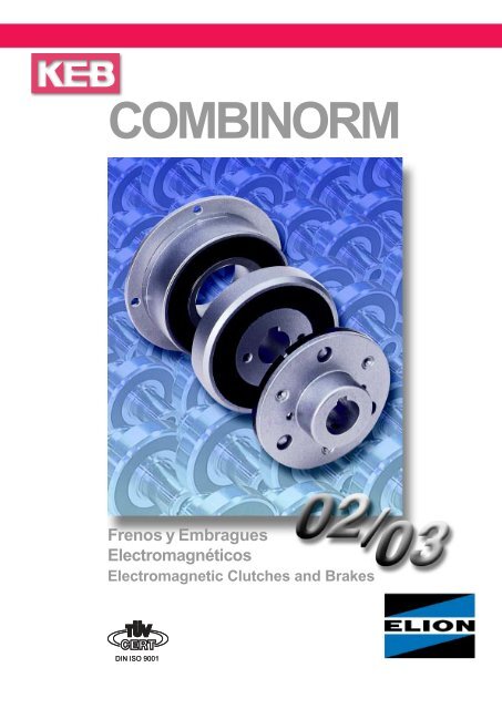
<strong>COMBINORM</strong><strong>Frenos</strong> y EmbraguesElectromagnéticosElectromagnetic Clutches and Brakes
<strong>COMBINORM</strong><strong>COMBINORM</strong> - B ...02.120 <strong>COMBINORM</strong> - C ...03.130GeneralLos KEB <strong>COMBINORM</strong> son frenos y <strong>embragues</strong> actuadoselectro-magnéticamente sin discos de deslizamiento.Este catálogo introduce las diferentes series de <strong>embragues</strong>monodisco y frenos así como <strong>embragues</strong> dentados en susdistintos diseños.Estos productos están fabricados y probados segúnDIN VDE 0580.Tensión de operación 24 V DC, otras tensiones bajo demanda.La tensión DC requerida por KEB <strong>COMBINORM</strong> puede sersuministrada por diferentes rectificadores, trafo-rectificadores asícomo conmutadores electrónicos de las series KEBCOMBITRON.GeneralKEB <strong>COMBINORM</strong> are electromagnetic-actuated clutchesand brakes without sliprings.This catalog introduces finely differentiated series of single-faceclutches and brakes and tooth clutches in varyingdesigns.The products are manufactured and testet according toDIN VDE 0580.Operation voltage 24 V DC, other voltages upon request.The DC voltage required by KEB <strong>COMBINORM</strong> can be suppliedby different rectifiers, trafo-rectifiers as well as electronicswitches of the KEB COMBITRON series.Característicasrevestimientos de fricción libres de asbestos,resistentes al desgaste y estables a la temperaturatiempo de operación ilimitadoaislamiento Clase B, Opción FAprobado CSAsin “backlask“facilidad de implantaciónoperación con bajo ruidotiempos de conmutación cortosmarcado según la directiva de baja tensiónsin par residualAutorizado por el control de calidad (Ü-marca) de lacomisión de prevención. (Opción)montaje simpleConstruction Featuresasbestos-free, wear-resistant and temperature-stablefriction liningsunlimited operating timeInsulation class B, option FCSA approvedbacklash freesafe layoutlow operating noiseshort switching timesmarking according to the low voltage directiveno residual torqueGeneral supervisory board permission and quality control(Ü-marking) by the VdS prevention board. (option)Simple mounting3
<strong>Frenos</strong> con bridaTodas las dimensiones en mmChavetero estándar DIN 6885/1 - P9KK 1Flange mounted brakesAll dimensions in mmStandard keyway DIN 6885/1 - P9ØF4x90°~400ØC2ØA h8ØBNØCH8RØGOØJPXØHR 1SO 1ØEØDØdMR 1SV 1Z 1ØdØC1B 2...02.110 ...02.120 ...02.130Tamaño M 2NP 20°C A h8B C H8 C 1C 2d D E F G H J KSize [Nm] [W] max01 0,5 6 39 33,5 11 13,5 - 6 28 19,5 3,4 2 x 2,1 5,3 4,5 -02 0,75 6 45 38 13 16 13,6 8 32 23 3,4 3 x 2,6 6 5 303 1,5 8 54 47 19 22 20 10 40 30 3,4 3 x 3,1 6 5,5 305 3 10 65 58 26 24 27 15 50 38 3,4 3 x 3,1 6,5 5,5 3,206 7 12 80 72 35 32 36 20 63 50 4,5 3 x 4,1 10 8 3,507 15 16 100 90 42 38 43,5 22 80 60 5,5 3 x 4,1 11 8 4,2508 30 21 125 112 52 48 53,8 30 100 76 6,6 3 x 5,1 11,5 10 509 65 28 150 137 62 58 63,8 35 125 95 6,6 3 x 6,1 15 11,5 5,510 130 38 190 175 80 73 82,1 45 160 120 9 3 x 8,1 21 14,5 611 250 50 230 215 100 92 102,1 60 200 158 9 3 x 10,1 25 17,5 712 500 65 290 270 125 112 127,4 70 250 210 11 4 x 12,1 28 20,5 813 Dimensiones y datos técnicos en dibujo 02.004-4-0100Dimensions and technical datas see drawing 02.004-4-0100TamañoPeso/WeightSize K 1M N O O 1P R R 1S V 1X Z 1[kg]110 120/13001 - 9,3 13,7 5 1,5 1 2,3 4,3 7 2,5 0,1 1 x M 3 0,05 0,0502 1,1 12,1 17 7,5 2 1,3 2,1 4,1 10 4 0,15 1 x M 3 0,1 0,103 1,1 14,7 20 7 2 1,5 2,7 5,3 12 5 0,15 1 x M 4 0,15 0,1505 1,3 15 22 7,5 2 1,5 3 6 12 5 0,2 1 x M 5 0,2 0,2506 1,6 18,8 18 6 3 2 3,8 7,3 15 6 0,2 1 x M 6 0,3 0,307 1,85 24,3 20 7 3 2 4,3 8,3 20 8 0,2 1 x M 6 0,5 0,608 2,15 31 22 8 4 2,5 6 11 25 10 0,2 1 x M 8 0,9 1,109 2,15 36,9 24 9 4 3 6,9 12,9 30 12 0,3 2 x M10 1,7 210 2,65 46,9 26 11 5 4 8,9 15,9 38 15 0,3 2 x M10 3,2 411 3,15 59,2 30 12 5 4,5 11,2 20,2 48 19 0,4 2 x M12 5,9 712 4,15 68 35 15 6 5 13 24 55 22 0,4 2 x M12 11,2 13,513 Dimensiones y datos técnicos en dibujo 02.004-4-0100Dimensions and technical datas see drawing 02.004-4-01006
<strong>COMBINORM</strong> - KCombinación embrague-frenoTodas las dimensiones en mmChavetero estándar DIN 6885/1 - P9KK 1K 1KClutch-brake-combinationAll dimensions in mmStandard keyway DIN 6885/1 - P9L 5ØF4x90°ØC2NN 1ØC2ØA h8ØBØC H8ØdK 2SS 6Ød1ØCH8ØBØAh8~400O 1OR 2XO 1OB 4 ...04.170Tamaño M 2NP 20°C A h8B C H8 C 2d d 1F K K 1K 2L 5N N 1O O 1R 2S S 6X PesoSize [Nm] [W] max. max. WeightEmbr. FrenoClutch Brake[kg]06 7 15 12 80 72 35 36 20 20 4,5 3,5 1,6 11,2 55,1 18 24 6 3 12,9 15 20 0,2 0,8507 15 20 16 100 90 42 43,5 22 25 5,5 4,25 1,85 9,3 61,3 20 26,5 7 3 14,6 20 22 0,2 1,508 30 28 21 125 112 52 53,8 30 30 6,6 5 2,15 8,9 71 22 30 8 4 18,8 25 24,5 0,2 2,709 65 35 28 150 137 62 63,8 35 35 6,6 5,5 2,15 7,9 79,6 24 33,5 9 4 21,8 30 27,5 0,3 4,810 130 50 38 190 175 80 82,1 45 50 9 6 2,65 5 90,8 26 37,5 11 5 27 38 31 0,3 9,511 250 68 50 230 215 100 102,1 60 65 9 7 3,15 3,4 108,2 30 44 12 5 33,8 48 37 0,4 17,912 500 85 65 290 270 125 127,4 70 80 11 8 4,15 5,1 125,6 35 51 15 6 39,2 55 43,5 0,4 31,5Datos necesarios para pedidoKEB <strong>COMBINORM</strong> - K/CRequired order specificationsKEB <strong>COMBINORM</strong> - K/CPar nominal:...... NmNominal torque:..... NmDiseño: brida- o ejeDesign: flange or shaft mountedTensión nominal:..... V DCNominal voltage:...... V DCDiseño de armadura: ..10 / ..30Diámetro del eje en la corona de la armadura Ø:...... mm con o sin chaveteroArmature design: ..10 / ..30Hub bore of the armature Ø:...... mm with keyway or without keywayDiámetro eje del rotor Ø: .. mm con o sin chaveteroRotor bore Ø:...... mm with keyway or without keyway8
<strong>COMBINORM</strong>- CEmbragues con bridaTodas las dimensiones en mmChavetero estándar DIN 6885/1 - P9KK 1RFlange mounted clutchesAll dimensions in mmStandard keyway DIN 6885/1 - P9ØF4x90°ØC2N 1R 1MØAh8ØBØCH8S 1Ød1ØCØEØGØHØDØTSØdØC1ØJV 1Z 1P~400O 1OXB 5 ...03.110 ...03.130Diámetros d, d 1, ≤ 9 mm Tolerancia H8; ≥10 mm Tolerancia H7bores d, d 1, ≤ 9 mm tolerance H8; ≥10 mm tolerance H7Tamaño M 2NP 20°C A h8B C H8 C 1C 2d d 1D E F G H J KSize [Nm] [W] max max01 0,5 6 39 33,5 11 13,5 - 6 6 28 19,5 3,4 2 x 2,1 5,3 4,5 -02 0,75 6 45 38 13 16 13,6 8 8 32 23 3,4 3 x 2,6 6 5 303 1,5 8 54 47 19 22 20 10 10 40 30 3,4 3 x 3,1 6 5,5 305 3 10 65 58 26 24 27 15 15 50 38 3,4 3 x 3,1 6,5 5,5 3,206 7 15 80 72 35 32 36 18 20 63 50 4,5 3 x 4,1 10 8 3,507 15 20 100 90 42 38 43,5 22 25 80 60 5,5 3 x 4,1 11 8 4,2508 30 28 125 112 52 48 53,8 30 30 100 76 6,6 3 x 5,1 11,5 10 509 65 35 150 137 62 58 63,8 35 35 125 95 6,6 3 x 6,1 15 11,5 5,510 130 50 190 175 80 73 82,1 45 50 160 120 9 3 x 8,1 21 14,5 611 250 68 230 215 100 92 102,1 60 65 200 158 9 3 x 10,1 25 17,5 712 500 85 290 270 125 112 127,4 70 80 250 210 11 4 x 12,1 28 20,5 8TamañoPeso/WeightSize K 1M N 1O O 1P R R 1S S 1T V 1X Z 1[kg]110 13001 - 9,3 18 5 1,5 1 2,3 4,3 7 16,5 31 2,5 0,1 1 x M 3 0,1 0,102 1,1 12,1 22,2 7,5 2 1,3 2,1 4,1 10 20,2 34 4 0,15 1 x M 3 0,1 0,103 1,1 14,7 25,4 7 2 1,5 2,7 5,3 12 23,4 43 5 0,15 1 x M 4 0,2 0,205 1,3 15 28,1 7,5 2 1,5 3 6 12 26,1 54 5 0,2 1 x M 5 0,35 0,406 1,6 18,8 24 6 3 2 3,8 7,3 15 22 67 6 0,2 1 x M 6 0,5 0,507 1,85 24,3 26,5 7 3 2 4,3 8,3 20 24 85 8 0,2 1 x M 6 0,9 108 2,15 31 30 8 4 2,5 6 11 25 27 106 10 0,2 1 x M 8 1,6 1,809 2,15 36,9 33,5 9 4 3 6,9 12,9 30 30 133 12 0,3 2 x M10 2,8 3,110 2,65 46,9 37,5 11 5 4 8,9 15,9 38 34 169 15 0,3 2 x M10 5,6 6,311 3,15 59,2 44 12 5 4,5 11,2 20,2 48 40 212,5 19 0,4 2 x M12 9,7 1112 4,15 68 51 15 6 5 13 24 55 47 266 22 0,4 2 x M12 17,9 20,39
Embragues con ejeTodas las dimensiones en mmChavetero estándar DIN 6885/1 - P9Shaft mounted clutchesAll dimensions in mmStandard keyway DIN 6885/1 - P9P 4RF 1QB1Z2x120°ØUP 2S 2N 2ØJ Ød2ØGØCØHØEØDØTMR 1SØdØC1V 1Z 1R 1M 1S 5Ød6ØC4 h7PL 4~400O 5XB 6Diámetros d, d 2≤ 9 mm Tolerancia H8; ≥10 mm Tolerancia H7velocidad máxima permitida ver página 17...03.610 ...03.630 ...03.640bores d, d 2≤ 9 mm tolerance H8; ≥10 mm tolerance H7max. permissible speed see page 17Tamaño M 2NP 20°C B 1C C 1C 4d d 2d 6D E F 1G H J L 4M M 1Size [Nm] [W] max max max01 0,5 6 16,8 11 13,5 13 6 6 6 28 19,5 3,1 2 x 2,1 5,3 4,5 4,8 9,3 9,302 0,75 6 20 13 16 14 8 6 6 32 23 3,1 3 x 2,6 6 5 7,8 12,1 12,103 1,5 8 23 19 22 18 10 10 10 40 30 3,1 3 x 3,1 6 5,5 9,1 14,7 14,705 3 10 28 26 24 28 15 17 15 50 38 3,1 3 x 3,1 6,5 5,5 8,8 15 1506 7 15 36 35 32 - 18 20 - 63 50 5,2 3 x 4,1 10 8 - 18,8 -07 15 20 45 42 38 - 22 25 - 80 60 5,2 3 x 4,1 11 8 - 24,3 -TamañoPeso/WeightSize N 2O 5P P 2P 4Q R R 1S S 2S 5T U V 1X Z Z 1[kg]110 13001 17,3 3,6 1 1,5 8 3 2,3 4,3 7 23,5 9,4 31 17 2,5 0,1 M3 M3 0,1 0,102 19,8 5 1,3 1,5 8 3 2,1 4,1 10 26,2 12,25 34 21 4 0,15 M3 M3 0,1 0,103 23 5,1 1,5 1,5 8 3 2,7 5,3 12 30,4 14,85 43 23 5 0,15 M4 M4 0,2 0,205 26,1 7,8 1,5 1,5 8 3 3 6 12 34,1 15,2 54 32 5 0,2 M4 M5 0,35 0,406 24 6 2 2,5 12 7 3,8 7,3 15 33 - 67 41 6 0,2 M4 M6 0,5 0,507 26,5 7 2 2,5 12 7 4,3 8,3 20 38 - 85 50 8 0,2 M6 M6 0,9 110
<strong>COMBINORM</strong>- CEmbragues con ejeTodas las dimensiones en mmChavetero estándar DIN 6885/1 - P9Tamaño 08... 12size 08... 12Tamaño 06 + 07size 06 + 07A1B1W1TP 4VF 1 2 x 180°WE 1ØC1ØdP 3...03.730 ...03.710Z 1SS 3MØH3R 1 ØGRV 1ØDØEØCØJShaft mounted clutchesAll dimensions in mmStandard keyway DIN 6885/1 - P9Ød3ØD2ØBØAh8~400ØF4x90°PX3O 2 P 5B 7...03.230 ...03.210Tamaño M 2NP 20A h8A 1B B 1C C 1d d 3D D 2E E 1F F 1G H JSize [Nm] [W] max max06 7 15 80 - 72 - 35 32 18 17 63 - 50 - 4,5 - 3 x 4,1 10 807 15 20 100 - 90 - 42 38 22 22 80 - 60 - 5,5 - 3 x 4,1 11 808 30 28 - 62,5 - 56 52 48 30 30 100 85 76 45,75 - 6,5 3 x 5,1 11,5 1009 65 35 - 75 - 68,5 62 58 35 35 125 95 95 55 - 6,5 3 x 6,1 15 11,510 130 50 - 95 - 87,5 80 73 45 50 160 126 120 72,5 - 9 3 x 8,1 21 14,511 250 68 - 115 - 107,5 100 92 60 50 200 126 158 88 - 9 3 x 10,1 25 17,512 500 85 - 145 - 135 125 112 70 60 250 160 210 110 - 11 4 x 12,1 28 20,5Tamaño M O 2P P 3P 4P 5R R 1S S 3T V V 1W W 1X Z 1Peso/WeightSize 210 [kg] 230710 73006 18,8 19 2 - - 4 3,8 7,3 15 41 67 - 6 - - 0,2 1xM6 0,8 0,907 24,3 21,5 2 - - 4,5 4,3 8,3 20 45 85 - 8 - - 0,2 1xM6 1,5 1,608 31 24 2,5 16,2 12 5,5 6 11 25 51,5 106 M5 10 M4 46,5 0,2 1xM8 2,3 2,509 36,9 25 3 18,7 14 5,5 6,9 12,9 30 55 133 M8 12 M5 55 0,3 2xM10 3,7 4,110 46,9 31,5 4 21,5 14 7 8,9 15,9 38 65 169 M8 15 M5 72,5 0,3 2xM10 7 7,711 59,15 32,5 4,5 32,5 20 7 11,15 20,15 48 71 212,5 M10 19 M6 88 0,4 2xM12 13,1 14,312 68 41 5 41 22 8 13 24 55 85 266 M10 22 M8 110 0,4 2xM12 23 2511
L 1Embragues con ejeShaft mounted clutches1)Par de apriete para W 21)Tightening torque for W 2Todas las dimensiones en mmAll dimensions in mmChavetero estándar DIN 6885/1 - P9Standard keyway DIN 6885/1 - P9TL 2P 4 LVF 1 2 x 180°3P 3size 08... 12S 3WTamaño 08... 12Tamaño 06 + 07size 06 + 07K 3ØFXPO 1O 2 P 5S 3B 8...03.810Tamaño M 2NP 20°C 1)M AA h8A 1B B 1C 5D D 2D 3D 4d 4d 7d ESize [Nm] [W] [Nm] max max06 7 15 10 80 - 72 - 30 63 - 25 29 19 17 16 5007 15 20 25 100 - 90 - 40 80 - 35 40 26 25 22 6008 30 28 25 - 62,5 - 56 45 100 85 40 46 30 28,5 25 7609 65 35 50 - 75 - 68,5 60 125 95 50 57 38 33 35 9510 130 50 140 - 95 - 87,5 85 160 126 70 76 55 41 50 12011 250 68 220 - 115 - 107,5 100 200 126 70 76 65 48 50 15812 500 85 500 - 145 - 135 125 250 160 80 89 85 52 60 210Tamaño E 1E 2F F 1G H J J 3K 3L L 1L 2L 3M 2M 3M 4Size06 - 44 4x4,5 - 3x4,1 10 8 2 2,1 32,9 25,6 80 117 30 24 1907 - 68 4x4,5 - 3x4,1 11 8 4 2,8 37,7 29,9 90 129 30 24 2008 45,75 80 - 6,5 3x5,1 11,5 10 4 3,15 35,2 32,15 96 141 35 28 2309 55 100 - 6,5 3x6,1 15 11,5 4 3,2 37,6 34,6 103 160 45 32 3110 72,5 140 - 9 3x8,1 21 14,5 6 4 47,8 43,1 126 200 60 46 4011 88 165 - 9 3x10,1 25 17,5 8 4 47,5 43,3 134 217 65 58 4012 110 215 - 11 4x12,1 28 20,5 8 4 59,6 55,3 162 260 80 70 49Tamaño O 1O 2P P 3P 4P 5S 3T T 1V W W 1W 2X Z Peso/Weight [kg]Size 810 84006 3 19 2 - - 4 41 67 56 - - - 2 x M 6 0,2 M 5 1 1,707 3 21,5 2 - - 4,5 45 85 85 - - - 2 x M 8 0,2 M 6 1,8 308 - 24 2,5 16,2 12 5,5 51,5 106 100 M 5 M 4 46,5 3 x M 8 0,2 M 8 2,7 4,109 - 25 3 18,7 14 5,5 55 133 120 M 8 M 5 55 3 x M10 0,3 M 10 4,2 7,410 - 31,5 4 21,5 14 7 65 169 170 M 8 M 5 72,5 3 x M14 0,3 M 10 8,3 14,611 - 32,5 4,5 23 20 7 71 212,5 200 M10 M 6 88 3 x M16 0,4 M 12 14,5 24,412 - 41 5 27 22 8 85 266 260 M10 M 8 110 3 x M20 0,4 M 12 26 45,2A1B1~400W1E 1ØDØEØD4ØD3 j6ØdØHØJ ØGØd7ØD2ØBØAh812
<strong>COMBINORM</strong>- CEmbragues con ejeTodas las dimensiones en mmChavetero estándar DIN 6885/1 - P9TShaft mounted clutchesAll dimensions in mmStandard keyway DIN 6885/1 - P9L 3M 2W 2 M 4 J 3Tamaño 08... 12size 08... 12Tamaño 06 + 07size 06 + 07ØT1ØE2ØC5Ød4Ød7S 3Ød~400W 2Z2x120°M 3B 9Instrucciones de Montaje...03.840Mounting InstructionsPara los <strong>embragues</strong> con acoplamiento elástico (Tipo...03.840) deben aplicarse las siguientes instrucciones:Los tornillos radial y axial que conectan el elemento de gomacon la corona, deben apretarse con el par (M A) indicado en latabla, utilizando una llave dinamométrica.Asegúrese que cuando apriete los tornillos el casquillo dealuminio no se enrosca en la parte de goma y queda bienalineado. Para reducir la fricción entre la cabeza del tornillo y elbuje de aluminio, untar con una pequeña cantidad de grasa lacabeza del tornillo antes de insertarlo. Si fuese necesario usela herramienta apropiada para sujetar el elemento de gomaimpidiendo que sea retorcido mientras aprieta los tornillos.Esto es particularmente importante en los tornillos radiales, deotro modo las caras curvadas entre el buje de aluminio y lacorona no contactarán en se área total, sólo en dos lados. Estoconducirá inevitablemente a que se aflojen los tornillos y a ladestrucción del embrague. Si el embrague es suministradopre-ensamblado, no lo desmonte, instálelo directamente.For flexible clutches (Type ...03.840) the following additionalinstructions are applicable:The radial and axial screws connecting the rubber elementto the hubs must all be tightened to the torque (M A) given inthe table, using a torque wrench.Ensure that when tightening the screws the aluminiumbushes do not twist in the rubber part and that they sitsquarely. In order to reduce friction between the screw headand the aluminium bush smear a small amount of greaseunder the head of the screw before fitting. If necessary use asuitable tool to apply counter pressure on the element toprevent twisting of the rubber part while tightening thescrews. This is particularly important with the radial screwsotherwise the curved faces between the aluminium bush andthe hub will not engage on the full area but only across thetwo sides. This will inevitably lead to slackening of thescrews and destruction of the clutch. If the clutch is suppliedin a pre-assembled state, do not dismantle it, but fit it in thiscondition.Tamaño Tolerancia [mm] de los acoplamientos elásticosradialaxial06 1,5 207 1,5 308 1,5 309 2 410 2 511 2 512 2 5Size Compliance [mm] of flexible clutchesradialaxial06 1,5 207 1,5 308 1,5 309 2 410 2 511 2 512 2 513
Embragues dentados con bridaTodas las dimensiones en mmChavetero estándar DIN 6885/1 - P9KK 1Flange mounted tooth clutchesAll dimensions in mmStandard keyway DIN 6885/1 - P9R 3FØC2N 1R 4M 5ØAh8ØBØCH8S 1Ød1ØEØDØT1SØdØGØH1ØC1ØJV 1Z 1P~400O 1OXB 10...07.110 ...07.130Tamaño M 2NP 20°C A h8A 1B B 1C H8 C 1C 2D d 1D 2d 3d E E 1Size [Nm] [W] max max max06 21 15 80 - 72 - 35 32 36 63 20 - 17 18 50 -07 45 20 100 - 90 - 42 38 43,5 80 25 - 22 22 60 -08 90 28 125 62,5 112 56 52 48 53,8 100 30 85 30 30 76 45,7509 195 35 150 75 137 68,5 62 58 63,8 125 35 95 35 35 95 5510 390 50 190 95 175 87,5 80 73 82,1 160 50 126 50 45 120 72,5Tamaño F F 1G H 1J K K 1M 5N 1O O 1O 2P P 3P 4P 5Size06 4x4,5 - 3x4,1 8 8 3,5 1,6 20,3 24 6 3 19 2 - - 407 4x5,5 - 3x4,1 8 8 4,25 1,85 26,4 26,5 7 3 21,5 2 - - 4,508 4x6,6 6,5 3x5,1 11,2 10 5 2,15 33,6 30 8 4 24 2,5 16,2 12 5,509 4x6,6 6,5 3x6,1 15 11,5 5,5 2,15 41,2 33,5 9 4 25 3 18,7 14 5,510 4x9 9 3x8,1 16 14,5 6 2,65 50,8 37,5 11 5 31,5 4 21,5 14 7Tamaño R 3R 4S S 1S 3T 1V V 1W W 1X 1Z 1Peso/Weight [kg]Size 210/710 230/730 110 13006 5,3 8,8 15 22 41 68 - 6 - - 0,15 1 x M 6 1 1 0,7 0,707 6,4 10,4 20 24 45 86,5 - 8 - - 0,2 1 x M 6 1,7 1,8 1,1 1,208 8,6 13,6 25 27 51,5 108 M5 10 M 4 46,5 0,2 1 x M 8 2,6 2,8 1,9 2,109 11,2 17,2 30 30 55 135 M8 12 M 5 55 0,2 2 x M10 4,1 4,4 3,2 3,510 12,8 19,8 38 34 65 172,2 M8 15 M 5 72,5 0,25 2 x M10 7,5 8,3 6,1 6,914
<strong>COMBINORM</strong>- TEmbragues dentados con ejeTodas las dimensiones en mmChavetero estándar DIN 6885/1 - P9A1Tamaño 08... 10size 08... 10Tamaño 06 + 07size 06 + 07B1W1T1P 4VF 1 2 x 180°WE 1ØC1Ød...07.730M 5R 4S...07.7103R 3S 3P 3ØH 1ØGØDØEØCShaft mounted tooth clutchesAll dimensions in mmStandard keyway DIN 6885/1 - P9Ød3ØD2ØBØAh8Z 1V 1ØJ~400ØFPXO 1O 2 P 5B 11Embragues dentadosPrincipio de funcionamientoLos KEB <strong>COMBINORM</strong> - T son <strong>embragues</strong> dentadosoperados electro-magnéticamente para trabajo en seco oen baño de aceite. El par es transmitido sin juego radialmediante los dientes frontales templados. Transmitengrandes pares con menor requerimiento de espacio....07.230 ...07.210Tooth clutchesOperating principleKEB <strong>COMBINORM</strong> - T are electromagnetically operatedtooth clutches for wet or dry operation. Torque is transmittedby the leading faces of hardened Hirth-type serrationsand is backlash free. Large torques are transmitted withless space requirement.Instrucciones de MontajeEn los KEB <strong>COMBINORM</strong> - T son aplicables las siguientesinstrucciones así como las indicadas en la página 5:Conmutar sólo en estado parado o en sincronismo.La Armadura y el Rotor están emparejados en fábrica yno pueden intercambiarse.La armadura debe alinearse y centrarse perfectamenteantes de anclarla.Mounting InstructionsFor tooth clutches KEB <strong>COMBINORM</strong> - T the following instructionsand the instructions from page 5 are applicable.Switch-on only during standstill or synchronous operation.Armature and rotor are aligned to each other ex factoryand may not be exchanged.The armature must be accurately aligned at the outerdimension before attachment.15
Tiempos de conmutación y alimentación eléctricaSwitching times and power supplyDiagramas corriente/tiempo y par/tiempoCurrent/time and torque/time diagramsIt 1t 11t 2I NM 2NTiempo de engancheTiempo de reacciónTiempo de liberaciónCorriente nominal de la bobinaPar nominaltTiempos de conmutación medios [ms] con entre-hierronominal.MM2N0,9M2Nt 11t 1 t 2t0,1M2Nt 1t 11t 2I NM 2NEngaging timeEngaging delay timeRelease timeRated magnet currentNominal torqueAverage switching times [ms] with nominal air gap.B 12Una sobre-excitación de corto tiempo produce menores tiemposde conmutación y mayor precisión.t 1Tiempo de enganche [ms]Tiempo desde que se conecta la corriente hastaque el par nominal es alcanzado.t 11Tiempo de reacción [ms]Tiempo desde que se conecta la corriente hastaque el par aumenta.t 2Tiempo de liberación [ms]Tiempo desde que se desconecta la corrientehasta 0,1 M 2N.Short time over excitation results into short switching times andhigh switching accuracy.t 1Engaging time [ms]Time from connecting the current until therated torque is attained.t 11Engaging delay time [ms]Time from connecting the current until thetorque rises.t 2Release time [ms]Time from disconnecting the current until 0,1 M 2N.Tamaño / size 01 02 03 05 06 07 08 09 10 11 12t 11[ms]tensión nominal 4 5 7 10 14 18 23 25 29 37 55t 1[ms]nominal voltage 10 14 17 32 48 74 81 90 161 201 295t 11[ms]3 x tensión nominal 2 2 3 5 6 8 10 12 14 16 25t 1[ms]3 x nominal voltage 5 6 7 16 22 33 37 42 69 91 125t 2[ms] DC 5 6 7 10 14 19 40 68 100 130 200t 2[ms] AC 17 19 22 30 39 61 115 220 400 650 900t 11[ms]tensión nominal 2 3 3 5 6 8 10 13 15 23 35t 1[ms]nominal voltage 5 8 8 17 24 38 42 48 85 118 155t 11[ms]3 x tensión nominal 1 2 2 3 3 4 5 6 8 10 16t 1[ms]3 x nominal voltage 3 4 4 8 11 17 20 22 38 50 76t 2[ms] DC 3 4 5 8 10 15 50 85 100 140 200t 2[ms] AC 17 20 25 40 70 95 240 300 400 600 800Tiempos de conmutación / switching timesEmbragues / clutches<strong>Frenos</strong> / brakes16
<strong>COMBINORM</strong>Datos TécnicosTechnical DataTamaño / size 01 02 03 05 06 07 08 09 10 11 12JMomentos de inerciamoments of inertiaFricción, desgasteswitching work, wearRotor / rotorsFigura B4, B5, B7, B10 0,025 0,035 0,15 0,375 0,825 2,38 7,25 21,9 67,4 200 450picture B7, B11 0,027 0,038 0,17 0,40 0,9 2,6 8,0 24,0 73,0 220 500B 8, B10 1,02 3,05 8,76 26,0 82,5 230 520Armadura / armaturesFigura B2, B5, B6, B7, B8, B9, B10, B11 a) 0,010 0,014 0,045 0,122 0,366 1,07 3,72 10,6 40,0 115 311picture B2, B5, B6, B7, B10, B11 b) 0,013 0,021 0,068 0,18 0,53 1,57 5,29 15,1 50,1 159 437B3 b) 0,82 2,6 10,3 27,0 101B4 b) 0,99 2,7 9,12 25,4 88,9 272 814Corona / hub 0,16 0,49 0,89 3,77 19,9 41,2 118Anillo intermedio / intermediate ring Figura / picture B9 1,5 5,0 11,0 30,0 112 253 814Elemento de goma/ rubber element 0,35 1,25 3,3 7,0 50,2 102 450W Rmax0,04 0,05 0,08 0,12 0,19 0,31 0,48 0,75 1,25 2,0 2,9W R0,10,23 0,30 0,43 0,63 0,95 1,63 2,53 4,09 6,66 10,4 16,3P R maxEmbrague / clutch 20,3 28,6 40,6 58,3 80,6 114 161 228 322 458 647P R maxFreno / brake 12,8 18,6 26,9 38,9 58,3 79,2 114 164 236 339 489X n0,3 0,45 0,45 0,6 0,7 0,7 0,7 0,9 1,0 1,2 1,2X 0,1 0,15 0,15 0,2 0,2 0,2 0,2 0,3 0,3 0,4 0,4n max10000 10000 10000 10000 8000 6000 5000 4000 3000 3000 2000Excepción / exception tipo ...03.610/630/640 1500 1500 1500 1500 1500 1500a) sin corona b) con coronaa) without hub b) with hubLeyendaM 2Npar nominal estático [Nm]M erfpar requerido [Nm]M Lpar resistente [Nm]M apar de frenado dinámico [Nm]J momento de inercia [10 -4 kgm 2 ]P potencia del accionamiento [kW]n velocidad [min -1 ]n maxvelocidad máxima [min -1 ]K factor de seguridad (K≥2) [-]X entre-hierro nominal [mm]X nentre-hierro, al cual se recomienda [mm]un nuevo reajusteW Rfricción [J]W Rmaxfricción permitida por operación [10 4 J]W R0,1fricción hasta desgastar 0,1 mm [10 7 J]P Rmaxfricción permitida por segundo [J/s]Los frenos y <strong>embragues</strong> monodisco, alcanzan sin dificultad, lospares indicados en la tabla después de un proceso de rodaje de100 rpm. En condiciones diferentes o con velocidades de rotaciónsustancialmente mayores el par puede en ciertas circunstanciasser menor.LegendM 2Nstatic rated torque [Nm]M erfrequired torque [Nm]M Lload torque [Nm]M adynamic braking torque [Nm]J moment of inertia [10 -4 kgm 2 ]P driving power [kW]n speed [min -1 ]n maxmaximum speed [min -1 ]K safety factor (K≥2) [-]X rated air gap [mm]X nclearance at which an adjustment [mm]is recommendedW Rfriction [J]W Rmaxpermissible friction per switching operation [10 4 J]W R0,1friction work up to 0,1 mm wear [10 7 J]P Rmaxpermissible friction work per second [J/s]Single-face clutches and brakes obtain the torques listed in thetable without difficulty after a run-in phase of 100 rpm. In thenew state or in case of substantially higher speed the torquemay under certain circumstances be smaller.17
DimensionadoDecisivo para el dimensionado de los KEB <strong>COMBINORM</strong> son: elpar requerido, la carga térmica, el tiempo de frenado y la vida útil.DimensioningDecisive for the dimensioning of the KEB <strong>COMBINORM</strong> are therequired torque, thermal load, braking time and service life.Par Nominal M 2NPara asegurar que KEB <strong>COMBINORM</strong> trabaja correctamenteincluso bajo condiciones extremas, el par requerido debemultiplicarse por un factor de seguridad. La selección del factor deseguridad depende esencialmente de la aplicación.Rated Torque M 2NTo ensure that KEB <strong>COMBINORM</strong> safely works even under extremeconditions, the required torque must be multiplied by asafety factor. The selection of the safety factor depends essentiallyon the application.M 2N = M erf · K K ≥ 2 M erf =erforderliches par requerido [Nm] Moment [Nm]required torque [Nm]El par dinámico de un freno monodisco puede sersustancialmente menor que el par nominal.The dynamic torque of a single-disc brake may be substantiallylower than the rated torque.Par Requerido M erfRequired Torque M erfMuy a menudo el par requerido es una mezcladel par dinámico y del estático.¡Observe el signo!M erf= M A± M LM A= J · αThe required torque very often is a mixture ofdynamic and static load.Observe sign!Definición aproximada del par requeridoRough Definition of the required TorqueSi el momento de inercia es desconocido y lapotencia del accionamiento ha sido fijada, elpar requerido se calculará como sigue:M erf= 9550 ·PnIf the mass moment of inertia is unknown andthe driving power is fixed then the requiredtorque is calculated as follows:Carga TérmicaThermal LoadEl dimensionado según el parrequerido es posible sólo en algunoscasos.Al decelerar la carga y el momento deinercia son reducidos en el eje, laenergía cinética es convertida encalor (trabajo de fricción). El trabajo de fricción permitido no debeser superado.Los valores para W Rmaxy W R0,1han sido determinados mediantepruebas. La velocidad, el momento de inercia y la frecuencia deconmutación han sido cuidadosamente seleccionados paraobtener la temperatura de operación máxima permitida.Dependiendo de la aplicación estos valores pueden sersuperados.J · n 2 M 2NW R= ·182,5 M 2N± M LW R≤ W RmaxThe dimensioning solely on the basisof the required torque is permissibleonly in very few cases.When decelerating or acceleratingthe load and the mass moment of inertiareduced to the shaft, the kineticenergy is converted into heat (friction work). The permissiblefriction work may not be exceeded.The values for W Rmaxand W R0,1have been determined by tests.Speed, mass moment of inertia and switching frequency havebeen carefully selected to obtain the maximum permissible operatingtemperature. Dependent on the actual application thesevalues may be exceeded.Tiempo de deslizamiento t 3[ms]El tiempo desde que el para empieza aincrementar hasta que se alcanza el parde sincronización.Slip time t 3[ms]J · ∆nt 3= 104,6 · + t 11M 2N± M LThe time from the beginning of thetorque rise until attaining the moment ofsynchronization.18
<strong>COMBINORM</strong>Vida útil en conmutaciones hasta el reajusteService life in switching operations until readjustmentCon la variable X nla vida útil hasta el reajuste puede ser calculada.La variable X nes un valor recomendado.Dependiendo de la aplicación, deberevisarse cuando tiene que realizarse elreajuste del entre-hierro.L n=With the variable X nthe service life can be calculated until thereadjustment.The variable X nis a recommendedvalue. According to the application itmust be checked when the readjustmenthas to be made.(X n- X) · W R0,10,1 · W RRotorArmadura / Armaturecon rodamiento with bearingTamaño / Size 12 11 10 09 08 07 06 05 03 02 01 01 02 03 05 06 07 08 09 10 11 12 12 11 10 09 08 07 06 05 03 02 01Diámetro mínimo (sin chavetero) Diámetro mínimo (sin chavetero) Diámetro mínimo (sin chavetero)Minimum bore (without keyway) Minimum bore (without keyway) Minimum bore (without keyway)d a P9 b c29 24 16 14 11 9 7 6 - - - - - - - 7 9 11 14 16 24 29 29 24 16 14 11 9 7 7 - - -5 56 7 6 6 6 67 H8 2 88 9 8 8 8 8 8 8910,4310 11,4 10 10 10 10 10 10 10 101112,8412 13,8 12 12 12 12 12 1214 16,3 15,2 14 14 1415 5 17,3 16,2 15 15 15 15 15 15 15 15 1517 19,3 18,2 17 17 17 17 1718 20,8 19,61921,8 20,6 19 19620 22,8 21,6 20 20 20 20 20 20 20 20 2022 24,8 23,624 27,3 26,0 2425 8 28,3 27,0 25 25 25 25 25 25 25 2528 31,3 30,0 28 2830 33,3 32,0 30 30 30 30 30 30 30 30 3032 35,3 34,435 H7 10 38,3 37,4 35 35 35 35 35 35 35 3538 41,3 40,4 384043,3 42,2 40 40 40 40 40 401242 45,3 44,2a P9d Diámetro / Bore45 48,8 47,1 45 45 Chavetero DIN 6885 45 45 45 45a P948 14 51,8 50,1Keyway width50 53,8 52,1 50 50 50 Chavetero std DIN6885/1b50 50 50 50 50Depth over standard keyway55 16 59,3 57,4 55 55 55 5560 18 64,4 62,3 60 60 cChav. reducido DIN 6885/3Depth over reduced keyway60 60 6065 69,4 67,3 65 65 65diámetros disponibles “d“ con chav. DIN 6885/17074,9 72,7 70 7020available bores “d” with standard keyway75 79,9 77,7diámetros dispo. “d“ con chavetero DIN 6885/38085,4 83,1 80available bores “d” with reduced keyways2285 90,4 88,190 25 95,4 92,9Diámetros preferentes / Preferred bore sizesdb / c19
ELION, S.A.U.Farell, 508014 BarcelonaTel. 932 982 000http://www.elion.es© KEB 00.00.000-4100 06/2003 - Traducido al castellano por Francesc Puig Font - Enero 2007