assembly instructions - Media.hobbypeople.net - Global Hobby ...
assembly instructions - Media.hobbypeople.net - Global Hobby ...
assembly instructions - Media.hobbypeople.net - Global Hobby ...

Create successful ePaper yourself
Turn your PDF publications into a flip-book with our unique Google optimized e-Paper software.
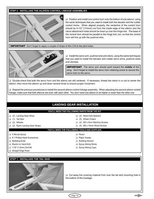
Step 2: installing the aileron control linkage assemblies❑ Position and install one control horn onto the bottom of one aileron, usingthe same techniques that you used to install both the elevator and the ruddercontrol horns. When aligned properly, the centerline of the control hornshould be 4-1/2" (114mm) out from the inside edge of the aileron and theclevis attachment holes should be lined up over the hinge line. The base ofthe control horn should be parallel to the hinge line, too, so that the controlhorn will line up with the pushrod wire.IMPORTANT Don't forget to apply a couple of drops of thin C/A to the pilot holes.❑ Install the servo arm, pushrod wire and clevis, using the same techniquesthat you used to install the elevator and rudder servo arms, pushrod wiresand clevises.IMPORTANT The servo arm should point toward the middle of thewing. Don't forget to install the servo horn retaining screw to secure theservo horn to the servo.❑ Double-check that both the servo horn and the aileron are still centered. If necessary, thread the clevis in or out to center theaileron, then move the aileron up and down several times to ensure proper movement.q Repeat the previous procedures to install the second aileron control linkage <strong>assembly</strong>. When adjusting the second aileron controllinkage, make sure that both ailerons are even with each other. You don’t want one aileron to be higher or lower than the other one.LANDING GEAR INSTALLATIONYou'll Need the following parts FROM THE KIT:❑ (2) Landing Gear Wiresq (1) Tail Skid❑ (2) Wheels❑ (2) Nylon Landing Gear Strapsq (2) Nylon Axle Spacersq (2) Wheel Collarsq (2) M3 x 5mm Machine Screwsq (4) M2 x 10mm Wood ScrewsYou'll Need the following TOOLS AND SUPPLIES:❑ 5 Minute Epoxyq # 1 Phillips Head Screwdriver❑ Modeling Knifeq Electric or Hand Drillq 1/16" (1.6mm) Drill Bit❑ Straight Edge Ruler❑ Pencilq Paper Towelsq Rubbing Alcoholq Epoxy Mixing Sticksq Epoxy Mixing CupsStep 1: installing the tail skid❑ Cut away the covering material from over the tail skid mounting hole inthe bottom of the fuselage.Page 16