Simulation of Water-Gas Shift Membrane Reactor for Integrated ...
Simulation of Water-Gas Shift Membrane Reactor for Integrated ...
Simulation of Water-Gas Shift Membrane Reactor for Integrated ...
- No tags were found...

You also want an ePaper? Increase the reach of your titles
YUMPU automatically turns print PDFs into web optimized ePapers that Google loves.
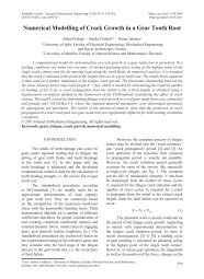
Strojniški vestnik - Journal <strong>of</strong> Mechanical Engineering 57(2011)12, 911-9268 the difference is negative) after which the rate<strong>of</strong> permeation becomes faster than the production<strong>of</strong> H 2 . As seen from Fig. 8, the maximumdifference is reached around the 400 th sectionand the permeation rate becomes almost equal tothe reaction rate around the 4000 th section. Therate <strong>of</strong> reaction rises slightly at the end becauseat that point the concentration <strong>of</strong> H 2 is closeto zero and the effect <strong>of</strong> the backward WGSRalmost disappears. The increase in the reactionrate also causes the rate <strong>of</strong> permeation to increase,because more H 2 is produced, which immediatelypermeates through the membrane because theprocess is not permeation limited.in the retentate stream at the beginning and H 2converted from CO until that point permeatethrough the membrane. From that point on, onlythe H 2 that is converted from CO is permeatingthrough the membrane.Rapid permeation <strong>of</strong> H 2 is responsible <strong>for</strong>molar fractions <strong>of</strong> H 2 O and CO to experiencethe first inflection point around the 400 th section.The fractions reach the second inflection pointaround 2000 th section, where majority <strong>of</strong> H 2 onthe retentate side already permeated through themembrane. From that point on both fractionsgradually reduce towards the end <strong>of</strong> reactor wherethe consumption <strong>of</strong> H 2 O and CO again slightlyincreases on behalf <strong>of</strong> increase in the reaction rate.The molar fraction <strong>of</strong> CO 2 is increasing fastin the first 2000 sections because <strong>of</strong> H 2 permeationand because <strong>of</strong> CO conversion. This can be seenfrom a graph where after 2000 sections the rate <strong>of</strong>CO 2 <strong>for</strong>mation starts to decrease since virtuallyall <strong>of</strong> H 2 that was present in the stream permeatesthrough the membrane. At the end, the rate <strong>of</strong>CO 2 <strong>for</strong>mation slightly increases on behalf <strong>of</strong> theincrease in the reaction rate.Fig. 8. Difference between the rate <strong>of</strong> H 2production and the rate <strong>of</strong> H 2 permeation in eachsection <strong>of</strong> the reactorAs it can be seen from Fig. 9, the molarfraction <strong>of</strong> H 2 actually rises at the beginning eventhough the rate <strong>of</strong> permeation is greater as the rate<strong>of</strong> <strong>for</strong>mation. By constantly extracting H 2 fromthe retentate stream, the joint molar flow alsodecreases. Since at the beginning the differencebetween the permeation and the production rates<strong>of</strong> H 2 is not big enough, the H 2 molar flow inretentate stream is decreasing but not as fast as themolar flows <strong>of</strong> H 2 O and CO. As a consequence,the molar fraction <strong>of</strong> H 2 actually rises slightlyuntil the 64 th section where, on behalf <strong>of</strong> a sharpincrease in the permeation rate, H 2 starts to rapidlypermeate through the membrane.After reaching the peak at the 64 th sectionthe molar fraction <strong>of</strong> H 2 starts to decrease fastuntil the 1000 th section. Around the 2000 th sectionthe permeation already slows down considerablyand around the 4000 th section most <strong>of</strong> H 2 presentFig. 9. Change in molar fractions <strong>of</strong> species andthe CO conversion throughout the reactorBased on the input values, the calculatedmolar composition <strong>of</strong> the retentate stream ispresented in Table 3. Below, these values are alsocompared to the simulation results from AspenPlus.In order to keep the MR operating atisothermal conditions, approximately two thirds<strong>of</strong> all heat, produced from the WGSR, would needto be removed from the reactor in the first 2000sections (see Fig. 10). The cooling tubes should bedistributed in such a way that they would insure920 Lotrič, A. ‒ Sekavčnik, M. ‒ Kunze, C. ‒ Splieth<strong>of</strong>f, H.