MANUAL ON STREAM GAUGING - E-Library - WMO
MANUAL ON STREAM GAUGING - E-Library - WMO
MANUAL ON STREAM GAUGING - E-Library - WMO
- No tags were found...

Create successful ePaper yourself
Turn your PDF publications into a flip-book with our unique Google optimized e-Paper software.
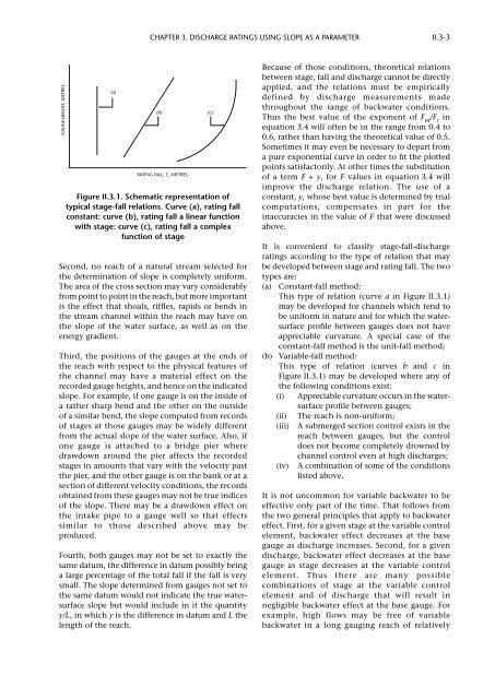
Chapter 3. DISCHARGE RATINGS USING SLOPE AS A PARAMETERII.3-3GAUGE HEIGHT, METRES(a)Second, no reach of a natural stream selected forthe determination of slope is completely uniform.The area of the cross section may vary considerablyfrom point to point in the reach, but more importantis the effect that shoals, riffles, rapids or bends inthe stream channel within the reach may have onthe slope of the water surface, as well as on theenergy gradient.Third, the positions of the gauges at the ends ofthe reach with respect to the physical features ofthe channel may have a material effect on therecorded gauge heights, and hence on the indicatedslope. For example, if one gauge is on the inside ofa rather sharp bend and the other on the outsideof a similar bend, the slope computed from recordsof stages at those gauges may be widely differentfrom the actual slope of the water surface. Also, ifone gauge is attached to a bridge pier wheredrawdown around the pier affects the recordedstages in amounts that vary with the velocity pastthe pier, and the other gauge is on the bank or at asection of different velocity conditions, the recordsobtained from these gauges may not be true indicesof the slope. There may be a drawdown effect onthe intake pipe to a gauge well so that effectssimilar to those described above may beproduced.Fourth, both gauges may not be set to exactly thesame datum, the difference in datum possibly beinga large percentage of the total fall if the fall is verysmall. The slope determined from gauges not set tothe same datum would not indicate the true watersurfaceslope but would include in it the quantityy/L, in which y is the difference in datum and L thelength of the reach.(b)RATING FALL, F r, METRESFigure II.3.1. Schematic representation oftypical stage-fall relations. Curve (a), rating fallconstant: curve (b), rating fall a linear functionwith stage: curve (c), rating fall a complexfunction of stage(c)Because of those conditions, theoretical relationsbetween stage, fall and discharge cannot be directlyapplied, and the relations must be empiricallydefined by discharge measurements madethroughout the range of backwater conditions.Thus the best value of the exponent of F m/F rinequation 3.4 will often be in the range from 0.4 to0.6, rather than having the theoretical value of 0.5.Sometimes it may even be necessary to depart froma pure exponential curve in order to fit the plottedpoints satisfactorily. At other times the substitutionof a term F + y, for F values in equation 3.4 willimprove the discharge relation. The use of aconstant, y, whose best value is determined by trialcomputations, compensates in part for theinaccuracies in the value of F that were discussedabove.It is convenient to classify stage-fall-dischargeratings according to the type of relation that maybe developed between stage and rating fall. The twotypes are:(a) Constant-fall method:This type of relation (curve a in Figure II.3.1)may be developed for channels which tend tobe uniform in nature and for which the watersurfaceprofile between gauges does not haveappreciable curvature. A special case of theconstant-fall method is the unit-fall method;(b) Variable-fall method:This type of relation (curves b and c inFigure II.3.1) may be developed where any ofthe following conditions exist:(i) Appreciable curvature occurs in the watersurfaceprofile between gauges;(ii) The reach is non-uniform;(iii) A submerged section control exists in thereach between gauges, but the controldoes not become completely drowned bychannel control even at high discharges;(iv) A combination of some of the conditionslisted above.It is not uncommon for variable backwater to beeffective only part of the time. That follows fromthe two general principles that apply to backwatereffect. First, for a given stage at the variable controlelement, backwater effect decreases at the basegauge as discharge increases. Second, for a givendischarge, backwater effect decreases at the basegauge as stage decreases at the variable controlelement. Thus there are many possiblecombinations of stage at the variable controlelement and of discharge that will result innegligible backwater effect at the base gauge. Forexample, high flows may be free of variablebackwater in a long gauging reach of relatively