Vaneaxial Fans Axiad II Adjustable Pitch Airfoil (Model ... - Aerovent
Vaneaxial Fans Axiad II Adjustable Pitch Airfoil (Model ... - Aerovent
Vaneaxial Fans Axiad II Adjustable Pitch Airfoil (Model ... - Aerovent

You also want an ePaper? Increase the reach of your titles
YUMPU automatically turns print PDFs into web optimized ePapers that Google loves.
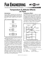
Selection of AXIAD <strong>II</strong> Axial Flow <strong>Fans</strong> Using Simplified Selection Charts<strong>Vaneaxial</strong> fans are usually rated in terms of total pressure (pt), total pressure being the sum of the system static resistance (ps), plusthe velocity pressure (pv) in the duct leaving the fan.In the case of AXIAD <strong>II</strong> fans, the total pressure shown on the individual fan curves is as measured in the annulus of the vanesection, so we have to add the impact loss (pi) to ps and pv to arrive at pt. This is done because the impact loss varies to a considerabledegree with variations in discharge duct geometry.All of this is discussed in detail in our brochure “<strong>Vaneaxial</strong> Fan Characteristics and Application Fundamentals.” That brochurepresents a more accurate method for computing these discharge or impact losses, and this method is used at the factory to checkselections on orders before they are manufactured.However, a simplified method would be more desirable for the use of consultants and sales representatives, and this bulletinpresents such a method. The enclosed data will permit quick selections and performance comparisons between alternate selections.This method will give you the total pressure within 2% of the computed figure arrived at from the formulas in the brochure.Guidelines for Use of Simplified Selection TablesTo select an axial flow fan using the simplified selection charts, it is only necessary to know:1. Airflow (CFM)2. Static pressure (SP)3. Approximate duct velocity downstream of the fanWith this information you can make an initial selection of fan size and then verify, using the attached charts, that the selectionis a good one or that an alternate size should be chosen.If a single fan system is to be selected, it is desirable to pick the operating point at the area of maximum efficiency. Selectionin this part of the curve insures economical operation and good sound characteristics.Since job conditions and calculated requirements do not always agree, it is necessary to allow a safety factor in pressure and flowwhen making the selection so the fan can do more if field conditions so require. For this reason, do not select a fan at more than90% of the rated pressure shown on the curve at design flow, and do not select a fan at higher than the maximum indicated bladeposition.If fans are to be selected to operate in parallel, care must be taken so that fans which come on while the system is operating donot pass through the “dip” in the fan curve, which is the stall region. To prevent this condition, parallel fans should be selected sothat the system curve crosses the maximum blade setting line at a point below the level of the dip. This procedure is necessary toavoid the possibility of the last fan to be started having to pass through the dip in the stall envelope above the performance curve.Since this fan must come up to the system operating pressure before it can contribute to system flow, there is a possibility, if thefan is not selected in this manner, that it may go into a stall condition and not perform as expected.How To Select <strong>Fans</strong>To make a simplified selection, proceed as follows:1. Using the individual fan performance charts (higher static pressures require higher RPM), make a tentative selection of fandiameter and hub size. Remember that total pressure will typically be 1" to 3" higher than the static pressure.2. Using Chart 3 and 4, enter at the bottom with CFM, go up vertically to the tentative fan selection, and then read left to determineV1, the air velocity in the annulus of the fan.3. Determine velocity pressure (pv), and impact loss (pi) from Chart 5 (if you do not intend to use a diffuser) or Chart 6 (if therewill be a diffuser). In either case, enter the chart with the duct velocity downstream of the fan, rise to V1 ascertained in Step 2,and read left for pv + pi.If the fan discharges into a plenum, use the velocity in the cross-sectional area of the plenum as duct velocity.If a sound trap is located in the plenum, use the normal face velocity through the trap as duct velocity.Add pv + pi to your static pressure to arrive at pt. P1 can now be used directly on the individual fan curve to confirm thatthe selection is a good one or that it should be revised.4. If the selection is to the left of the optimum efficiency, you may have too large of a fan, and should try the next smaller diameter.If the selection is well below the point of optimum efficiency, you may have selected too large of a hub size, or perhaps a fanwith fewer blades will prove more efficient. In making alternate selections, retrace Steps 2, 3, and 4 for your new fan size.®45 <strong>Aerovent</strong> Bulletin FA-300