(Model CBDF) - Catalog 360 - Aerovent
(Model CBDF) - Catalog 360 - Aerovent
(Model CBDF) - Catalog 360 - Aerovent
- No tags were found...

You also want an ePaper? Increase the reach of your titles
YUMPU automatically turns print PDFs into web optimized ePapers that Google loves.
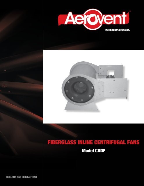
®The Industrial Choice.FIBERGLASS INLINE CENTRIFUGAL FANS<strong>Model</strong> <strong>CBDF</strong>BULLETIN <strong>360</strong> October 1998
Design & Construction<strong>Aerovent</strong>’s Fiberglass <strong>CBDF</strong> Inline Centrifugal Fan is designedto provide straight-through airflow. This combines the compactadvantage of an axial flow fan with the performance characteristicsof a centrifugal fan. Constructed of fiberglass (FRP), the<strong>CBDF</strong> fan is primarily used for exhausting gases, fumes andvapors from chemical processes.Airstream parts are constructed of fiberglass reinforcedplastic for resistance to a wide variety of acids, alkalies, andother chemical agents. Please refer to the “Corrosion ResistanceGuide” on page 3 for a list of the specific chemical agents. Forapplications that require exhausting chemicals that may attackpolyester resin, special resins and reinforcing materials are available,as an option, to withstand these conditions.Advantages of Fiberglass Fans• Superior corrosion resistance to gases, fumes, and vapors• Lower maintenance costs• More economical than stainless steel construction• Lighter weight than steelDesign Features• Wheel Design — <strong>Aerovent</strong>’s <strong>CBDF</strong> fiberglass “FA” wheeldesign features a backward inclined airfoil blade. This wheeldesign offers a power limiting characteristic with the addedadvantage of high operating efficiency and low noise levels.• Corrosion Resistance — All airstream parts are de-signedwith fiberglass reinforced plastic and are resistant to mostchemicals. Please refer to the “Corrosion Resistance Guide”on page 3 for a list of the specific chemicals.• Non-Overloading Power Characteristic — Designed toprevent motor overload under variable operating conditions.• Straightening Vanes — Designed to improve the efficiencyand the pressure characteristics by minimizing turbulencedownstream from the fan and converting rotational energyat the wheel discharge into useful work.• Flanged Inlet And Outlet With Drilled Bolt Pattern— Designed to ensure housing concentricity and housingstrength, while permitting easy duct mounting.• Sealed Bearing Cover — Designed to protect the bearingsand belts from airstream contaminants.• Bearing Lubrication Lines — Extended to the outside ofthe fan housing for ease of maintenance.• All Welded Steel Motor Base — Designed with a slide railbase for belt tension adjustment.• Arrangement 9 Belt Driven — Offers performance flexibility.The fan’s performance can easily be changed byadjusting the motor sheave on adjustable speed drives orchanging the sheaves on constant speed drives.• Available Sizes — 12" through 39".• Rotation — Designed for counterclockwise rotation.FA WheelDesignConstruction Features• Housing with Integral Flanges — Constructed of polyesterresin reinforced with glass cloth and mat to provideresistance to most chemicals and long service life. Thebearing base and drive enclosure are supported by taperedgussets interlocked into the outer housing. These structuralparts are constructed of laminated glass and resin.• Straightening Vanes — Constructed of laminated glass andresin interconnected to the inner and outer shell.• Shaft — Constructed of 316 stainless steel, machined andkeyed, with the end drilled and tapped.• Shaft Seal ‐— Heavy Viton type that rides against a heavyTeflon wear plate to protect the shaft and bearings fromcontact with the airstream. Seal is not gas tight.• Bearings — Sealed pillow block type to provide long service.• Motor Base — Constructed of steel and bolted betweenwide gussets integral to the fan housing flanges. A fiberglassreinforced plastic motor cover is available as an option toprotect personnel from the moving drive components andto protect the motor from the weather.• Product Finish — All fiberglass parts are coated inside andoutside with resin, approximately 10 mils in thickness, toseal and provide protection from ultra-violet light. Thisresults in a smooth, high gloss finish. All steel parts arefinished with gray epoxy paint.2 <strong>Aerovent</strong> Bulletin <strong>360</strong>
Corrosion Resistance GuideThe following table lists gases, fumes, and vapors that are commonly exhausted from chemical processes. Using the “Legend ofSymbols,” the table indicates how <strong>Aerovent</strong>’s standard fiberglass fans will withstand exhausting the particular gas, fume, or vapor.This data is based on a maximum temperature of 200°F (93°C).Legend of SymbolsS — Satisfactory ApplicationL — Limited Life or Life Tests IncompleteU — UnsatisfactoryApplicationSaturated Dry ExcessSaturated Dry ExcessApplicationVapor Vapor Dry Air Vapor Vapor Dry AirAcidsAlkaline SaltsAcetic L S S Sodium Bicarbonate L S SAqua Regia U U L Sodium Carbonate L S SBoric S S S Sodium Chloride L S SButyric S S S Sodium Cyanide L S SCarbonic S S S Trisodium, Phosphate L L SChromic S S S AlkalisCitric S S S Ammonium Hydroxide U L SFormic L S S Calcium Hydroxide U L SHydrochloric S S S Potassium Hydroxide U L SHydrocyanic L S S Sodium Hydroxide U L S*Hydrofluoric L S S Sodium Hypochlorite U L SHypochlorous L S S KetonesLactic S S S Acetone U L SMaleic S S S Methyl Ethyl Ketone U U LNitric L S S Methyl Isobutyl Ketone U U LOleic S S S EstersOxalic S S S Butyl Acetate U L SPerchloric U U U Ethyl Acetate U U SPhosphoric S S S Zinc Acetate S S SPicric L S S GasesStearic S S S Ammonia L S SSulfuric S S S Bromine U U USulfurous S S S Carbon Dioxide S S STannic S S S Carbon Disulfide L L STartaric S S S Chlorine L S SSalts, Acid & Neutral *Fluorine L S SAlum S S S *Hydrogen Fluoride L S SAluminum Chloride S S S Hydrogen Sulfide S S SAluminum Sulphate S S S Sulfur Dioxide S S SAmmonium Chloride S S S HydrocarbonsAmmonium Nitrate S S S Benzene U U UAmmonium Sulphate S S S Fuel Oil S S SCalcium Chloride S S S Gasoline S S SCalcium Sulphate S S S Kerosene S S SCopper Chloride S S S Lubricating Oil S S SCopper Sulphate S S S Mineral Oil S S SFerric Chloride S S S Toluene U U UFerric Nitrate S S S Vegetable Oil S S SFerric Sulphate S S S Naphtha S S SMagnesium Salts S S S Methane S S SNickel Salts S S S Butane S S SPotassium Chloride S S S Propane S S SPotassium Nitrate S S S Xylol S S SPotassium Sulphate S S S Chlorinated SolventsSodium Chloride S S S Carbon Tetrachloride L S SSodium Sulphate S S S Chlorobenzene U U USodium Sulphite S S S Chloroform U U UStannous Chloride S S S Perchlorethylene U U LZinc Chloride S S S Trichlorethylene U U LZinc Sulphate S S SAlcohols S S S Glycols S S S* Surface finished with Synthetic Surfacing Veil Required.3 <strong>Aerovent</strong> Bulletin <strong>360</strong>
AccessoriesMotor CoverThe fiberglass motor cover extends over the entire base, motorand drive assembly to protect personnel from the moving driveparts and to protect the motor from precipitation.Housing DrainA 1" PVC pipe with a female pipe thread is located in thehousing to permit drainage of liquid. For horizontal applicationsonly.Horizontal Support LegsSupport legs are available for standard platform or floor mountingand are bolted to the inlet and outlet flange. The supportlegs are constructed of steel and coated with gray epoxy paint.Inlet and Outlet Screen304 or 316 Stainless SteelScreens offer protection to personnel from the fan’s movingparts and are recommended for use when no ductwork isattached to the inlet and/or outlet. Inlet and outlet screens areconstructed of expanded metal in 304 or 316 stainless steel.Bolted Inspection DoorThe bolted inspection door is recommended to inspect theinternal parts of the fan.ModificationsSpecial Fiberglass MaterialsPlease contact the factory to ensure a suitable material is selected for the specific application.• Vinyl Ester — Provides increased corrosion resistance to stronger acids, chlorine, and oxidizing agents. For use in industrial applicationssuch as chemical and water treatment plants, and commercial applications where urban or salt-air corrosion exists.• Surface Veil — Produces a smooth, reinforced final surface with greater corrosion resistance and protection from ultraviolet rays.• Fire-Retardant Resin — Reduces the resin’s tendency to burn by achieving a flame-spread rating of 25 or less.Spark Resistant ConstructionSpark resistant construction for fiberglass fans is recommended when the fan is handling explosive fumes. Although fiberglass is anon-sparking material, it can build and retain a static charge that can be potentially hazardous. With spark resistant construction, thefan is statically grounded by graphite impregnation to reduce a static charge build-up.Exterior 316 Stainless Steel HardwareExterior 316 stainless steel hardware is recommended when the environment outside the airstream is corrosive.4 <strong>Aerovent</strong> Bulletin <strong>360</strong>
Roof Ventilator Design & ConstructionFor roof mounted exhaust applications, the Fiberglass <strong>CBDF</strong>Inline Centrifugal Fan can be converted into a roof ventilatorwith the addition of a fiberglass stack cap, curb base, and motorcover. See page 10 for dimensional data.Note: When selecting performances from the rating tablesfor the roof ventilator design (with stack cap), allow 1 ∕8" forstack cap loss. A minimum flow rate is required to fully openthe stack cap damper blades. Please refer to the chart below.Design FeaturesStack Caps — Designed with backdraft dampers that protectthe interior of the building from precipitation when the fan isshut off.Minimum outlet velocity of 1700 FPMrequired for full open damper operation.Maximum outlet velocity not to exceed 3000 FPM.Design AdvantagesThe Fiberglass <strong>CBDF</strong> Roof Ventilator design:• Offers a quiet and efficient roof ventilator• Offers a long service life for fume exhaust applications• Permits fumes to be exhausted high above the roof line andaway from surrounding ventilation systemsConstruction Features• The stack cap windband section is constructed from a onepiecemold with drain channels and drain holes to allowwater to flow out.• The stack cap damper blades are reinforced with a turneddownflange at the blade edge that seals the fan dischargewhen the fan is shut off.• The stack cap damper rods are constructed of fiberglass withPVC bearings to offer a long service life.• The curb base is constructed from a one-piece mold thatoffers a no-seam base, thus eliminating the chance of waterleakage.• The curb base is reinforced to offer additional support for along service life.Curb Bases — Designed for mounting vertical fans on roofcurbs and to provide easy installation of the unit.Motor Covers — Designed to protect the motor and driveparts from the weather and to dissipate motor heat throughthe vents.Minimum CFM (m 3 /s) ValuesThe following table shows the minimum CFM (m 3 /s) requiredto fully open the fiberglass damper blades.MINIMUM VOLUMEFAN SIZE CFM m 3 /s(ENGLISH)(METRIC)12 2700 1.27416 4700 2.21820 7600 3.58725 15000 7.08032 19600 9.25139 29500 13.9245 <strong>Aerovent</strong> Bulletin <strong>360</strong>
Temperature and Altitude CorrectionFor Air Density RatiosThe performance tables in this bulletin are based on standardair density: 70°F at sea level (0.075 lbs./cu.ft. density). The fanperformance tables provide the fan RPM and brake horsepowerrequirements for the given CFM and static pressure, atstandard air density.When the fan performance is not at standard conditions, theperformance must be converted to standard conditions beforeentering the fan performance tables. The fan performance isconverted to standard conditions by using the “Temperatureand Altitude Density Ratio” from Table 1 below.The following is an example explaining how to convert thefan’s performance to standard conditions.Example: A Size 25 <strong>CBDF</strong> is to provide 8,010 CFM at2.5" SP, at 150°F at 1,000 ft. elevation (0.0628 lbs./cu. ft. density).• For 150°F and 1,000 ft. elevation, the temperature andaltitude density ratio table shows a density ratio of 0.838.• The operating static pressure is 2.5" SP.• Using the temperature and altitude density ratio, the staticpressure at standard conditions is determined as follows:Temp. & Alt. SP at Std.Operating SP ÷ Density Ratio= ConditionsFor this example:2.5" SP ÷ 0.838 = 3" SP at Standard ConditionsTurn to page 8 for the Size 25 <strong>CBDF</strong> fan performance table.Using 8,010 CFM at 3" SP at standard conditions, find theRPM and brake horsepower. The answer is 1,572 RPM and6.34 BHP. Note: 6.34 BHP is the brake horsepower requiredat standard conditions and is also referred to as the “coldbrake horsepower” or “starting brake horsepower.”The actual brake horsepower at the operating condition of150°F and 1,000 ft. elevation is determined by the followingequation:BHP at Std. Temp. & Alt. BHP at Oper.Conditionsx Density Ratio=ConditionsFor this example:6.34 x 0.838 = 5.31 BHP at Operating ConditionsTherefore, the Size 25 <strong>CBDF</strong> fan providing 8,010 CFM at 2.5"SP, at 150°F will run at 1,572 RPM and will require 5.31 BHPat operating conditions and 6.34 BHP at starting.Maximum Safe SpeedsWhen operating at temperatures other than 70°F, the maximumspeed of the fan is affected. To determine the maximumspeed at the operating temperature, a “Maximum Safe SpeedTemperature Factor” (Table 3) is applied to the “MaximumSafe Speed at 70°F” (Table 2).Table 2. Maximum SafeSpeed at 70°FMAXIMUMFAN SIZE SPEED(RPM)12 400516 315320 252325 200232 157639 1261Table 4. Metric Conversion FactorsTable 3. MaximumSafe Speed TemperatureFactorsTEMPERATURE FACTOR°F °C70 21 1.00100 38 1.00150 66 0.85200 93 0.55Example: The maximum safe speed for a Size 25 <strong>CBDF</strong>operating at 150°F is 1,702 RPM. The calculation is shownbelow.Max. RPMTemp. FactorMax. RPMat 70°F x(Table 3)= at Operating(Table 2)Temp.For this example:2,002 x 0.85 = 1,702 Max. RPM at 150°FTo use the performance tables for metric values, a “MetricConversion Factors” table is included below for convertingmetric volume flow and pressure to English units and backto metric.DESCRIPTIONCONVERSION FACTORENGLISH METRICEnglish to Metric toUnit UnitMetric EnglishVolume CFM m 3 /s .000472 2118.90Pressure Inches w.g. kPa .24866 4.02156Power BHP kW .74570 1.3410Velocity fpm m/s .00508 196.85Speed RPM rps .01667 60.00Area ft 2 m 2 .09290 10.7640Circumference ft m .30480 3.2808Diameter in. mm 25.400 0.03937Table 1. Temperature and Altitude Density RatiosALTITUDE IN FEET ABOVE SEA LEVELAIR0 1000 2000 3000 4000 5000 6000 7000 8000 9000 10000 15000TEMPBAROMETRIC PRESSURE IN INCHES OF MERCURY°F29.92 28.86 27.82 26.82 25.84 24.90 23.98 23.09 22.22 21.39 20.58 16.89–50 1.293 1.247 1.201 1.159 1.116 1.076 1.036 0.997 0.960 0.924 0.889 0.7290 1.152 1.111 1.071 1.032 0.995 0.959 0.923 0.889 0.856 0.824 0.792 0.65050 1.039 1.003 0.967 0.932 0.897 0.864 0.833 0.801 0.772 0.743 0.715 0.58670 1.000 0.964 0.930 0.896 0.864 0.832 0.801 0.772 0.743 0.714 0.688 0.564100 0.946 0.912 0.880 0.848 0.818 0.787 0.758 0.730 0.703 0.676 0.651 0.534150 0.869 0.838 0.808 0.770 0.751 0.723 0.696 0.671 0.646 0.620 0.598 0.490200 0.803 0.774 0.747 0.720 0.694 0.668 0.643 0.620 0.596 0.573 0.552 0.4536 <strong>Aerovent</strong> Bulletin <strong>360</strong>
Performance DataSize 12 <strong>CBDF</strong> Outlet Area = 1.80 Sq. Ft. Tip Speed = 3.25 x RPMSTATIC PRESSURECFM OV 0.5" 1.0" 1.5" 2.0" 2.5" 3.0" 3.5" 4.0"RPM BHP RPM BHP RPM BHP RPM BHP RPM BHP RPM BHP RPM BHP RPM BHP720 400 1214 0.09 1548 0.19 1827 0.29 2076 0.40900 500 1346 0.12 1642 0.23 1904 0.35 2136 0.47 2349 0.61 2547 0.751080 600 1492 0.16 1760 0.28 1998 0.42 2219 0.56 2420 0.70 2607 0.86 2784 1.01 2953 1.181260 700 1646 0.20 1893 0.34 2112 0.49 2315 0.65 2507 0.81 2687 0.98 2855 1.15 3016 1.331440 800 1805 0.25 2037 0.41 2241 0.57 2428 0.75 2607 0.93 2778 1.11 2940 1.30 3095 1.491620 900 1969 0.31 2188 0.48 2378 0.66 2556 0.85 2722 1.05 2881 1.25 3036 1.46 3185 1.671800 1000 2137 0.39 2343 0.57 2525 0.77 2691 0.97 2849 1.18 2999 1.40 3143 1.62 3284 1.851980 1100 2308 0.47 2502 0.68 2676 0.89 2834 1.11 2984 1.33 3127 1.56 3264 1.80 3397 2.052160 1200 2482 0.57 2665 0.79 2831 1.02 2983 1.25 3125 1.49 3262 1.74 3393 1.99 3520 2.252340 1300 2658 0.69 2830 0.92 2989 1.17 3136 1.42 3273 1.67 3403 1.93 3528 2.20 3650 2.482520 1400 2835 0.82 2998 1.07 3150 1.33 3291 1.60 3424 1.87 3549 2.14 3669 2.43 3786 2.722700 1500 3014 0.97 3169 1.24 3313 1.51 3450 1.79 3578 2.08 3700 2.37 3815 2.67 3927 2.972880 1600 3194 1.14 3341 1.42 3479 1.72 3610 2.01 3735 2.31 3853 2.62 3965 2.943060 1700 3375 1.32 3515 1.63 3648 1.94 3773 2.25 3893 2.573240 1800 3557 1.53 3691 1.85 3817 2.18 3939 2.513420 1900 3740 1.77 3867 2.10 3989 2.44<strong>360</strong>0 2000 3923 2.02STATIC PRESSURECFM OV 4.5" 5.0" 5.5" 6.0" 6.5" 7.0" 7.5" 8.0"RPM BHP RPM BHP RPM BHP RPM BHP RPM BHP RPM BHP RPM BHP RPM BHP1080 600 3114 1.361260 700 3169 1.51 3318 1.70 3461 1.90 3599 2.10 3732 2.311440 800 3243 1.69 3385 1.89 3522 2.10 3654 2.31 3784 2.53 3910 2.751620 900 3328 1.88 3465 2.10 3598 2.32 3726 2.54 3850 2.77 3971 3.001800 1000 3422 2.08 3555 2.31 3683 2.55 3808 2.79 3929 3.041980 1100 3526 2.29 3653 2.54 3777 2.80 3898 3.052160 1200 3642 2.52 3763 2.79 3881 3.06 3997 3.332340 1300 3768 2.76 3883 3.04 3995 3.332520 1400 3900 3.01Size 16 <strong>CBDF</strong> Outlet Area = 2.68 Sq. Ft. Tip Speed = 4.12 x RPMSTATIC PRESSURECFM OV 0.5" 1.0" 1.5" 2.0" 2.5" 3.0" 3.5" 4.0"RPM BHP RPM BHP RPM BHP RPM BHP RPM BHP RPM BHP RPM BHP RPM BHP1072 400 928 0.14 1199 0.28 1424 0.441340 500 1018 0.18 1262 0.34 1474 0.52 1661 0.72 1833 0.921608 600 1120 0.23 1341 0.42 1537 0.62 1715 0.84 1877 1.06 2029 1.30 2172 1.55 2307 1.811876 700 1230 0.28 1433 0.50 1612 0.73 1780 0.96 1936 1.21 2080 1.47 2216 1.73 2346 2.012144 800 1343 0.35 1533 0.59 1700 0.84 1855 1.10 2002 1.38 2142 1.66 2273 1.95 2397 2.242412 900 1460 0.43 1639 0.69 1797 0.97 1942 1.25 2079 1.55 2211 1.86 2337 2.17 2458 2.492680 1000 1580 0.53 1750 0.81 1898 1.11 2036 1.42 2165 1.74 2289 2.07 2408 2.41 2524 2.752948 1100 1703 0.64 1864 0.95 2005 1.27 2135 1.60 2259 1.94 2376 2.30 2489 2.66 2599 3.033216 1200 1827 0.77 1979 1.10 2116 1.45 2240 1.80 2357 2.17 2470 2.54 2577 2.93 2681 3.333484 1300 1954 0.92 2098 1.28 2229 1.64 2348 2.02 2460 2.41 2568 2.81 2671 3.22 2771 3.633752 1400 2081 1.09 2218 1.47 2343 1.86 2459 2.26 2567 2.67 2670 3.09 2769 3.52 2865 3.964020 1500 2210 1.29 2340 1.69 2460 2.10 2572 2.53 2677 2.96 2776 3.40 2871 3.86 2964 4.324288 1600 2340 1.50 2463 1.93 2578 2.37 2687 2.82 2789 3.28 2885 3.74 2977 4.21 3066 4.704556 1700 2470 1.75 2588 2.20 2699 2.66 2803 3.13 2902 3.61 2996 4.10 3085 4.604824 1800 2602 2.01 2714 2.49 2820 2.98 2921 3.48 3016 3.98 3108 4.495092 1900 2734 2.31 2841 2.82 2943 3.33 3040 3.85 3133 4.385<strong>360</strong> 2000 2866 2.64 2969 3.17 3067 3.715628 2100 2999 3.00 3098 3.555896 2200 3133 3.39STATIC PRESSURECFM OV 4.5" 5.0" 5.5" 6.0" 6.5" 7.0" 7.5" 8.0"RPM BHP RPM BHP RPM BHP RPM BHP RPM BHP RPM BHP RPM BHP RPM BHP1876 700 2470 2.30 2589 2.60 2704 2.902144 800 2516 2.55 2631 2.86 2741 3.18 2849 3.52 2953 3.86 3054 4.212412 900 2573 2.82 2683 3.15 2790 3.49 2893 3.84 2994 4.19 3092 4.562680 1000 2636 3.10 2744 3.46 2847 3.83 2947 4.19 3045 4.57 3139 4.952948 1100 2706 3.41 2810 3.79 2911 4.17 3009 4.57 3103 4.973216 1200 2783 3.73 2882 4.13 2980 4.54 3075 4.963484 1300 2867 4.06 2962 4.49 3055 4.93 3146 5.373752 1400 2958 4.41 3049 4.87 3138 5.334020 1500 3054 4.79 3141 5.274288 1600 3153 5.197 <strong>Aerovent</strong> Bulletin <strong>360</strong>
Size 20 <strong>CBDF</strong> Outlet Area = 4.67 Sq. Ft. Tip Speed = 5.15 x RPMSTATIC PRESSURECFM OV 0.5" 1.0" 1.5" 2.0" 2.5" 3.0" 3.5" 4.0"RPM BHP RPM BHP RPM BHP RPM BHP RPM BHP RPM BHP RPM BHP RPM BHP1868 400 0.774 0.24 982 0.48 1156 0.74 1312 1.032335 500 0.861 0.32 1045 0.60 1208 0.90 1353 1.22 1486 1.56 1610 1.92 1726 2.302802 600 0.957 0.41 1123 0.73 1271 1.08 1408 1.44 1534 1.82 1651 2.21 1761 2.61 1867 3.043269 700 1058 0.53 1211 0.89 1347 1.28 1473 1.68 1592 2.10 1704 2.53 1810 2.98 1910 3.433736 800 1162 0.67 1306 1.07 1432 1.49 1549 1.94 1659 2.41 1765 2.88 1866 3.36 1963 3.864203 900 1269 0.84 1405 1.28 1523 1.74 1633 2.23 1736 2.73 1835 3.25 1930 3.78 2023 4.324670 1000 1379 1.04 1506 1.52 1619 2.02 1722 2.55 1820 3.09 1913 3.65 2003 4.22 2090 4.815137 1100 1490 1.27 1610 1.80 1718 2.34 1816 2.90 1909 3.48 1998 4.08 2083 4.70 2165 5.325604 1200 1604 1.54 1716 2.11 1819 2.70 1914 3.30 2002 3.92 2087 4.55 2168 5.21 2247 5.876071 1300 1718 1.86 1824 2.47 1923 3.10 2014 3.74 2099 4.40 2180 5.07 2257 5.76 2333 6.476538 1400 1834 2.22 1934 2.87 2028 3.54 2116 4.23 2198 4.93 2276 5.64 2350 6.37 2423 7.117005 1500 1950 2.62 2045 3.32 2135 4.04 2219 4.76 2299 5.50 2374 6.26 2446 7.02 2516 7.807472 1600 2067 3.08 2158 3.83 2243 4.58 2324 5.35 2401 6.13 2474 6.937939 1700 2185 3.60 2271 4.38 2353 5.18 2430 5.99 2505 6.828406 1800 2303 4.17 2385 5.00 2464 5.848873 1900 2422 4.81 2501 5.68STATIC PRESSURECFM OV 4.5" 5.0" 5.5" 6.0" 6.5" 7.0" 7.5" 8.0"RPM BHP RPM BHP RPM BHP RPM BHP RPM BHP RPM BHP RPM BHP RPM BHP2802 600 1967 3.48 2064 3.943269 700 2006 3.90 2098 4.38 2188 4.88 2274 5.40 2358 5.93 2439 6.473736 800 2056 4.37 2144 4.89 2230 5.41 2313 5.95 2393 6.51 2472 7.084203 900 2112 4.87 2198 5.43 2281 6.00 2361 6.57 2439 7.16 2514 7.754670 1000 2175 5.40 2258 6.00 2338 6.61 2416 7.23 2492 7.865137 1100 2245 5.96 2324 6.61 2401 7.26 2476 7.925604 1200 2323 6.55 2397 7.24 2470 7.946071 1300 2406 7.18 2477 7.916538 1400 2493 7.86Size 25 <strong>CBDF</strong> Outlet Area = 8.01 Sq. Ft. Tip Speed = 6.49 x RPMSTATIC PRESSURECFM OV 0.5" 1.0" 1.5" 2.0" 2.5" 3.0" 3.5" 4.0"RPM BHP RPM BHP RPM BHP RPM BHP RPM BHP RPM BHP RPM BHP RPM BHP3204 400 636 0.42 794 0.82 929 1.26 1050 1.73 1160 2.244005 500 713 0.56 853 1.04 978 1.54 1090 2.08 1193 2.64 1289 3.22 1380 3.85 1466 4.494806 600 798 0.74 924 1.28 1036 1.86 1141 2.47 1239 3.10 1330 3.75 1415 4.42 1497 5.115607 700 885 0.96 1003 1.57 1106 2.21 1201 2.90 1292 3.60 1379 4.32 1461 5.07 1539 5.836408 800 976 1.23 1086 1.91 1182 2.62 1271 3.37 1355 4.15 1435 4.95 1513 5.76 1588 6.597209 900 1070 1.55 1173 2.30 1263 3.08 1346 3.90 1425 4.74 1500 5.61 1572 6.51 1643 7.418010 1000 1165 1.94 1261 2.76 1348 3.61 1426 4.49 1501 5.40 1572 6.34 1640 7.30 1706 8.298811 1100 1262 2.40 1352 3.29 1434 4.21 1510 5.16 1580 6.14 1647 7.14 1712 8.17 1775 9.229612 1200 1<strong>360</strong> 2.93 1444 3.90 1522 4.89 1595 5.91 1663 6.95 1727 8.02 1789 9.11 1849 10.2310413 1300 1459 3.55 1538 4.59 1613 5.65 1682 6.74 1748 7.86 1809 8.99 1868 10.15 1925 11.3311214 1400 1559 4.25 1634 5.37 1704 6.51 1771 7.67 1834 8.85 1894 10.06 1951 11.2812015 1500 1659 5.05 1730 6.25 1797 7.46 1861 8.69 1922 9.95 1980 11.2212816 1600 1760 5.96 1828 7.23 1892 8.52 1953 9.8213617 1700 1862 6.98 1926 8.32 1987 9.6814418 1800 1964 8.11STATIC PRESSURECFM OV 4.5" 5.0" 5.5" 6.0" 6.5" 7.0" 7.5" 8.0"RPM BHP RPM BHP RPM BHP RPM BHP RPM BHP RPM BHP RPM BHP RPM BHP5607 700 1613 6.60 1684 7.40 1754 8.21 1821 9.05 1886 9.92 1949 10.806408 800 1659 7.44 1728 8.31 1795 9.18 1859 10.08 1921 10.98 1982 11.917209 900 1711 8.33 1778 9.27 1842 10.21 1905 11.18 1965 12.168010 1000 1770 9.28 1833 10.30 1895 11.32 1955 12.358811 1100 1836 10.29 1895 11.38 1953 12.489612 1200 1907 11.37 1963 12.5310413 1300 1981 12.538 <strong>Aerovent</strong> Bulletin <strong>360</strong>
Size 32 <strong>CBDF</strong>Outlet Area = 12.80 Sq. Ft. Tip Speed = 8.25 x RPMSTATIC PRESSURECFM OV 0.5" 1.0" 1.5" 2.0" 2.5" 3.0" 3.5" 4.0"RPM BHP RPM BHP RPM BHP RPM BHP RPM BHP RPM BHP RPM BHP RPM BHP5120 400 498 0.67 623 1.32 731 2.02 826 2.77 912 3.596400 500 558 0.89 669 1.65 768 2.47 857 3.33 938 4.22 1014 5.17 1085 6.17 1153 7.217680 600 624 1.17 724 2.04 813 2.97 896 3.95 973 4.95 1045 6.00 1112 7.07 1177 8.198960 700 692 1.52 785 2.49 867 3.53 942 4.63 1014 5.76 1083 6.91 1148 8.10 1209 9.3210240 800 763 1.95 850 3.03 926 4.17 996 5.37 1063 6.62 1126 7.90 1188 9.21 1247 10.5311520 900 836 2.46 917 3.65 989 4.91 1055 6.21 1117 7.56 1176 8.96 1234 10.39 1290 11.8412800 1000 910 3.07 986 4.38 1055 5.74 1117 7.15 1176 8.61 1232 10.11 1286 11.66 1338 13.2314080 1100 985 3.78 1057 5.21 1122 6.69 1182 8.21 1237 9.77 1291 11.38 1342 13.03 1392 14.7115<strong>360</strong> 1200 1062 4.62 1129 6.17 1191 7.76 1248 9.39 1301 11.06 1352 12.77 1401 14.52 1449 16.3116640 1300 1139 5.59 1202 7.26 1261 8.96 1316 10.71 1368 12.49 1416 14.31 1463 16.16 1508 18.0517920 1400 1217 6.70 1276 8.49 1332 10.31 1385 12.17 1435 14.06 1482 15.99 1527 17.95 1570 19.9519200 1500 1295 7.96 1351 9.87 1405 11.81 1455 13.78 1503 15.79 1549 17.8320480 1600 1374 9.38 1427 11.41 1478 13.47 1526 15.56 1573 17.6821760 1700 1453 10.98 1504 13.13 1552 15.3123040 1800 1532 12.76STATIC PRESSURECFM OV 4.5" 5.0" 5.5" 6.0" 6.5" 7.0" 7.5" 8.0"RPM BHP RPM BHP RPM BHP RPM BHP RPM BHP RPM BHP RPM BHP RPM BHP7680 600 1238 9.35 1298 10.56 1355 11.79 1410 13.078960 700 1268 10.56 1324 11.84 1379 13.15 1432 14.50 1483 15.90 1533 17.3210240 800 1304 11.90 1358 13.29 1410 14.69 1461 16.12 1510 17.58 1558 19.0711520 900 1344 13.32 1396 14.81 1447 16.33 1496 17.89 1544 19.4612800 1000 1389 14.83 1439 16.45 1488 18.08 1535 19.7414080 1100 1440 16.43 1487 18.17 1533 19.9315<strong>360</strong> 1200 1495 18.14 1539 19.9916640 1300 1553 19.98Size 39 <strong>CBDF</strong>Outlet Area = 19.96 Sq. Ft. Tip Speed = 10.31 x RPMSTATIC PRESSURECFM OV 0.5" 1.0" 1.5" 2.0" 2.5" 3.0" 3.5" 4.0"RPM BHP RPM BHP RPM BHP RPM BHP RPM BHP RPM BHP RPM BHP RPM BHP7984 400 398 1.05 499 2.05 584 3.14 660 4.32 730 5.609980 500 446 1.39 535 2.58 614 3.85 685 5.19 750 6.58 811 8.06 868 9.62 922 11.2511976 600 499 1.83 579 3.18 650 4.63 716 6.15 778 7.73 836 9.36 890 11.03 941 12.7713972 700 553 2.37 628 3.89 693 5.51 754 7.21 811 8.97 866 10.78 918 12.64 967 14.5415968 800 610 3.03 679 4.72 740 6.50 797 8.38 850 10.32 901 12.32 950 14.35 997 16.4317964 900 668 3.82 733 5.69 790 7.64 843 9.68 893 11.79 941 13.97 986 16.20 1031 18.4719960 1000 727 4.77 788 6.82 843 8.95 893 11.15 940 13.42 985 15.76 1028 18.17 1070 20.6321956 1100 787 5.89 844 8.12 897 10.42 944 12.79 989 15.23 1032 17.73 1073 20.31 1113 22.9323952 1200 848 7.19 902 9.61 951 12.08 997 14.63 1040 17.24 1081 19.91 1120 22.64 1158 25.4325948 1300 910 8.69 960 11.30 1007 13.96 1052 16.68 1093 19.46 1132 22.29 1169 25.19 1206 28.1427944 1400 972 10.42 1020 13.21 1064 16.05 1107 18.95 1147 21.90 1184 24.91 1220 27.97 1255 31.0929940 1500 1034 12.38 1080 15.35 1122 18.38 1163 21.46 1201 24.59 1238 27.7731936 1600 1097 14.59 1140 17.75 1181 20.97 1220 24.23 1257 27.5333932 1700 1161 17.07 1201 20.42 1240 23.8235928 1800 1224 19.84STATIC PRESSURECFM OV 4.5" 5.0" 5.5" 6.0" 6.5" 7.0" 7.5" 8.0"RPM BHP RPM BHP RPM BHP RPM BHP RPM BHP RPM BHP RPM BHP RPM BHP11976 600 991 14.59 1038 16.47 1084 18.4013972 700 1014 16.48 1059 18.47 1103 20.51 1145 22.63 1186 24.80 1226 27.0215968 800 1043 18.55 1086 20.72 1128 22.92 1169 25.15 1208 27.42 1246 29.7517964 900 1075 20.76 1117 23.10 1157 25.47 1197 27.90 1235 30.3519960 1000 1111 23.12 1151 25.65 1190 28.20 1228 30.7821956 1100 1151 25.61 1189 28.33 1226 31.0823952 1200 1195 28.27 1231 31.1725948 1300 1241 31.149 <strong>Aerovent</strong> Bulletin <strong>360</strong>
Dimensional DataBelt Driven <strong>CBDF</strong> Inline Centrifugal FanMotor CoverBMax.Guide VanesAirflowC I.D.A O.D.EFLOUTLET DIMENSIONS (INCHES) MAXFANAREAMOTORSIZEA B C E F L(FT 2 )FRAME12 1.80 21 1 ⁄2 29 1 ⁄8 18 3 ⁄16 3⁄8 3⁄16 24 213T16 2.68 25 1 ⁄2 31 5 ⁄8 22 3 ⁄16 3⁄8 3⁄16 28 213T20 4.67 33 1 ⁄4 42 3 ⁄4 29 1 ⁄4 3⁄8 1⁄4 36 286T25 8.01 42 5 ⁄16 49 1 ⁄4 38 5 ⁄16 3⁄8 5⁄16 44 324T32 12.80 52 7 ⁄16 60 3 ⁄4 48 7 ⁄16 1⁄2 3⁄8 55 1 ⁄2 364T39 19.96 64 1 ⁄2 70 1 ⁄2 60 1 ⁄2 1⁄2 3⁄8 69 365TBelt Driven <strong>CBDF</strong> Inline Centrifugal Roof VentilatorB O.D.T1H1/4 T2Stack CapMotor CoverG Max.LAirflowK1/4T4T3Minimum outlet velocity requiredfor full open damper operation is1500 FPM.Curb BaseE 1/4Inside4 1 /2"FANDIMENSIONS (INCHES)SIZE B E G H K L T1 T2 T3 T412 24 1 ⁄2 29 7 ⁄8 40 3 ⁄4 8 8 24 1⁄4 3⁄32 3⁄8 3⁄1616 29 1 ⁄2 33 13 ⁄16 47 3 ⁄8 11 7 5 ⁄8 28 1⁄4 1⁄8 3⁄8 3⁄1620 37 1 ⁄4 43 13 ⁄16 59 1 ⁄4 14 8 1 ⁄2 36 1⁄4 1⁄8 3⁄8 3⁄1625 46 1 ⁄2 51 13 ⁄16 75 19 11 1 ⁄4 44 1⁄4 1⁄8 1⁄2 1⁄432 58 61 13 ⁄16 89 3 ⁄4 24 10 1 ⁄2 55 1 ⁄2 1⁄4 1⁄8 1⁄2 1⁄439 72 78 111 1 ⁄2 30 11 3 ⁄4 69 1⁄4 1⁄8 1⁄2 1⁄410 <strong>Aerovent</strong> Bulletin <strong>360</strong>
Typical Specifications<strong>Model</strong> <strong>CBDF</strong> Belt Driven Inline Centrifugal FanFiberglass Inline Centrifugal Fans, where indicated on drawings and schedules, shall be <strong>Model</strong> <strong>CBDF</strong> belt driven fans as manufacturedby <strong>Aerovent</strong>, Minneapolis, Minnesota, and shall be of the size and capacity as indicated in the fan schedule. <strong>Model</strong> <strong>CBDF</strong> fans shall betested in accordance with ANSI/ASHRAE 51-1985 and ANSI/AMCA 210-85 test codes and shall be guaranteed by the manufacturerto deliver at the rated published performance levels. In addition, each unit shall be factory run tested prior to shipment.Construction — The fan housing shall be constructed of polyester resin reinforced with fiberglass cloth and mat with integralflanges. The flanges are designed to ensure housing concentricity, housing strength and to permit duct mounting. Tapered gussetsinterlocked into the outer housing shall support the bearing base and drive enclosure. Straightening vanes constructed of laminatedglass and resin shall be interconnected to the inner and outer shell. A Viton type shaft seal and Teflon wear plate, to protect the shaftand bearings, shall be supplied as standard. The motor base shall be constructed of mild steel and bolted between gussets integral withthe fan housing flanges. The motor base shall be finished with a gray air dried epoxy paint.Bearings and belts are enclosed in an air insulated fiberglass housing to protect them from the airstream gases, fumes, and vapors.Wheel — The <strong>Model</strong> <strong>CBDF</strong> fiberglass non-overloading, backward inclined wheel shall be constructed using glass cloth impregnatedwith vinyl ester resin and shall be secured to a 316 stainless steel fan shaft with a stainless steel bolt. Wheels shall be statically anddynamically balanced to ensure quiet operation.Bearings — <strong>Model</strong> <strong>CBDF</strong> belt driven fans shall be supplied with pillow block type bearings with lubrication lines extended to theoutside of the fan housing for easy maintenance. Bearings shall have a minimum L-10 life as defined by AFBMA of at least 20,000hours (100,000 hours average life). Bearings and belts shall be enclosed in an air-insulated fiberglass housing for protection.Drive — All drive selections on <strong>Model</strong> <strong>CBDF</strong> belt driven fans shall be designed with a 1.4 service factor, unless otherwise specified.Sheaves shall be cast iron with static conducting belts. Belt adjustment shall be accomplished with an adjustable motor slide rail base.Motor — Belt driven fan motors shall be NEMA Design B, standard industrial, continuous duty, ball bearing, variable torque, andshall be provided with the enclosure model, voltage, phase, and hertz as listed in the fan schedule.Balancing — The wheel assembly shall be statically and dynamically balanced in accordance with ANSI/AMCA 204-96 “BalanceQuality and Vibration Levels for Fans” to Fan Application Category BV-3, Balance Quality Grade G6.3. In addition, belt driven fanwheels shall be balanced on the fan shaft after final assembly in the fan casing, in the manufacturing facility, to the following peakvelocity values, filter-in, at the fan test speed:Fan Application Rigidly Mounted Flexibly MountedCategory (in./s) (in./s)BV-3 0.15 0.20Finish — All steel parts shall be finished with a gray air dried epoxy paint. All fiberglass parts shall be coated inside and outside withresin (with UV inhibitor), approximately 10 mils in thickness, to seal the surface and provide a smooth, shiny finish. Optional resinsand finishes include: Vinyl Ester, Surface Veil and Fire-Retardant Resin.Sound Power Levels — The sound power level of the fan(s) shall not exceed:Octave Band-CPS (Sound Power 10 –12 )63 125 250 500 1000 2000 4000 8000Accessories — The fan(s) shall be furnished complete with:• Fiberglass Curb Base• Fiberglass Motor Cover• Fiberglass Stack Cap• Housing Drain• Inlet Guard (304SS/316SS)• Bolted Inspection Door• Outlet Guard (304SS/316SS)• Spark Resistant Construction• Horizontal Support Legs• Ceiling Suspension Brackets• Exterior 316 Stainless Steel Hardware• Stack Cap Bird Screen©2000 <strong>Aerovent</strong>, Twin City Fan Companies, Ltd.Bulletin illustrations cover the general appearance of products at the timeof publication, and we reserve the right to make changes in design andconstruction at any time without notice.11 <strong>Aerovent</strong> Bulletin <strong>360</strong>
PROPELLER FANS | TUBEAXIAL & VANEAXIAL FANS | CENTRIFUGAL FANS & BLOWERS | ROOF VENTILATORSINDUSTRIAL AIR HANDLERS | AIR MAKE-UP | FIBERGLASS FANS | CUSTOM FANS®AEROVENTA Twin City Fan CompanyWWW.AEROVENT.COM5959 Trenton Lane N | Minneapolis, MN 55442 | Phone: 763-551-7500 | Fax: 763-551-75011.5MWG02/11