Panel and Ring Fans - IM-110 - Aerovent
Panel and Ring Fans - IM-110 - Aerovent
Panel and Ring Fans - IM-110 - Aerovent

You also want an ePaper? Increase the reach of your titles
YUMPU automatically turns print PDFs into web optimized ePapers that Google loves.
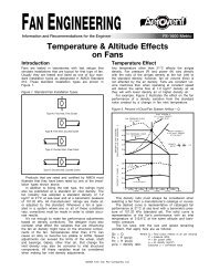
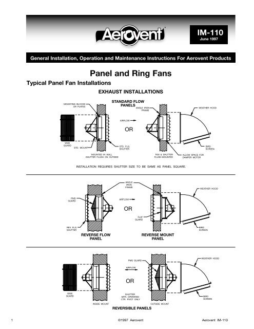
®<strong>IM</strong>-<strong>110</strong>June 1997General Installation, Operation <strong>and</strong> Maintenance Instructions For <strong>Aerovent</strong> Products<strong>Panel</strong> <strong>and</strong> <strong>Ring</strong> <strong>Fans</strong>Typical <strong>Panel</strong> Fan InstallationsEXHAUST INSTALLATIONSMOUNTING BLOCKSOR PLATESSTANDARD FLOWPANELSANGLE IRONFRAMEWEATHER HOODAIRFLOWORWWIIGUARDSTD. MOUNTSTD. FLG.SHUTTERBIRDSCREENMOUNTED IN WALLSHUTTER FLUSH ON OUTSIDEFAN & SHUTTERFLUSH-MOUNTEDALLOW SPACE FORDAMPER MOTORINSTALLATION REQUIRES SHUTTER SIZE TO BE SAME AS PANEL SQUARE.ANGLEIRONFRAMEWEATHER HOODPMSGUARDAIRFLOWORFLATGUARDREV. FLG.SHUTTERREVERSE FLOWPANELREVERSE MOUNTPANELBIRDSCREENPMS GUARDWEATHER HOODAIRFLOWORWWIIGUARDSHUTTERMTR. OPERATEDCTR. PIVOT ONLYBIRDSCREENINSIDE MOUNTREVERSIBLE PANELSOUTSIDE MOUNT1 ©1997 <strong>Aerovent</strong><strong>Aerovent</strong> <strong>IM</strong>-<strong>110</strong>
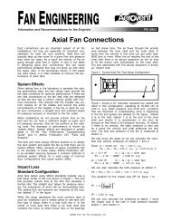
INSTALLATIONS USING MOUNTING ADAPTORSAIRFLOWAUTOMATICSHUTTERAIRFLOWAUTOMATICSHUTTERSTANDARD MOUNTALTERNATE MOUNTSTANDARD CONSTRUCTIONNOTE:ALL INSTALLATIONS SHOWNUSE SAME SIZE SHUTTERS &HOODS AS FAN SIZE.(REVERSIBLE)AIRFLOW(REVERSE FLOW)AIRFLOWCENTER-PIVOTMOTOR-OPERATEDSHUTTERSAIRFLOWRECOMMENDED MOUNTRECOMMENDED MOUNT(REVERSE CONSTRUCTION)ALTERNATE SOLUTIONSCENTER-PIVOTEDMOTOR-OPERATEDSHUTTERFLATGUARDAUTOMATICSHUTTERAIRFLOWAUTOMATICSHUTTEREXHAUST W/MTG. ADAPTORAIRFLOWAIRFLOWOUTSIDEOUTSIDESUPPLYARRANGEMENTEXHAUSTARRANGEMENTAIRFLOWCENTER-PIVOTEDMOTOR-OPERATEDSHUTTERSUPPLY W/WALL HOUSING2 <strong>Aerovent</strong> <strong>IM</strong>-<strong>110</strong>
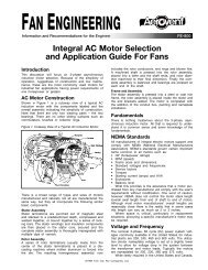
Typical <strong>Ring</strong> Fan InstallationsSTANDARD FLOWAIRFLOWFAN MOUNTEDFLUSH TO WALLFAN MOUNTEDTO DUCTWORKAIR-FLOWAIR-FLOWSTD.SHUTTERWALLSTD. FLOW RING FANW/MTG. PLATE, ROUNDPROP SIDE GUARD &SPLIT WIRE GUARDALTERNATEWMF GUARDREPLACESSPLIT WIREGUARDMOUNTSTO WALLWEATHERHOODW/BIRD SCREENSTD.SHUTTERWALLSTD. FLOW RING FANW/MTG. PLATE, ROUNDPROP SIDE GUARD &SPLIT WIRE GUARDALTERNATEWMF GUARDREPLACESSPLIT WIREGUARDMOUNTSTO WALLREVERSE CONSTRUCTIONAIR-FLOWREV. FLANGECENTER-PIVOTEDMOTOR-OPERATEDSHUTTERWALLREVERSEFLANGEMOUNTINGADAPTORREV. CONSTRUCTIONRING FAN W/MTG.PLATE, ROUNDGUARD & SPLITWIRE GUARDALTERNATEWMF GUARDREPLACESSPLIT WIREGUARDMOUNTSTO WALLREVERSE FLOW OR REVERSIBLEAIR-FLOWWEATHERHOODW/ BIRD SCREENCENTER-PIVOTMOTOR-OPERATEDSHUTTERWALLREVERSE FLOWOR REVERSIBLERING FAN W/MTG.PLATE, ROUNDGUARD & SPLITWIRE GUARDALTERNATEWMF GUARDREPLACESSPLIT WIREGUARDMOUNTSTO WALL3 <strong>Aerovent</strong> <strong>IM</strong>-<strong>110</strong>
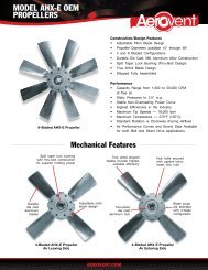
Rear Wire Guard (WWII) (Motorside)For <strong>Panel</strong> <strong>Fans</strong>PARTS(1) Rear <strong>Panel</strong>(4) Side <strong>Panel</strong>s(16) or (24) Hex Head Locknuts(16) or (24) 5 ∕16" x 1" Hex Head Capscrews(32) or (48) 3 ∕8" I.D. Flat WashersASSEMBLY1. Bolt three sides of guard to rear panel using5∕16" capscrews, nuts <strong>and</strong> flat washers.2. Bolt partially assembled guard to panel fanusing capscrews, nuts <strong>and</strong> flat washers.3. Arrange for electrical hook-up to fan motor. Twomethods may be used:a. Drill out hole in fan panel <strong>and</strong> route wire orconduit through opening.Round Motorside Basket Guard– OR –b. Bend or cut side panel wire guard <strong>and</strong> routewire or conduit through opening.4. Assemble fourth side to guard <strong>and</strong> panel, slidingalong conduit or wiring if routing throughguard.5. Securely tighten all locknuts.Cleaning PropellersThe propeller in an axial flow fan must be keptreasonably clean if it is to perform properly. <strong>Fans</strong>h<strong>and</strong>ling fresh air for ventilating purposes will seldomneed cleaning. <strong>Fans</strong> exhausting process airshould be cleaned as required. Dirt or chemicaldeposits will usually build up on a propeller evenly<strong>and</strong> they present no problem to performance oroperation until they become thick enough to breakaway in crust-like pieces. When this happens, thepropeller may be thrown out of balance <strong>and</strong> theresulting vibration could be serious. Accumula-tionsof deposits should be removed by solvent cleaningor scraping. If the propeller has been coated, becareful not to cut through the protective covering.Care <strong>and</strong> MaintenanceRegular <strong>and</strong> systematic inspection of all fanparts is a necessity for good fan maintenance.A general installation <strong>and</strong> maintenance brochure(<strong>IM</strong> 100) has been supplied with thisshipment. It includes fan <strong>and</strong> motor bearinglubrication, care <strong>and</strong> replacement of V-beltdrives <strong>and</strong> taperlock bushing instructions.Basket Guard<strong>Ring</strong> FanAttachGuardTo Wall4 MountingHolesCAUTION: Recommended distance between fan blade <strong>and</strong>shutter is approximately equal to 1 ⁄3 of the fan’s diameter.®4MWG06/11www.aerovent.com5959 Trenton Lane N | Minneapolis, MN 55442 | Phone: 763-551-7500 | Fax: 763-551-7501