Temperature and Altitude Effects on Fans - Aerovent
Temperature and Altitude Effects on Fans - Aerovent
Temperature and Altitude Effects on Fans - Aerovent

You also want an ePaper? Increase the reach of your titles
YUMPU automatically turns print PDFs into web optimized ePapers that Google loves.
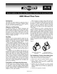
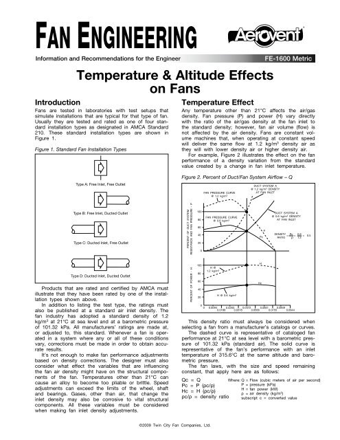
FAN ENGINEERING®Informati<strong>on</strong> <str<strong>on</strong>g>and</str<strong>on</strong>g> Recommendati<strong>on</strong>s for the Engineer<str<strong>on</strong>g>Temperature</str<strong>on</strong>g> & <str<strong>on</strong>g>Altitude</str<strong>on</strong>g> <str<strong>on</strong>g>Effects</str<strong>on</strong>g><strong>on</strong> <strong>Fans</strong>Introducti<strong>on</strong><strong>Fans</strong> are tested in laboratories with test setups thatsimulate installati<strong>on</strong>s that are typical for that type of fan.Usually they are tested <str<strong>on</strong>g>and</str<strong>on</strong>g> rated as <strong>on</strong>e of four st<str<strong>on</strong>g>and</str<strong>on</strong>g>ardinstallati<strong>on</strong> types as designated in AMCA St<str<strong>on</strong>g>and</str<strong>on</strong>g>ard210. These st<str<strong>on</strong>g>and</str<strong>on</strong>g>ard installati<strong>on</strong> types are shown inFigure 1.Figure 1. St<str<strong>on</strong>g>and</str<strong>on</strong>g>ard Fan Installati<strong>on</strong> TypesType A: Free Inlet, Free OutletType B: Free Inlet, Ducted OutletType C: Ducted Inlet, Free OutletType D: Ducted Inlet, Ducted OutletProducts that are rated <str<strong>on</strong>g>and</str<strong>on</strong>g> certified by AMCA mustillustrate that they have been rated by <strong>on</strong>e of the installati<strong>on</strong>types shown above.In additi<strong>on</strong> to listing the test type, the ratings mustalso be published at a st<str<strong>on</strong>g>and</str<strong>on</strong>g>ard air inlet density. Thefan industry has adopted a st<str<strong>on</strong>g>and</str<strong>on</strong>g>ard density of 1.2kg/m 3 at 21°C at sea level <str<strong>on</strong>g>and</str<strong>on</strong>g> at a barometric pressureof 101.32 kPa. All manufacturers’ ratings are made at,or adjusted to, this st<str<strong>on</strong>g>and</str<strong>on</strong>g>ard. Whenever a fan is operatedin a system where any or all of these c<strong>on</strong>diti<strong>on</strong>svary, correcti<strong>on</strong>s must be made in order to obtain accurateresults.It’s not enough to make fan performance adjustmentsbased <strong>on</strong> density correcti<strong>on</strong>s. The designer must alsoc<strong>on</strong>sider what effect the variables that are influencingthe fan air density might have <strong>on</strong> the structural comp<strong>on</strong>entsof the fan. <str<strong>on</strong>g>Temperature</str<strong>on</strong>g>s other than 21°C cancause an alloy to become too pliable or brittle. Speedadjustments can exceed the limits of the wheel, shaft<str<strong>on</strong>g>and</str<strong>on</strong>g> bearings. Gases, other than air, that change theinlet density may also be corrosive to vital structuralcomp<strong>on</strong>ents. All these variables must be c<strong>on</strong>sideredwhen making fan inlet density adjustments.<str<strong>on</strong>g>Temperature</str<strong>on</strong>g> EffectAny temperature other than 21°C affects the air/gasdensity. Fan pressure (P) <str<strong>on</strong>g>and</str<strong>on</strong>g> power (H) vary directlywith the ratio of the air/gas density at the fan inlet tothe st<str<strong>on</strong>g>and</str<strong>on</strong>g>ard density; however, fan air volume (flow) isnot affected by the air density. <strong>Fans</strong> are c<strong>on</strong>stant volumemachines that, when operating at c<strong>on</strong>stant speedwill deliver the same flow at 1.2 kg/m 3 density air asthey will with lower density air or higher density air.For example, Figure 2 illustrates the effect <strong>on</strong> the fanperformance of a density variati<strong>on</strong> from the st<str<strong>on</strong>g>and</str<strong>on</strong>g>ardvalue created by a change in fan inlet temperature.Figure 2. Percent of Duct/Fan System Airflow – QPERCENT OF DUCT SYSTEMRESISTANCE AND FAN PRESSURE - PPERCENT OF POWER - H100806040201008060402000FAN PRESSURE CURVE@ 1.2 kg/m 3FAN PRESSURE CURVE@ 0.6 kg/m 3H @1.2 kg/m 3H @ 0.6 kg/m 30 0.0094 0.0283 0.0472 0.0661 0.08490.0189 0.0378 0.0566 0.0755 0.0944This density ratio must always be c<strong>on</strong>sidered whenselecting a fan from a manufacturer’s catalogs or curves.The dashed curve is representative of cataloged fanperformance at 21°C at sea level with a barometric pressureof 101.32 kPa (st<str<strong>on</strong>g>and</str<strong>on</strong>g>ard air). The solid curve isrepresentative of the fan’s performance with an inlettemperature of 315.6°C at the same altitude <str<strong>on</strong>g>and</str<strong>on</strong>g> barometricpressure.The fan laws, with the size <str<strong>on</strong>g>and</str<strong>on</strong>g> speed remainingc<strong>on</strong>stant, that apply here are as follows:Qc = QPc = P (ρc/ρ)Hc = H (ρc/ρ)ρc/ρ = density ratioDUCT SYSTEM A@ 1.2 kg/m 3 DENSITYAT FAN INLETPPcHHcFE-1600 MetricDUCT SYSTEM A@ 0.6 kg/m 3 DENSITYAT FAN INLETDENSITY =r c =0.6 = 0.5RATIO r 1.2Where: Q = Flow (cubic meters of air per sec<strong>on</strong>d)P = pressure (kPa)H = fan power (kW)ρ = air density (kg/m 3 )subscript c = c<strong>on</strong>verted value©2009 Twin City Fan Companies, Ltd.
So how do we determine the air density for temperaturesother than 21°C? One way would be to calculateit using absolute temperatures, absolute pressures <str<strong>on</strong>g>and</str<strong>on</strong>g>barometric pressure, or we could simply refer to Table1 where it’s been c<strong>on</strong>veniently worked out for a rangeof temperatures at sea level.Table 1. Correcti<strong>on</strong>s for <str<strong>on</strong>g>Temperature</str<strong>on</strong>g> at Sea LevelAIRAIRTEMPERATURE FACTOR TEMPERATURE FACTOR(°C)(°C)–45.6 0.77 135.0 1.39–31.7 0.82 148.9 1.43–17.8 0.87 162.7 1.48–6.6 0.91 176.7 1.534.4 0.94 190.6 1.5815.6 0.98 204.4 1.6221.1 1.00 232.2 1.7226.7 1.02 260.0 1.8137.8 1.06 287.8 1.9148.9 1.09 315.6 2.0060.0 1.13 343.3 2.0971.1 1.17 371.1 2.1982.2 1.21 398.9 2.2893.3 1.25 426.7 2.38107.2 1.29 482.2 2.56121.1 1.34 537.8 2.76Actually, these factors are used directly to determinethe corrected fan performance. The factor is equal tothe fan’s rating density (st<str<strong>on</strong>g>and</str<strong>on</strong>g>ard air) divided by theactual air density at the fan inlet.Factor =1.2 kg/m3ρSo if the dry air density corresp<strong>on</strong>ding to an air temperatureother than 21°C is desired, it can be calculatedby simply dividing 1.2 by the factor.Fan densities may vary from st<str<strong>on</strong>g>and</str<strong>on</strong>g>ard for reas<strong>on</strong>sother than temperature <str<strong>on</strong>g>and</str<strong>on</strong>g> altitude. Moisture, gas, or amixture of gases other than air are a few possibilities.For these cases it will be necessary to obtain theactual density of the inlet gas stream by some otherreference material. The factor can then be obtained bysubstituting the new density for ρ.Example 1: A fan is required to deliver 7.08 m 3 /s against0.75 kPa SP (static pressure). The fan is to operate at176.7°C. This fan would be selected from a manufacturer’sst<str<strong>on</strong>g>and</str<strong>on</strong>g>ard rating table or curve for 7.08 m 3 /s at0.75 kPa SP at 21°C <str<strong>on</strong>g>and</str<strong>on</strong>g> would operate at 1,621 RPM<str<strong>on</strong>g>and</str<strong>on</strong>g> require 9.13 kW.To determine the fan’s performance at 176.7°C, simplydivide the SP <str<strong>on</strong>g>and</str<strong>on</strong>g> power by the factor from Table 1. Thefactor for 176.7°C is 1.53; therefore the operating static pressure<str<strong>on</strong>g>and</str<strong>on</strong>g> power dem<str<strong>on</strong>g>and</str<strong>on</strong>g> would be as follows:0.75 kPa SP 9.13 kW = 0.49 kPa SP = 5.97 kW1.53 1.53Although the fan RPM is within the speed rangespecified in the performance tables, the impeller safespeed needs to be verified for operati<strong>on</strong> at the elevatedtemperature. Most fan manufacturers will list safe speedfactors for operati<strong>on</strong> at elevated temperatures in the fancatalog <str<strong>on</strong>g>and</str<strong>on</strong>g> in their selecti<strong>on</strong> software.Cauti<strong>on</strong> is required when selecting the motor. Fromthe power dem<str<strong>on</strong>g>and</str<strong>on</strong>g> calculati<strong>on</strong> it appears that either a5.5 or a 7.5 kW motor could be used. But perhaps themotor selecti<strong>on</strong> should be based <strong>on</strong> a cold start of 9.13kW, to allow the fan to start before the air warms up.In this case the fan would require a 11.5 kW motor. Analternative to a larger motor, depending <strong>on</strong> the fan’spower dem<str<strong>on</strong>g>and</str<strong>on</strong>g> characteristics, could be a shutoff damperthat would not open until the air is up to temperature.For this particular fan, the shutoff power requirement is4.47 kW at st<str<strong>on</strong>g>and</str<strong>on</strong>g>ard c<strong>on</strong>diti<strong>on</strong>s.Example 2: Let us look at Example 1 another way.Suppose the request is for a fan to deliver 7.08 m 3 /sagainst 0.75 kPa SP at 176.7°C. In this case the designeris asking for a fan to develop the 0.75 kPa SP at176.7°C inlet temperature. In order to select the fan fromthe 21°F st<str<strong>on</strong>g>and</str<strong>on</strong>g>ard performance tables, we must firstc<strong>on</strong>vert the static pressure at 176.7°C to 21°C. Weaccomplish this by the factor established in Example 1.0.75 kPa SP x 1.53 = 1.15 kPa SPSo for this example, if we select the same fan model,our new requirements are for 7.08 m 3 /s at 1.15 kPa SPat 21°C. The fan would operate at 1,742 RPM <str<strong>on</strong>g>and</str<strong>on</strong>g>require 12.07 kW. It then follows that the operatingc<strong>on</strong>diti<strong>on</strong>s at 176.7°C would be as follows:1.15 kPa SP = 0.75 kPa SP <str<strong>on</strong>g>and</str<strong>on</strong>g> 12.07 kW = 7.89 kW1.53 1.53Flow <str<strong>on</strong>g>and</str<strong>on</strong>g> RPM would not change. And again, check themaximum speed limitati<strong>on</strong>s of the impeller <str<strong>on</strong>g>and</str<strong>on</strong>g> propermotor size for the cold starts.Also, keep the following in mind when using temperaturecorrecti<strong>on</strong> factors:1. At temperatures higher than st<str<strong>on</strong>g>and</str<strong>on</strong>g>ard air (21°C) theair density is less (lighter air); therefore both the pressure<str<strong>on</strong>g>and</str<strong>on</strong>g> power dem<str<strong>on</strong>g>and</str<strong>on</strong>g> will be less.2. At temperatures lower than st<str<strong>on</strong>g>and</str<strong>on</strong>g>ard air the air densityis greater (heavier air); therefore both the pressure<str<strong>on</strong>g>and</str<strong>on</strong>g> power dem<str<strong>on</strong>g>and</str<strong>on</strong>g> will be more.<str<strong>on</strong>g>Altitude</str<strong>on</strong>g> Effect<strong>Fans</strong> operating at some altitude above sea level aresimilar to fans operating above 21°C. The higher thealtitude the less dense (lighter) the air. <str<strong>on</strong>g>Altitude</str<strong>on</strong>g> correcti<strong>on</strong>factors for 21°C air are listed in Table 2. Note that thesecorrecti<strong>on</strong>s corresp<strong>on</strong>d to average barometric pressureat the stated altitude. Actual c<strong>on</strong>diti<strong>on</strong>s will vary with theweather.Table 2. Correcti<strong>on</strong>s for <str<strong>on</strong>g>Altitude</str<strong>on</strong>g> at 21°C AirALTITUDE (M) FACTOR ALTITUDE (M) FACTOR0.0 1.00 1,524.0 1.20152.4 1.02 1,676.4 1.22304.8 1.04 1,828.8 1.25457.2 1.06 1,981.2 1.27609.6 1.08 2,133.6 1.30762.0 1.10 2,286.0 1.32914.4 1.12 2,438.4 1.351,066.8 1.14 2,590.8 1.371,219.2 1.16 2,743.2 1.401,371.6 1.18 3,048.0 1.45Example 3: Select a fan to deliver 4.01 m 3 /s at 0.62 kPaSP at 1,676.4 m elevati<strong>on</strong>. Since no temperature is givenit will be assumed to be 21°C. From Table 2, the factorfor 1,676.4 m elevati<strong>on</strong> is 1.22. C<strong>on</strong>verting the staticpressure to sea level to use the manufacturer’s performancetables results in: SP = 1.22 x 0.62 kPa SP =0.76 kPa SP at sea level <str<strong>on</strong>g>and</str<strong>on</strong>g> 21°C. Selecting a fan for4.01 m3/s at 0.76 kPa SP results in an RPM of 1,173<str<strong>on</strong>g>and</str<strong>on</strong>g> 3.94 kW at sea level with 21°C entering air temperature.At the operating c<strong>on</strong>diti<strong>on</strong>s of 1,676.4 m elevati<strong>on</strong>the SP <str<strong>on</strong>g>and</str<strong>on</strong>g> power dem<str<strong>on</strong>g>and</str<strong>on</strong>g> would be corrected to:0.76 kPa SP 3.94 kW = 0.62 kPa SP = 3.23 kW1.22 1.22Flow <str<strong>on</strong>g>and</str<strong>on</strong>g> RPM would not change. C<strong>on</strong>firm that the RPMis within published speed limits. The motor power shouldbe okay because the temperature does not vary <str<strong>on</strong>g>and</str<strong>on</strong>g> theelevati<strong>on</strong> cannot change.2Fan Engineering FE-1600-Metric
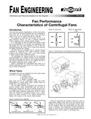
<str<strong>on</strong>g>Temperature</str<strong>on</strong>g> <str<strong>on</strong>g>and</str<strong>on</strong>g> <str<strong>on</strong>g>Altitude</str<strong>on</strong>g> EffectWhen both temperature <str<strong>on</strong>g>and</str<strong>on</strong>g> elevati<strong>on</strong> changes are present,the air density must be modified by a factor fromboth Tables 1 <str<strong>on</strong>g>and</str<strong>on</strong>g> 2. An alternative to this would be touse a single density ratio number such as can be foundin Figure 3.Figure 3. Air Density Ratios at Various <str<strong>on</strong>g>Altitude</str<strong>on</strong>g>s<str<strong>on</strong>g>and</str<strong>on</strong>g> <str<strong>on</strong>g>Temperature</str<strong>on</strong>g>sTEMPERATURE (C)3002752502252001751501251007550250-25-50ALTITUDE IN METERS3,0002,0002,50005001,0001,500-750.3 0.4 0.5 0.6 0.7 0.8 0.9 1.0 1.1 1.2 1.3 1.4 1.5DENSITY RATIOExample 4: Select a fan to deliver 4.01 m 3 /s at 0.62kPa SP at 1,676.4 m elevati<strong>on</strong> at 121.1°C. From Table1 the factor for 121.1°C is 1.34 <str<strong>on</strong>g>and</str<strong>on</strong>g> from Table 2 thefactor for 1,676.4 m elevati<strong>on</strong> is 1.22. The overall factoris obtained by multiplying these factors: 1.34 x 1.22 =1.63. To use a fan manufacturer’s performance tables,c<strong>on</strong>vert the SP to st<str<strong>on</strong>g>and</str<strong>on</strong>g>ard air:0.62 kPa SP x 1.63 factor = 1.01 kPa SPThe fan will be selected for 4.01 m 3 /s at 1.01 kPa SP<str<strong>on</strong>g>and</str<strong>on</strong>g> will operate at 1,287 RPM, 5.19 kW. C<strong>on</strong>verting tooperating c<strong>on</strong>diti<strong>on</strong>s results in:1.01 kPa SP 5.19 kW = 0.62 kPa SP = 3.18 kW1.63 1.63And again, flow <str<strong>on</strong>g>and</str<strong>on</strong>g> RPM will not change. Also, if thefan is to start cold, it will still be at 1,676.4 m elevati<strong>on</strong>.Therefore, to obtain the “cold” power dem<str<strong>on</strong>g>and</str<strong>on</strong>g>, divide thest<str<strong>on</strong>g>and</str<strong>on</strong>g>ard air power dem<str<strong>on</strong>g>and</str<strong>on</strong>g> by the altitude factor <strong>on</strong>ly.5.19 kW = 4.25 kW1.22Identical results can also be achieved by using Figure3. Locate the temperature <strong>on</strong> the left-h<str<strong>on</strong>g>and</str<strong>on</strong>g> scale <str<strong>on</strong>g>and</str<strong>on</strong>g>proceed horiz<strong>on</strong>tally to the intersect of the altitude curve,<str<strong>on</strong>g>and</str<strong>on</strong>g> then follow it vertically down to the density ratio atthe bottom of the graph. For a temperature of 121.1°C<str<strong>on</strong>g>and</str<strong>on</strong>g> an elevati<strong>on</strong> of 1,676.4 m, we read a density ratioof 0.613. The density ratio is simply the reciprocal ofthe factor.1= 0.613 density ratio (DR)1.63 factorActual Cubic Meters per Sec<strong>on</strong>d vsNormal Cubic Meters per Sec<strong>on</strong>dThese two terms are comm<strong>on</strong>ly used in design work,<str<strong>on</strong>g>and</str<strong>on</strong>g> they should not be c<strong>on</strong>fused as this greatly influencesthe fan selecti<strong>on</strong>.Actual cubic meters per sec<strong>on</strong>d — Represents the volumeof gas flowing anywhere in the system independentof its density. Cubic meters per sec<strong>on</strong>d is the value thatis used when selecting a fan.Normal cubic meters per sec<strong>on</strong>d — Air volume correctedto st<str<strong>on</strong>g>and</str<strong>on</strong>g>ard density c<strong>on</strong>diti<strong>on</strong>s. This term is comm<strong>on</strong>lyused when a given weight rate of flow is required.For example, to determine the normal cubic meters persec<strong>on</strong>d of a fan delivering 4.72 m 3 /s at 315.6°C, wewould multiply the m 3 /s by the density ratio or divide itby the factor.4.72 m 3 0.60 kg/m/s x3 = 2.36 Nm3 /s1.20 kg/m 3Selecting a fan when normal flow (Nm³/s) is specifiedrequires us to calculate the actual flow (m³/s). If the fanwas specified for 4.72 m 3 /s at 315.6°C, then an equivalentweight rate of flow is desired at 315.6°C.4.72 m 3 1.20 kg/m/s x3= 9.44 kg/m0.60 kg/m 33Select the fan for 9.44 m 3 /s.Inlet Sucti<strong>on</strong> EffectA comm<strong>on</strong> influence <strong>on</strong> density, especially <strong>on</strong> exhaustsystems, is sucti<strong>on</strong>. When system resistance is placed<strong>on</strong> a fan’s inlet, the sucti<strong>on</strong> creates a partial vacuum atthe inlet. This negative inlet pressure (partial vacuum)lowers the barometric pressure at the inlet <str<strong>on</strong>g>and</str<strong>on</strong>g> thereforethe inlet density. This correcti<strong>on</strong> is rarely accounted forunless the sucti<strong>on</strong> pressure exceeds 2.49 kPa SP. Inany event, this negative inlet pressure effect can beaccounted for in the following manner:Inlet density (kg/m 3 ) =Atm. Press. (kPa) + Inlet SP (kPa)Gas density (kg/m³) xAtm. Press. (kPa)— or —Atm. Press. (kPa) + Inlet SP (kPa)DR (inlet) = DR (gas) xAtm. Press. (kPa)Where: Atm. Press. = atmospheric pressure = 101.32 kPa(at other than sea level divide 101.32 by the altitudefactor to get the atmospheric pressure)Density of st<str<strong>on</strong>g>and</str<strong>on</strong>g>ard air = 1.2 kg/m 3Density ratio (DR) of st<str<strong>on</strong>g>and</str<strong>on</strong>g>ard air = 1.00Inlet SP is normally a negative number.Example 5: A fan is to deliver 5.07 m³/s at 5.47 kPa SP.4.97 kPa of this pressure is at the fan inlet.DR (inlet) = 1.00 x 101.32 + (–4.97) = 0.951101.32SP = 5.47 kPa ÷ 0.951 = 5.75 kPa SP at 21°CTherefore, a fan is selected for 5.07 m³/s at 5.75 kPaSP which results in an RPM of 1,873 <str<strong>on</strong>g>and</str<strong>on</strong>g> a powerdem<str<strong>on</strong>g>and</str<strong>on</strong>g> of 47.58 kW. The corrected power dem<str<strong>on</strong>g>and</str<strong>on</strong>g>would then equal 47.58 x 0.951 or 43.30 kW.3Fan Engineering FE-1600-Metric
Example 6: If c<strong>on</strong>diti<strong>on</strong>s were at 93.3°C instead of st<str<strong>on</strong>g>and</str<strong>on</strong>g>ardair, then:DR (inlet) = 0.80 x 101.32 + (–4.97) = 0.761101.32SP = 5.47 kPa ÷ 0.761 = 7.19 kPa SP at 93.3°CThe fan would now be selected for 5.07 m³/s at 7.19kPa SP resulting in a speed of 2,073 RPM <str<strong>on</strong>g>and</str<strong>on</strong>g> a powerdem<str<strong>on</strong>g>and</str<strong>on</strong>g> of 59.39 kW. The corrected power dem<str<strong>on</strong>g>and</str<strong>on</strong>g>would then equal 59.39 kW x 0.761 or 45.20 kW.Both selecti<strong>on</strong>s could be operated with a 45 kWmotor; however, if the 93.3°C fan were to be subjectedto cold starts without a shutoff damper, then a 75 kWmotor would be required.®<strong>Aerovent</strong> | www.aerovent.com5959 Trent<strong>on</strong> Lane N | Minneapolis, MN 55442 | Ph<strong>on</strong>e: 763-551-7500 | Fax: 763-551-7501