Vaneaxial Fans Axiad II Adjustable Pitch Airfoil (Model ... - Aerovent
Vaneaxial Fans Axiad II Adjustable Pitch Airfoil (Model ... - Aerovent
Vaneaxial Fans Axiad II Adjustable Pitch Airfoil (Model ... - Aerovent

You also want an ePaper? Increase the reach of your titles
YUMPU automatically turns print PDFs into web optimized ePapers that Google loves.
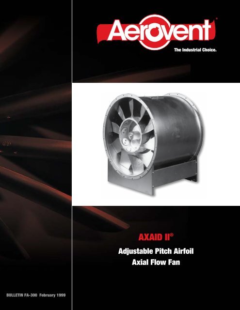
®The Industrial Choice.AXAID <strong>II</strong> ®<strong>Adjustable</strong> <strong>Pitch</strong> <strong>Airfoil</strong>Axial Flow FanBULLETIN FA-300 February 1999
Features• Available in 11 sizes from 22" to 55" diameter.• Airflows from 2000 to 100,000 CFM\• Static pressure capabilities to 14" w.g.<strong>Aerovent</strong> is proud to introduce the AXIAD <strong>II</strong> fan. This fanis the culmination of a design effort to produce a low noiseadjustable pitch axial flow fan with high efficiency, compactsize and simple blade adjustment.The AXIAD <strong>II</strong> fan has been researched both aerodynamicallyand acoustically in AMCA approved computerizedlaboratories. The result is a fan that produces low soundpower level when compared to other standard axial flow andcentrifugal fans. The compact size occupies less space thancomparable centrifugal fans and the straight-through airflowdesign provides installation savings.The blade adjustment mechanism is of simple yet strongdesign consisting of two bolts and a clamp. To change pitchangle it is necessary merely to loosen the bolts, turn the bladeto the proper angle, and retighten the bolts. This provides easeof adjustment and assurance that position will not change.The hub of the fan is index marked for each blade angle. Thecorrect blade position is indicated on the performance curvesand corresponds to the hub markings.The adjustable pitch blade feature permits easy systembalancing or adjustment for unpredictable duct losses. It alsopermits changing fan characteristics to match changing jobconditions. Since the blades can be changed in pitch approximately35°, a wide variation in performance is possible.Compared with airfoil centrifugal or tubular centrifugalfans, AXIAD <strong>II</strong> fans are much lighter in weight, requiring onlysimple isolators instead of concrete inertia bases. AXIAD <strong>II</strong>fans are also more compact, occupying considerably less spacethan centrifugal fans.The standard AXIAD <strong>II</strong> fan has an internal direct connectedelectric drive motor. A variety of full load speeds ispossible, giving wide size selection possibilities. The directconnected motor also eliminates cumbersome V-belt drives,and the adjustable pitch blade design eliminates changing pulleysizes to obtain capacity changes.Because the AXIAD <strong>II</strong> rotor is a high efficiency design, thefan can be supplied with or without the discharge vane section.This feature allows further refinements in fan selection, makingeconomy in first cost and operating expense a certainty.Without VaneWith Vane SectionContentsGuide to AXIAD <strong>II</strong> Performance Charts .............4AXIAD <strong>II</strong> Nomenclature ..........................4Fan Selection ....................................5Fan Curve Sizes: 056. ..........................6063. ..........................7071. .......................8-10080. ......................11-14090. ......................15-21100. ......................22-28Fan Curve Sizes: 112 ...................... 29-34125 ...................... 35-40140 ...................... 41-42Sound Data Corrections . ...................... 42-44Guide to Simplified Selection Charts & Tables. .......45Annular Velocity Charts ....................... 46-47Impact Loss and Velocity Pressure Curves ........ 48-49Dimensions ................................. 50-51®<strong>Aerovent</strong> certifies that the AXIAD <strong>II</strong> fans shown herein have been tested and rated in accordance with industry acceptedtest codes, and are guaranteed by the manufacturer to deliver rated performance.3 <strong>Aerovent</strong> Bulletin FA-300
Guide to AXIAD <strong>II</strong> Performance ChartsThis bulletin presents AXIAD <strong>II</strong> axial fan performance charts, which show in graphical form volume (CFM), pressure (in. w.g.),efficiency, blade position, and fan brake horsepower (BHP) relationships encountered in the most common AXIAD <strong>II</strong> fan, rotorand blade combinations operating at motor speeds associated with 60 Hertz operation (900, 1200, 1800, and 3600 RPM). Data onother sizes of fans and fans operating at different speeds is available from the factory.A typical AXIAD <strong>II</strong> performance chart is represented above. You will notice that the charts are presented on the basis of totalpressure. The pressure shown as total pressure is the sum of static pressure, velocity pressure, and impact pressure loss. Staticpressure is generally given, while velocity pressure and impact pressure loss are calculable by methods explained elsewhere in thisbrochure, and at greater length in other <strong>Aerovent</strong> publications.The operating point of a fan can be determined by knowing any two of the six parameters plotted in the fan charts. Generally,selections are made by establishing total pressure and reading across the total pressure line (in. w.g.) to the intersection with thevolume (CFM) line; and noting the blade position and efficiency. BHP is established by reading down the volume line to the previouslyestablished blade position, locating the brake horsepower by reading horizontally across the chart. In selecting an AXIAD <strong>II</strong>fan it is best to choose a size that will operate at a point that is in the vicinity of the maximum efficiency oval.An important consideration in fan selection is the relation of the selection point to the stall line. The stall area is located at theupper end of the blade angle lines and must be avoided. Fan operation in this area is unstable, producing vibration, hunting andsurging. To ensure avoiding the area, fan selections should use only 90% of the available pressure at the specified flow. Calculationof a system parabola will show that only by allowing this safety margin can an error involving underestimation of static pressurebe corrected by the relatively simple method of increasing blade angle.AXIAD <strong>II</strong> NomenclatureFTFA - 140 - 5 - 2 (+) 885 - MOTOR SPEEDFan SizeWith Vane Section, ( ) = Less VanesFull Bladed, if 1 = Half BladedHub Size will be 3 with 6 or 3 Blades4 with 8 or 4 Blades5 with 10 or 5 Blades4 <strong>Aerovent</strong> Bulletin FA-300
Fan SelectionStraight-Through Airflow in Any DirectionThe data presented in this manual allows the reader to arrive at a fan selection, starting with airflow, pressure, and downstream ductvelocity of the system. Generally, for any given set of the above conditions, there are a number of fans that are possible selections.The parameters for separating these selections are generally (1) brake horsepower, (2) acoustics, and (3) first cost.The table below shows nine possible selections to meet the conditions: 40,000 CFM, 2.5 inches static pressure, discharging intoa plenum at 500 feet per minute. It may be of value to the reader to use the selection pressure calculations, efficiency calculations,and brake horsepower calculations. The sound data shown here is presented on the fan curve, and this is correctable to octave bandreadings as shown on pages 42 through 44.The weight that the designer gives to each of the factors involved in selection is something that varies with each individualcase. One would note from perusing the data that fans number 1 and 2 are the most compact, fans number 3 and 4 are the leastexpensive, fans number 5 and 9 are the quietest, and fans number 8 and 9 take up the greatest amount of space and tend to be veryexpensive. Under normal circumstances we suggest that the designer, after thoroughly investigating the nine possibilities, wouldtend to narrow them down to fan number 3 versus fan number 5. In this case, the designer must balance a 10% HP savings and 6dB lower noise output of the FTFA-112-5-2 + with diffuser against a cost differential approximately 40% which favors the FTFA-112-4-1. The final selection should be the result of a thorough systematic cost analysis that your <strong>Aerovent</strong> representative will behappy to assist you with.ExampleGiven:Flow = 40,000 CFM Static Pressure = 2.5" w.g. Discharge Condition: into Plenum, V4 = 500 FPMFAN FAN VANETOTAL EFFICIENCYOVERALL RELATIVEOUTLET RPMBHPNO. FTFA SECTION PRESSURE PERCENT PWL COST1 100-3-2 NO CONE 1800 3.08 74 26.2 106 522 100-4-1 NO CONE 1800 3.20 71 28.4 109 533 112-4-1 NO CONE 1800 2.88 75.5 24.0 109 514 112-4-2 NO — 1800 3.50 77 28.8 109 505 112-5-2 YES DIFF 1200 2.98 85.5 21.9 103 816 125-4-2 YES DIFF 1200 2.72 78 22.0 106 767 125-5-2 YES — 1200 3.15 85 23.3 107 808 125-5-2 YES DIFF 1200 2.76 85.5 20.3 105 89®5 <strong>Aerovent</strong> Bulletin FA-300
Performance Data – FTFA 056-3-2+Performance at density of 0.075 lb./ft. 36 <strong>Aerovent</strong> Bulletin FA-300
Performance Data – FTFA 063-3-2+Performance at density of 0.075 lb./ft. 3 ®7 <strong>Aerovent</strong> Bulletin FA-300
Performance Data – FTFA 071-3-2Performance at density of 0.075 lb./ft. 38 <strong>Aerovent</strong> Bulletin FA-300
Performance Data – FTFA 071-3-2+Performance at density of 0.075 lb./ft. 3 ®9 <strong>Aerovent</strong> Bulletin FA-300
Performance Data – FTFA 071-4-2+Performance at density of 0.075 lb./ft. 310 <strong>Aerovent</strong> Bulletin FA-300
Performance Data – FTFA 080-3-1Performance at density of 0.075 lb./ft. 3 ®11 <strong>Aerovent</strong> Bulletin FA-300
Performance Data – FTFA 080-3-2Performance at density of 0.075 lb./ft. 312 <strong>Aerovent</strong> Bulletin FA-300
Performance Data – FTFA 080-3-2+Performance at density of 0.075 lb./ft. 3 ®13 <strong>Aerovent</strong> Bulletin FA-300
Performance Data – FTFA 080-4-2+Performance at density of 0.075 lb./ft. 314 <strong>Aerovent</strong> Bulletin FA-300
Performance Data – FTFA 090-3-1Performance at density of 0.075 lb./ft. 3 ®15 <strong>Aerovent</strong> Bulletin FA-300
Performance Data – FTFA 090-3-2Performance at density of 0.075 lb./ft. 316 <strong>Aerovent</strong> Bulletin FA-300
Performance Data – FTFA 090-3-2+Performance at density of 0.075 lb./ft. 3 ®17 <strong>Aerovent</strong> Bulletin FA-300
Performance Data – FTFA 090-4-1Performance at density of 0.075 lb./ft. 318 <strong>Aerovent</strong> Bulletin FA-300
Performance Data – FTFA 090-4-2Performance at density of 0.075 lb./ft. 3 ®19 <strong>Aerovent</strong> Bulletin FA-300
Performance Data – FTFA 090-4-2+Performance at density of 0.075 lb./ft. 320 <strong>Aerovent</strong> Bulletin FA-300
Performance Data – FTFA 090-5-2+Performance at density of 0.075 lb./ft. 3 ®21 <strong>Aerovent</strong> Bulletin FA-300
Performance Data – FTFA 100-3-1Performance at density of 0.075 lb./ft. 322 <strong>Aerovent</strong> Bulletin FA-300
Performance Data – FTFA 100-3-2Performance at density of 0.075 lb./ft. 3 ®23 <strong>Aerovent</strong> Bulletin FA-300
Performance Data – FTFA 100-3-2+Performance at density of 0.075 lb./ft. 324 <strong>Aerovent</strong> Bulletin FA-300
Performance Data – FTFA 100-4-1Performance at density of 0.075 lb./ft. 3 ®25 <strong>Aerovent</strong> Bulletin FA-300
Performance Data – FTFA 100-4-2Performance at density of 0.075 lb./ft. 326 <strong>Aerovent</strong> Bulletin FA-300
Performance Data – FTFA 100-4-2+Performance at density of 0.075 lb./ft. 3 ®27 <strong>Aerovent</strong> Bulletin FA-300
Performance Data – FTFA 100-5-2+Performance at density of 0.075 lb./ft. 328 <strong>Aerovent</strong> Bulletin FA-300
Performance Data – FTFA 112-4-1Performance at density of 0.075 lb./ft. 3 ®29 <strong>Aerovent</strong> Bulletin FA-300
Performance Data – FTFA 112-4-2Performance at density of 0.075 lb./ft. 330 <strong>Aerovent</strong> Bulletin FA-300
Performance Data – FTFA 112-4-2+Performance at density of 0.075 lb./ft. 3 ®31 <strong>Aerovent</strong> Bulletin FA-300
Performance Data – FTFA 112-5-1Performance at density of 0.075 lb./ft. 332 <strong>Aerovent</strong> Bulletin FA-300
Performance Data – FTFA 112-5-2Performance at density of 0.075 lb./ft. 3 ®33 <strong>Aerovent</strong> Bulletin FA-300
Performance Data – FTFA 112-5-2+Performance at density of 0.075 lb./ft. 334 <strong>Aerovent</strong> Bulletin FA-300
Performance Data – FTFA 125-4-1Performance at density of 0.075 lb./ft. 3 ®35 <strong>Aerovent</strong> Bulletin FA-300
Performance Data – FTFA 125-4-2Performance at density of 0.075 lb./ft. 336 <strong>Aerovent</strong> Bulletin FA-300
Performance Data – FTFA 125-4-2+Performance at density of 0.075 lb./ft. 3 ®37 <strong>Aerovent</strong> Bulletin FA-300
Performance Data – FTFA 125-5-1Performance at density of 0.075 lb./ft. 338 <strong>Aerovent</strong> Bulletin FA-300
Performance Data – FTFA 125-5-2Performance at density of 0.075 lb./ft. 3 ®39 <strong>Aerovent</strong> Bulletin FA-300
Performance Data – FTFA 125-5-2+Performance at density of 0.075 lb./ft. 340 <strong>Aerovent</strong> Bulletin FA-300
Performance Data – FTFA 140-5-1, 140-5-2Performance at density of 0.075 lb./ft. 3 ®41 <strong>Aerovent</strong> Bulletin FA-300
Performance Data – FTFA 140-5-2+Performance at density of 0.075 lb./ft. 3Sound Power Correction FactorsThe Correction Factors shown below are to be added to the total Sound Power found on the appropriate fan curve, (i.e. for090-3-2-885 RPM, 10,000 CFM, 0.7" total press. Lwt = 86 the correction at 250 Hz is — 7. Therefore the corrected PWLat 250 Hz = 79 dB.OCTAVE/BAND HERTZ CENTER FREQUENCYFAN RPM1/63 2/125 3/250 4/500 5/1000 6/2000 7/4000 8/8000056-3-2 (+) 885 — 10 — 6 — 6 — 6 — 14 — 18 — 21 — 30056-3-2 (+) 1180 — 11 — 5 — 7 — 6 — 13 — 17 — 20 — 28056-3-2 (+) 1760 — 12 — 6 — 8 — 6 — 12 — 15 — 18 — 25056-3-2 (+) 3500 — 12 — 9 — 6 — 6 — 12 — 13 — 15 — 22063-3-2 (+) 885 — 10 — 7 — 6 — 6 — 14 — 20 — 23 — 31063-3-2 (+) 1180 — 11 — 7 — 7 — 6 — 12 — 18 — 21 — 29063-3-2 (+) 1760 — 12 — 7 — 8 — 6 — 11 — 16 — 19 — 26063-3-2 (+) 3500 — 12 — 10 — 6 — 6 — 11 — 15 — 16 — 23071-3-2 ( ) 885 — 12 — 9 — 3 — 6 — 15 — 21 — 23 — 31071-3-2 (+) 885 — 12 — 9 — 5 — 6 — 15 — 21 — 25 — 33071-4-2 (+) 885 — 11 — 6 — 6 — 5 — 10 — 17 — 22 — 27071-3-2 ( ) 1180 — 13 — 8 — 4 — 6 — 14 — 19 — 21 — 30071-3-2 (+) 1180 — 13 — 7 — 6 — 6 — 14 — 19 — 23 — 32071-4-2 (+) 1180 — 12 — 7 — 7 — 5 — 9 — 15 — 20 — 26071-3-2 ( ) 1760 — 13 — 8 — 5 — 6 — 13 — 18 — 20 — 2742 <strong>Aerovent</strong> Bulletin FA-300
Sound Power Correction FactorsFANRPMOCTAVE/BAND HERTZ CENTER FREQUENCY1/63 2/125 3/250 4/500 5/1000 6/2000 7/4000 8/8000071-3-2 (+) 1760 — 13 — 7 — 7 — 6 — 13 — 18 — 22 — 29071-4-2 (+) 1760 — 12 — 7 — 8 — 5 — 8 — 14 — 19 — 23080-3-1 ( ) 885 — 7 — 8 — 4 — 6 — 12 — 18 — 23 — 25080-3-2 ( ) 885 — 12 — 9 — 5 — 6 — 12 — 18 — 21 — 28080-3-2 (+) 885 — 12 — 8 — 6 — 6 — 12 — 18 — 23 — 31080-4-2 (+) 885 — 11 — 6 — 6 — 5 — 10 — 17 — 22 — 27080-3-1 ( ) 1180 — 8 — 6 — 5 — 6 — 11 — 16 — 21 — 24080-3-2 ( ) 1180 — 13 — 7 — 6 — 6 — 11 — 16 — 19 — 27080-3-2 (+) 1180 — 13 — 6 — 7 — 6 — 11 — 16 — 21 — 30080-4-2 (+) 1180 — 12 — 7 — 7 — 5 — 9 — 15 — 20 — 26080-3-1 ( ) 1760 — 8 — 6 — 6 — 6 — 10 — 15 — 20 — 21080-3-2 ( ) 1760 — 13 — 7 — 7 — 6 — 10 — 15 — 18 — 24080-3-2 (+) 1760 — 13 — 6 — 8 — 6 — 10 — 15 — 20 — 27080-4-2 (+) 1760 — 12 — 7 — 8 — 5 — 8 — 14 — 19 — 23090-3-1 ( ) 885 — 7 — 7 — 5 — 5 — 12 — 17 — 22 — 23090-3-2 ( ) 885 — 12 — 7 — 7 — 5 — 11 — 17 — 20 — 26090-3-2 (+) 885 — 12 — 8 — 6 — 5 — 11 — 17 — 22 — 30090-4-1 ( ) 885 — 12 — 9 — 4 — 5 — 10 — 18 — 22 — 27090-4-2 ( ) 885 — 14 — 6 — 6 — 5 — 9 — 17 — 21 — 25090-4-2 (+) 885 — 11 — 5 — 6 — 5 — 10 — 17 — 22 — 27090-5-2 (+) 885 — 16 — 5 — 4 — 6 — 11 — 17 — 22 — 28090-3-1 ( ) 1180 — 8 — 5 — 6 — 5 — 11 — 15 — 20 — 22090-3-2 ( ) 1180 — 13 — 5 — 8 — 5 — 10 — 15 — 18 — 25090-3-2 (+) 1180 — 13 — 6 — 7 — 5 — 10 — 15 — 20 — 29090-4-1 ( ) 1180 — 13 — 10 — 5 — 5 — 9 — 16 — 20 — 26090-4-2 ( ) 1180 — 15 — 7 — 7 — 5 — 8 — 15 — 19 — 24090-4-2 (+) 1180 — 12 — 6 — 7 — 5 — 9 — 15 — 20 — 26090-5-2 (+) 1180 — 17 — 6 — 5 — 6 — 9 — 16 — 20 — 27090-3-1 ( ) 1760 — 8 — 5 — 7 — 5 — 10 — 14 — 19 — 19090-3-2 ( ) 1760 — 13 — 5 — 9 — 5 — 9 — 14 — 17 — 22090-3-2 (+) 1760 — 13 — 6 — 8 — 5 — 9 — 14 — 19 — 26090-4-1 ( ) 1760 — 13 — 10 — 6 — 5 — 8 — 15 — 19 — 23090-4-2 ( ) 1760 — 15 — 7 — 8 — 5 — 7 — 14 — 18 — 21090-4-2 (+) 1760 — 12 — 6 — 8 — 5 — 8 — 14 — 19 — 23090-5-2 (+) 1760 — 18 — 8 — 7 — 6 — 7 — 14 — 18 — 24100-3-1 ( ) 885 — 7 — 7 — 4 — 5 — 11 — 17 — 23 — 23100-3-2 ( ) 885 — 12 — 7 — 6 — 5 — 11 — 17 — 21 — 26100-3-2 (+) 885 — 12 — 8 — 6 — 5 — 11 — 17 — 22 — 30100-4-1 ( ) 885 — 12 — 10 — 4 — 5 — 10 — 18 — 22 — 27100-4-2 ( ) 885 — 14 — 8 — 6 — 5 — 9 — 17 — 21 — 25100-4-2 (+) 885 — 13 — 6 — 6 — 5 — 10 — 17 — 22 — 29100-5-2 (+) 885 — 16 — 5 — 14 — 6 — 11 — 17 — 22 — 28100-3-1 ( ) 1180 — 8 — 5 — 5 — 5 — 10 — 15 — 21 — 22100-3-2 ( ) 1180 — 13 — 5 — 7 — 5 — 10 — 15 — 19 — 25100-3-2 (+) 1180 — 13 — 6 — 7 — 5 — 10 — 15 — 20 — 29100-4-1 ( ) 1180 — 13 — 11 — 5 — 5 — 9 — 16 — 20 — 26100-4-2 ( ) 1180 — 15 — 9 — 7 — 5 — 8 — 15 — 19 — 24100-4-2 (+) 1180 — 14 — 7 — 7 — 5 — 9 — 15 — 20 — 28100-5-2 (+) 1180 — 17 — 6 — 5 — 6 — 9 — 16 — 20 — 27100-3-1 ( ) 1760 — 8 — 5 — 6 — 5 — 9 — 14 — 20 — 19100-3-2 ( ) 1760 — 13 — 5 — 8 — 5 — 9 — 14 — 18 — 22100-3-2 (+) 1760 — 13 — 6 — 8 — 5 — 9 — 14 — 19 — 26100-4-1 ( ) 1760 — 13 — 11 — 6 — 5 — 8 — 15 — 19 — 23100-4-2 ( ) 1760 — 15 — 9 — 8 — 5 — 7 — 14 — 18 — 21100-4-2 (+) 1760 — 14 — 7 — 8 — 5 — 8 — 14 — 19 — 25100-5-2 (+) 1760 — 18 — 8 — 7 — 6 — 7 — 14 — 18 — 24®43 <strong>Aerovent</strong> Bulletin FA-300
Sound Power Correction FactorsFANRPMOCTAVE/BAND HERTZ CENTER FREQUENCY1/63 2/125 3/250 4/500 5/1000 6/2000 7/4000 8/8000112-4-1 ( ) 885 — 12 — 11 — 4 — 4 — 10 — 17 — 21 — 27112-4-2 ( ) 885 — 15 — 9 — 6 — 3 — 9 — 15 — 20 — 25112-4-2 (+) 885 — 13 — 7 — 6 — 5 — 10 — 17 — 22 — 29112-5-1 ( ) 885 — 10 — 6 — 5 — 6 — 11 — 16 — 20 — 26112-5-2 ( ) 885 — 18 — 5 — 6 — 6 — 12 — 17 — 22 — 29112-5-2 (+) 885 — 16 — 6 — 4 — 5 — 11 — 17 — 22 — 29112-7-2 (+) 885 — 16 — 7 — 4 — 5 — 11 — 18 — 22 — 29112-4-1 ( ) 1180 — 13 — 12 — 5 — 4 — 9 — 15 — 19 — 26112-4-2 ( ) 1180 — 16 — 10 — 7 — 4 — 8 — 13 — 18 — 24112-4-2 (+) 1180 — 14 — 8 — 7 — 5 — 9 — 15 — 20 — 28112-5-1 ( ) 1180 — 12 — 7 — 5 — 6 — 9 — 15 — 19 — 24112-5-2 ( ) 1180 — 20 — 5 — 7 — 6 — 10 — 16 — 20 — 27112-5-2 (+) 1180 — 17 — 7 — 5 — 5 — 9 — 16 — 20 — 28112-7-2 (+) 1180 — 19 — 8 — 3 — 4 — 8 — 15 — 20 — 29112-4-1 ( ) 1760 — 13 — 12 — 6 — 4 — 8 — 14 — 18 — 23112-4-2 ( ) 1760 — 16 — 10 — 8 — 6 — 7 — 12 — 17 — 21112-4-2 (+) 1760 — 14 — 8 — 8 — 5 — 8 — 14 — 19 — 25112-5-1 ( ) 1760 — 12 — 7 — 7 — 6 — 7 — 13 — 17 — 21112-5-2 ( ) 1760 — 21 — 6 — 9 — 6 — 8 — 14 — 18 — 24112-5-2 (+) 1760 — 18 — 9 — 7 — 5 — 7 — 14 — 18 — 25125-4-1 ( ) 885 — 12 — 11 — 4 — 4 — 10 — 17 — 21 — 27125-4-2 ( ) 885 — 15 — 9 — 6 — 4 — 9 — 15 — 20 — 25125-4-2 (+) 885 — 13 — 7 — 6 — 5 — 10 — 17 — 22 — 29125-5-1 ( ) 885 — 10 — 6 — 5 — 6 — 11 — 16 — 20 — 26125-5-2 ( ) 885 — 18 — 5 — 6 — 6 — 12 — 17 — 22 — 29125-5-2 (+) 885 — 16 — 6 — 4 — 5 — 11 — 17 — 22 — 29125-4-1 ( ) 1180 — 13 — 12 — 5 — 4 — 9 — 15 — 19 — 26125-4-2 ( ) 1180 — 16 — 10 — 7 — 4 — 8 — 13 — 18 — 24125-4-2 (+) 1180 — 14 — 8 — 7 — 5 — 9 — 15 — 20 — 28125-5-1 ( ) 1180 — 12 — 7 — 5 — 6 — 9 — 15 — 19 — 24125-5-2 ( ) 1180 — 20 — 5 — 7 — 6 — 10 — 16 — 20 — 27125-5-2 (+) 1180 — 17 — 7 — 5 — 5 — 9 — 16 — 20 — 28125-4-1 ( ) 1760 — 13 — 12 — 6 — 4 — 8 — 14 — 18 — 23125-4-2 ( ) 1760 — 16 — 10 — 8 — 5 — 7 — 12 — 17 — 21125-4-2 (+) 1760 — 14 — 8 — 8 — 5 — 8 — 14 — 19 — 25125-5-1 ( ) 1760 — 12 — 7 — 7 — 6 — 7 — 13 — 17 — 21125-5-2 ( ) 1760 — 21 — 6 — 9 — 6 — 8 — 14 — 18 — 24125-5-2 (+) 1760 — 18 — 9 — 7 — 5 — 7 — 14 — 18 — 25140-5-1 ( ) 885 — 10 — 7 — 5 — 6 — 11 — 16 — 20 — 26140-5-2 ( ) 885 — 18 — 5 — 6 — 6 — 12 — 17 — 22 — 29140-5-2 (+) 885 — 16 — 6 — 4 — 5 — 11 — 17 — 22 — 29140-5-1 ( ) 1180 — 12 — 8 — 5 — 6 — 9 — 15 — 19 — 24140-5-2 ( ) 1180 — 20 — 5 — 7 — 6 — 10 — 16 — 20 — 27140-5-2 (+) 1180 — 17 — 7 — 5 — 5 — 9 — 16 — 20 — 2844 <strong>Aerovent</strong> Bulletin FA-300
Selection of AXIAD <strong>II</strong> Axial Flow <strong>Fans</strong> Using Simplified Selection Charts<strong>Vaneaxial</strong> fans are usually rated in terms of total pressure (pt), total pressure being the sum of the system static resistance (ps), plusthe velocity pressure (pv) in the duct leaving the fan.In the case of AXIAD <strong>II</strong> fans, the total pressure shown on the individual fan curves is as measured in the annulus of the vanesection, so we have to add the impact loss (pi) to ps and pv to arrive at pt. This is done because the impact loss varies to a considerabledegree with variations in discharge duct geometry.All of this is discussed in detail in our brochure “<strong>Vaneaxial</strong> Fan Characteristics and Application Fundamentals.” That brochurepresents a more accurate method for computing these discharge or impact losses, and this method is used at the factory to checkselections on orders before they are manufactured.However, a simplified method would be more desirable for the use of consultants and sales representatives, and this bulletinpresents such a method. The enclosed data will permit quick selections and performance comparisons between alternate selections.This method will give you the total pressure within 2% of the computed figure arrived at from the formulas in the brochure.Guidelines for Use of Simplified Selection TablesTo select an axial flow fan using the simplified selection charts, it is only necessary to know:1. Airflow (CFM)2. Static pressure (SP)3. Approximate duct velocity downstream of the fanWith this information you can make an initial selection of fan size and then verify, using the attached charts, that the selectionis a good one or that an alternate size should be chosen.If a single fan system is to be selected, it is desirable to pick the operating point at the area of maximum efficiency. Selectionin this part of the curve insures economical operation and good sound characteristics.Since job conditions and calculated requirements do not always agree, it is necessary to allow a safety factor in pressure and flowwhen making the selection so the fan can do more if field conditions so require. For this reason, do not select a fan at more than90% of the rated pressure shown on the curve at design flow, and do not select a fan at higher than the maximum indicated bladeposition.If fans are to be selected to operate in parallel, care must be taken so that fans which come on while the system is operating donot pass through the “dip” in the fan curve, which is the stall region. To prevent this condition, parallel fans should be selected sothat the system curve crosses the maximum blade setting line at a point below the level of the dip. This procedure is necessary toavoid the possibility of the last fan to be started having to pass through the dip in the stall envelope above the performance curve.Since this fan must come up to the system operating pressure before it can contribute to system flow, there is a possibility, if thefan is not selected in this manner, that it may go into a stall condition and not perform as expected.How To Select <strong>Fans</strong>To make a simplified selection, proceed as follows:1. Using the individual fan performance charts (higher static pressures require higher RPM), make a tentative selection of fandiameter and hub size. Remember that total pressure will typically be 1" to 3" higher than the static pressure.2. Using Chart 3 and 4, enter at the bottom with CFM, go up vertically to the tentative fan selection, and then read left to determineV1, the air velocity in the annulus of the fan.3. Determine velocity pressure (pv), and impact loss (pi) from Chart 5 (if you do not intend to use a diffuser) or Chart 6 (if therewill be a diffuser). In either case, enter the chart with the duct velocity downstream of the fan, rise to V1 ascertained in Step 2,and read left for pv + pi.If the fan discharges into a plenum, use the velocity in the cross-sectional area of the plenum as duct velocity.If a sound trap is located in the plenum, use the normal face velocity through the trap as duct velocity.Add pv + pi to your static pressure to arrive at pt. P1 can now be used directly on the individual fan curve to confirm thatthe selection is a good one or that it should be revised.4. If the selection is to the left of the optimum efficiency, you may have too large of a fan, and should try the next smaller diameter.If the selection is well below the point of optimum efficiency, you may have selected too large of a hub size, or perhaps a fanwith fewer blades will prove more efficient. In making alternate selections, retrace Steps 2, 3, and 4 for your new fan size.®45 <strong>Aerovent</strong> Bulletin FA-300
AIRFLOW (CFM)CHART 3ANNULAR VELOCITY (FPM)46 <strong>Aerovent</strong> Bulletin FA-300
AIRFLOW (CFM)CHART 4ANNULAR VELOCITY (FPM)47 <strong>Aerovent</strong> Bulletin FA-300
pv + pi (inches W.G.)FPMDuct Velocity (V3)pv + pi for FTFA Axial <strong>Fans</strong>WITHOUT DIFFUSER OR CONE48 <strong>Aerovent</strong> Bulletin FA-300
pv + pi (inches W.G.)FPM x 100Duct Velocity (V4 or V5)pv + pi for FTFA Axial <strong>Fans</strong>WITHOUT DIFFUSER OR CONE49 <strong>Aerovent</strong> Bulletin FA-300
Dimensional DataC-D Diffuser and ConeAnnularFan CasingDiffuserAA AASizeLC CLCone OutletArea Sq. Ft.EE FFR S T OverallDiff. ConeInlet OutletArea ID Area056-3 1.78 3.49 26.00 28.00 22.05 23.93 24.00 12 12 .188 8 2.65 27.95 4.26063-3 2.48 4.71 30.00 32.00 24.80 26.68 24.00 13 12 .188 8 3.35 31.50 5.41071-3 3.39 6.11071-4 2.80 6.1134.00 36.00 27.95 29.85 32.00 14 12 .188 12 4.26 35.43 5.41080-3 4.54 7.67080-4 3.95 7.6738.00 40.00 31.50 33.38 36.00 16 16 .188 12 5.41 39.37 8.45090-3 5.98 9.42090-4 5.39 9.42 42.00 44.00 35.43 37.25 36.00 18 16 .188 12 6.85 44.09 10.60090-5 4.52 9.18100-3 7.58 12.37100-4 6.99 12.37 48.00 50.00 39.37 41.25 36.00 20 16 .188 12 8.46 49.21 13.21100-5 6.12 12.12112-4 9.14 15.70112-5 8.27 15.6354.00 56.00 44.09 46.00 42.00 22 24 .188 16 10.60 55.12 16.57125-4 11.75 19.43125-5 10.88 19.4360.00 62.00 49.21 51.00 46.00 25 24 .188 16 13.21 63.00 21.64140-5 14.24 25.01 68.00 72.00 55.12 57.62 56.00 28 24 .250 24 16.58 70.89 27.393 Hub: DD = 12.28 For Size < 125 BB = AA + 1.5" BB (1) = AA (1) + 1.5"4 Hub: DD = 16.11 For Size > 125 BB = AA + 2.0" BB (1) = AA (1) + 2.0"5 Hub: DD = 20.35C-D DiffuserCone50 <strong>Aerovent</strong> Bulletin FA-300
Dimensional Data<strong>Adjustable</strong> <strong>Pitch</strong> <strong>Vaneaxial</strong> FanFanSizeAll dimensions in inchesA B C D E F G H J L N S T U X056 22.05 23.93 25.52 30.04 22.00 16.00 8 4.00 16.00 28.00 21.63 .188 .188 29.43 14.00063 24.80 26.68 28.27 32.80 22.00 18.00 8 4.00 17.00 28.00 21.63 .188 .188 32.18 14.00071 27.95 29.85 31.46 38.00 22.00 20.00 12 5.00 20.00 28.00 21.63 .188 .188 35.33 14.00080 31.50 33.38 34.50 41.50 22.00 23.00 12 5.00 22.00 28.00 21.63 .188 .188 38.88 14.00090 35.43 37.31 38.43 45.40 30.00 25.00 12 5.00 24.00 36.00 29.63 .188 .188 42.81 18.00100 39.37 41.25 42.37 49.40 30.00 28.00 12 5.00 26.00 36.00 29.63 .188 .188 46.75 18.00112 44.09 45.97 47.09 54.10 34.00 31.00 16 5.00 28.00 40.00 33.63 .188 .188 51.47 20.00125 49.21 51.09 52.21 63.20 34.00 35.00 16 7.00 33.00 40.00 33.63 .188 .188 56.59 20.00140 55.12 57.37 59.12 69.10 34.00 39.00 24 7.00 36.00 40.00 33.50 .250 .250 62.62 20.00®51 <strong>Aerovent</strong> Bulletin FA-300
PROPELLER FANS | TUBEAXIAL & VANEAXIAL FANS | CENTRIFUGAL FANS & BLOWERS | ROOF VENTILATORSINDUSTRIAL AIR HANDLERS | AIR MAKE-UP | FIBERGLASS FANS | CUSTOM FANS®AEROVENTA Twin City Fan CompanyWWW.AEROVENT.COM5959 Trenton Lane N | Minneapolis, MN 55442 | Phone: 763-551-7500 | Fax: 763-551-75011MWG10/13