Spray Type Air Coolers - Aerovent
Spray Type Air Coolers - Aerovent
Spray Type Air Coolers - Aerovent
- No tags were found...

Create successful ePaper yourself
Turn your PDF publications into a flip-book with our unique Google optimized e-Paper software.
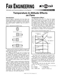
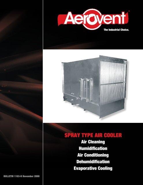
®The Industrial Choice.SPRAY TYPE AIR COOLER<strong>Air</strong> CleaningHumidification<strong>Air</strong> ConditioningDehumidificationEvaporative CoolingBULLETIN 1103-B November 2000
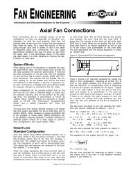
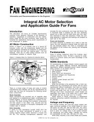
<strong>Spray</strong> <strong>Type</strong> <strong>Air</strong> CoolerThe spray type air cooler is an enclosure containing three elements:a spray bank consisting of nozzles for producing a finespray from water supplied to them under pressure, an eliminatorfor removing water from air passing through the air cooler,and a basin for collecting the used water to be returned to thepump for recirculation.This single device is capable of performing several functionsdepending upon how the thermodynamic condition ofthe water is controlled. If we recirculate water and pass outsideair through the air cooler we have an evaporative cooler.The recirculated water will stabilize at near the wet bulb temperature,and the temperature difference between the enteringand leaving air will approach the wet bulb depression. Theevaporative cooler may be used effectively in almost all areasof the United States for spot cooling of personnel working inhigh-heat producing operations, for general cooling of wholeareas of hot operation where large air volumes can be used.This same cooler can work as a highly efficient heatabsorber when provided with chilled water from a mechanicallyrefrigerated chiller or from a well (well water temperature55°F or lower).Features• All air coolers feature two spray banks, one concurrentwith and one opposed to the air flow.• Saturation efficiency is maintained at 90% across the performancerange by varying the spray density between 6and 8 gallons per square foot per minute.• The assembly is constructed of galvanized steel as standard.A stainless steel housing and/or eliminators areavailable at additional cost.• <strong>Spray</strong> nozzles are polypropylene. Headers and risers areconstructed of Schedule 40 PVC.• <strong>Air</strong> coolers are equipped with suction screens, sump levelmonitor, bronze float valve for automatic water levelcontrol, and interior vapor-proof marine light fixturewith exterior junction box.2 <strong>Aerovent</strong> Bulletin 1103
Performance DataMODELFACE AREA(FT 2 )NOMINAL STATIC SPRAYSATURATIONPUMPCFM FACE PRESSURE VOLUME PSIEFFICIENCYHPVELOCITY LOSS GPM %AC404P 15.012000 800 0.32 105 23 3 9015000 1000 0.45 110 26 3 9017500 768 0.25 155 23 3 90AC604P 22.8 20000 877 0.32 162 25 3 9022500 987 0.41 167 27 5 9025000 730 0.25 229 23 7 1 ⁄2 90AC606P 34.2 30000 877 0.32 243 25 7 1 ⁄2 9035000 1023 0.45 250 27 7 1 ⁄2 9040000 871 0.32 326 26 7 1 ⁄2 90AC806P 45.9 45000 980 0.42 340 28 10 9050000 1089 0.52 350 29 10 9055000 899 0.33 441 26 15 90AC808P 61.2 60000 980 0.40 447 27 15 9065000 1062 0.46 459 29 15 9070000 926 0.38 544 23 15 90AC1008P 75.6 75000 992 0.45 560 24 15 9080000 1058 0.52 570 25 15 9085000 900 0.38 680 23 15 90AC1010P 94.5 90000 952 0.44 690 24 15 90100000 1058 0.53 716 25 15 90FOR EVAPORATIVE COOLING APPLICATION:Leaving Dry Bulb Temperature = Entering Dry Bulb – Saturation Efficiency x (Entering Dry Bulb – Entering Wet Bulb)CONTACT YOUR AEROVENT REPRESENTATIVE FOR SPECIAL APPLICATIONS.Design Temperature ConditionsMAX.DESIGNSTATE CITY TEMP.DB WB(°F) (°F)Alabama Birmingham 96 78Arizona Phoenix 109 76Arkansas Little Rock 99 80Fresno 102 72California Los Angeles 93 72Sacramento 101 72Colorado Denver 93 64Connecticut Hartford 86 75Delaware Wilmington 92 77FloridaJacksonville 96 79Miami 91 79Georgia Atlanta 94 77Idaho Boise 96 68Illinois Chicago 94 79Indiana Fort Wayne 92 77Iowa Davenport 94 78Kansas Wichita 101 77Kentucky Louisville 95 79Louisiana Shreveport 99 79Maine Portland 87 74MAX.DESIGNSTATE CITY TEMP.DB WB(°F) (°F)Maryland Baltimore 94 78Massachusetts Boston 91 75Michigan Detroit 91 76Minnesota Minneapolis 92 77Mississippi Meridian 97 80MissouriKansas City 99 78St. Louis 98 78MontanaBillings 94 67Helena 91 64NebraskaLincoln 99 78Omaha 94 78Nevada Las Vegas 108 71New Hampshire Concord 90 74New Jersey Newark 94 77New Mexico Albuquerque 96 66Buffalo 88 74New York New York 92 76Rochester 91 75North Carolina Asheville 89 75North Dakota Bismarck 95 73These values will be met or exceeded 1% of the summer months June through September.MAX.DESIGNSTATE CITY TEMP.DB WB(°F) (°F)OhioCincinnati 92 77Cleveland 91 76Oklahoma Tulsa 101 79Oregon Portland 90 69PennsylvaniaPhiladelphia 93 77Pittsburgh 91 74Rhode Island Providence 89 75South Carolina Charleston 94 81South Dakota Rapid City 95 71Tennessee Memphis 98 80Austin 100 78Texas Dallas 102 78Houston 97 80Utah Salt Lake City 97 66Vermont Burlington 88 74VirginiaLynchburg 93 77Richmond 95 79Washington Seattle 85 69West Virginia Parkersburg 93 77Wisconsin Milwaukee 90 76Wyoming Cheyenne 89 633 <strong>Aerovent</strong> Bulletin 1103 <strong>Aerovent</strong> Bulletin 1103 3
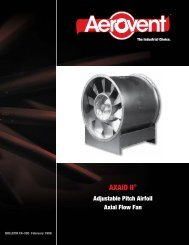
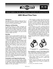
Dimensional DataApproximate Location of Pump Dischargeto Manifold Inlet. Location Varies With PumpLocation. (See Note 5)10512 GA. Galv. Construction w/Epoxy FinishAccess Door AvailableOn Either Side of Unit(21 x 27 Opening)21 1 /16BSee Note 3PVC Risers WithPolypropylene NozzlesMarine LightFixture<strong>Spray</strong>Section7 /8<strong>Air</strong>flowSuctionPipeJ8 1 /239NKOverflowDrainFast FillMake-upSupply18 1 /2M52 1 /2K10GalvanizedEliminatorsC(Inside)14 1 /211 1 /2WaterLevelASeeNote 42D(Inside)D + 1 /4(8) 7 /16 Dia. Holes in 3" Channel(8) 9 /16 Dia. Holes in 5" ChannelNOTES:1. Overflow, drain, suction, and make-up piping available on either side.2. Suction screens provided.3. (E) 7 ⁄16" diameter holes spaced at 8 5 ⁄8" C L to C L from C L (typ. each end).4. (F) 7 ⁄16" diameter holes spaced at 8 5 ⁄8" C L to C L from C L (typ. each end).5. Pump and motors are available, but not provided as standard equipment. Location is also optional.6. Lifting lugs (4) are provided (welded to basin).7. Specify location of door, pump, motor, and piping by LH or RH when facing discharge side of unit. LH shown (standard).21See Note 4See Note 312 GA.Galv. BasinSIZEGALS M/U FAST OVER APPROX.FACE DIMENSIONS (INCHES) SUCT.DRAINPER SUPPLY FILL FLOWWEIGHTAREA PIPEPIPEMIN. PIPE PIPE PIPE(FT 2 ) A B C D E F J K L M N SIZESIZE DRY WETNOM. SIZE SIZE SIZEAC404P 15.0 55 1 /2 60 3 ⁄8 39 56 3 19⁄8 7 5 ⁄32 33 19 ⁄32 12 1 /2 4 3 ⁄4 4 115 3⁄4 1 2 2 2000 48003"AC604P 22.8 75 1 /2 60 3 ⁄8 59 56 3 19⁄8 7 7 ⁄32 33 19 ⁄32 12 1 /2 4 3 ⁄4 4 175 3⁄4 1 2 2 2340 51404.1#AC606P 34.2 75 1 /2 88 3 ⁄8 59 84 3 19⁄8 9 7 ⁄32 33 19 ⁄32 12 1 /2 4 3 ⁄4 4 250 3⁄4 1 2 2 3270 7610AC806P 45.9 95 1 /2 88 3 ⁄8 79 84 3 ⁄8 9 9 3⁄4 33 1 /8 13 5 3 ⁄4 6 350 3⁄4 1 3 3 3490 7830AC808P 61.2 95 1 /2 116 3 ⁄4 79 112 3 ⁄4 13 9 3⁄4 33 1 /8 5" 13 5 3 ⁄4 6 455 3⁄4 1 3 3 4810 10550AC1008P 75.6 121 1 /2 116 3 ⁄4 105 112 3 ⁄4 13 11 3⁄4 33 1 /8 9.0# 13 5 3 ⁄4 6 585 3⁄4 1 3 3 5500 11240AC1010P 94.5 121 1 /2 144 3 ⁄4 105 140 3 ⁄4 17 11 3⁄4 33 1 /8 13 5 3 ⁄4 6 690 3⁄4 1 3 3 6670 13810Dimensions are not to be used for construction.4 <strong>Aerovent</strong> Bulletin 1103
©2004 <strong>Aerovent</strong>, Twin City Fan Companies, Ltd.Bulletin illustrations cover the general appearance of products at the time of publication andwe reserve the right to make changes in design and construction at any time without notice.5 <strong>Aerovent</strong> Bulletin 1103
PROPELLER FANS | TUBEAXIAL & VANEAXIAL FANS | CENTRIFUGAL FANS & BLOWERS | ROOF VENTILATORSINDUSTRIAL AIR HANDLERS | AIR MAKE-UP | FIBERGLASS FANS | CUSTOM FANS®AEROVENTA Twin City Fan CompanyWWW.AEROVENT.COM5959 Trenton Lane N | Minneapolis, MN 55442 | Phone: 763-551-7500 | Fax: 763-551-7501