Single Phase AC Induction Squirrel Cage Motors - Aerovent
Single Phase AC Induction Squirrel Cage Motors - Aerovent
Single Phase AC Induction Squirrel Cage Motors - Aerovent

Create successful ePaper yourself
Turn your PDF publications into a flip-book with our unique Google optimized e-Paper software.
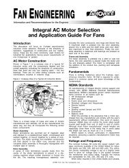
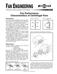
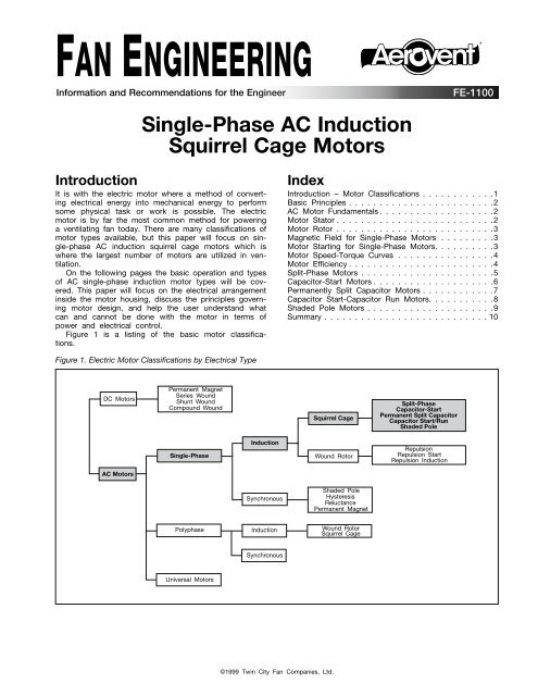
Basic PrinciplesIn order to understand how the single-phase <strong>AC</strong> inductionmotor works a basic understanding of the physicalprinciples and fundamentals governing motor design andoperation is required. We will start with the basic principleon which the induction motor is able to convertelectrical energy into mechanical energy.The basic operation of an <strong>AC</strong> induction motor isbased on two electromagnetic principles:1. Current flow in a conductor will create a magneticfield surrounding the conductor, and,2. If a conductor is moved through this magnetic field,current is induced in the conductor and it will createits own magnetic field.The fundamental single-phase <strong>AC</strong> induction motor consistsof two basic parts (see Figure 2).Figure 2. Basic Components of a <strong>Single</strong>-<strong>Phase</strong><strong>AC</strong> <strong>Induction</strong> Motor<strong>AC</strong> <strong>Induction</strong> Motor FundamentalsStatorWhenever current flows in a conductor, a magnetic fieldis built up around it (Figure 3). If the conductor isformed into a coil, the magnetic field created is similarto that of a permanent bar magnet (Figure 4). If a barof magnetic material such as iron or steel is placedwithin the coil, the magnetic field is strengthenedbecause these materials transmit magnetic flux muchmore readily than air.Figure 3. Magnetic Field Surrounding ConductorFigure 4. Magnetic Field Produced by a Simple Coilwith Permanent Magnet1. Stator. The stator is constructed of a set of stackedlaminated discs which are surrounded by a statorwinding. This winding is connected to the properpower supply (voltage, phase and frequency) andproduces a magnetic field that revolves around themotor at a speed designated “synchronous.”2. Rotor. The rotor is connected to the output shaft andconsists of a shorted aluminum winding which is castinto slots and stacked and joined at both ends of thestack with end rings. The rotor acts as a conductorwhich when placed in the magnetic field of the statorwinding creates a magnetic field of its own and interactswith the magnetic field of the stator, producingtorque.The first principle applies to the magnetic field createdby the stator and the second applies to the rotoras it rotates within the stator field.Figure 5 is a view of one half of a four pole stator.The placement of the coils resembles the relative positioningof the coil and bar of Figure 4 and the resultingmagnetic fields are also similar. By reversing the directionin which one coil is wound in the stator relative tothe adjacent coil, the direction of current flow isreversed, as illustrated in Figure 5. This reversal in thedirection of current flow also changes the magneticpolarity, creating adjoining north and south poles in thestator.Figure 5. Flux Patterns Produced in StatorBefore we cover the characteristics of the variousmotor types, it may be useful to review in detail thebasic electromagnetic principles which enable the inductionmotor to convert electrical energy into a mechanicaloutput through the motor shaft. We will start by takinga look into the two main components (stator and rotor)of single-phase <strong>AC</strong> motors. In the following section wewill discuss their construction and the fundamental principlesof their operation.2 Fan Engineering FE-1100
In the completed stator, a magnetic field is createdhaving alternating north and south poles. The number ofmagnetic poles in the stator, together with the <strong>AC</strong> linefrequency, determines the speed at which the motor willoperate.RotorIf a conductor is moved between the faces of a horseshoemagnet (Figure 6), a voltage is induced in thatconductor, and if the conductor forms part of a completedcircuit, current will flow. The action which producesthis voltage and current is the cutting of themagnetic field (called lines of magnetic flux) by the conductor.This current flow within the conductor will in turnproduce a magnetic field, as seen in Figures 3 and 6.The interaction of these two magnetic fields produces amechanical force on the wire which is the basis for theproduction of torque.Figure 6. Elements of Motor ActionV dcDirection ofOpposingForceDirectionof MotionIn an induction motor, the single conductor of theprevious example is replaced by the rotor winding. Insmall motors, this winding is normally of cast aluminumand consists of multiple conductors, or rotor bars, castinto the slots in the rotor core and joined at both endsof the stack with end rings. The resulting rotor windingcircuit is illustrated in Figure 7, and as can be seen fromthis figure, the name has been designated as “squirrelcage rotors.”Figure 7. Representation of Voltage-CurrentPaths (and Strengths) in <strong>Squirrel</strong> <strong>Cage</strong> RotorSNis passing through at that time. Because the strength ofthe stator field varies around its circumference, beingstrongest at each pole, the voltages and currentsinduced in the rotor bars will also vary around the rotor.Figure 7 illustrates the directions and magnitudes of atypical rotor bar current pattern. The magnetic field builtup around each bar reacts with the stator flux, exertinga force on each bar in the same manner as previouslydescribed in the example of the horseshoe magnet andsimple conductor. The sum total of all forces acting onall rotor bars is the output torque of the motor.Magnetic Field for <strong>Single</strong>-<strong>Phase</strong> <strong>Motors</strong>In order for the rotor to move, the stator must producea rotating magnetic field. With a single source of <strong>AC</strong>voltage connected to a single winding, this is not possible.A stationary flux field is created which pulsates instrength as the <strong>AC</strong> voltage varies, but it does not rotate.This pulsating field strength is what simulates a rotatingfield and gives the rotor its rotation. If a stationary rotoris placed in this single-phase stator field, it will notrotate, but if the rotor is spun by hand, it will pick upspeed and run. The single-phase motor will run (in eitherdirection) if started by hand, but it will not develop anystarting torque as illustrated in Figure 8.Motor Starting for <strong>Single</strong>-<strong>Phase</strong> <strong>Motors</strong>What is needed is a second (start) winding, with currentsout of phase with the original (main) winding, to producea net rotating magnetic field. The various single-phasemotor designs differ in the type of secondary (start)winding employed. These start windings, which togetherwith other components such as capacitors, relays andcentrifugal switches, make up the starting circuit, providevarying effects on motor starting and running characteristics.Figure 8. Speed-Torque Characteristics of <strong>Single</strong>-<strong>Phase</strong>,<strong>Single</strong> Main Winding Only MotorPercent Synchronous Speed100806040200 0 100 200 300 400 500Percent Full-Load TorqueAs a rotor turns, the rotor bars cut through the fluxlines of the stator magnetic field and voltages and currentsare induced in each bar. The magnitude of thevoltage and current in a given bar will depend on themagnetic density of the stator field which the rotor barTwo basic mathematical models best reveal twoimportant facts about single-phase motors:1. The performance characteristics of single-phasemotors can approach, but will not exceed that of thetwo-phase polyphase motors.2. The torque produced at a given RPM is not constant,but pulsates at twice the line frequency around amedian value. These torque pulsations are inherent to3 Fan Engineering FE-1100
all single-phase motors and can cause noise andvibration problems if not properly isolated.Motor Speed-Torque CurvesDetermining what motor is necessary for the applicationis done through examining motor speed-torque curves.There is much information on a speed-torque curve totell the end user if the motor will operate satisfactorilyfor the intended application. The speed-torque curve willallow the user to determine if the motor has enoughstarting torque to overcome friction, to accelerate theload to full running speed, and if it can handle themaximum overload expected. See Figure 9 for a typicalspeed-torque curve.Figure 9. Typical Motor Speed-Torque CurveMotor Speed in RPM or Percent Synchronous SpeedSynchronous SpeedNo Load Motor SpeedFull Load orRated Motor SpeedFull Load Operating PointApprox. Max. Torque RecommendedFor Short Time OverloadsBreakdown or Max. Torque(Developed During Acceleration)RPM Slip at Full Load orPercent Rated SlipTorqueDotted Portion of Speedvs. Torque Curve Applicableto Initial Acceleration}Full Load or Rated TorqueSpeed at WhichService Factor Load or TorqueBreakdown TorqueCusp or is DevelopedPull-up Torque or Min.Lowpoint inAccelerating Torque } AccelerationTorqueLocked Rotor or Starting TorqueThere are many torques that can be obtained from amotor’s speed-torque curve:• Locked Rotor (Starting) Torque — Motor torque at zerospeed.• Pull-Up Torque — Lowest torque value between zeroand full load speed.• Breakdown Torque — Maximum torque without motorstalling.• Full Load Torque — Torque produced by motor at fullload operating point.As we further describe the five types of single-phase<strong>AC</strong> induction motors, reference to the speed-torquecurves will be crucial to understanding each motor typeand its operating characteristics.Motor Efficiency<strong>Single</strong>-phase <strong>AC</strong> induction squirrel cage peak motorefficiencies range from as low as 30% to as high as65%, depending on the motor type and design. Motorefficiencies also depend on the actual motor load versusrated load. Refer to Figure 10.The best motor for the job is often suggested by thenature of the load. Motor efficiency usually is greatestat the full load rating and falls off rapidly for under andoverloaded conditions as can be seen in Figure 10.The misconception that a motor running well belowits maximum load rating will run cooler and more efficientlyis not true. Oversizing <strong>AC</strong> motors reduces efficiencyby a substantial amount, causing a larger part ofthe input energy to be dissipated as heat. On the otherend of the scale, overloading of motors is a much betterunderstood concept as many other signs indicate apoor motor selection (reduced speed, high ampere draw,tripped motor overloads). The amount of electrical powerwasted can be reduced by a more careful application ofa motor to the actual load. It is typically best to run an<strong>AC</strong> single-phase squirrel cage motor at no less than75% full load and no greater than 125% full load froman efficiency standpoint. Again, motor efficiency is greatestnear its full load rating.Figure 10. Motor Efficiency vs. Motor LoadEfficiency (%)70605040Permanently Split Capacitor Motor(<strong>Single</strong> <strong>Phase</strong>, 4 Pole, 3/4 HP)300 25 50 75 100 125 150 175 200Motor Load (% of Full Load)Another design criteria affecting motor efficiency isoperating voltage. <strong>Motors</strong> are generally designed tooperate at a given rated voltage, with a plus and minustolerance (10% is typical). Within the tolerance level,efficiency generally increases for higher voltages, butdecreases for lower voltages. The decrease is due togreater I 2 R losses (because of the substantial length ofwire required in the winding, this results in I 2 R lossesbecause of the principle that the wire resistance increaseswith its length). Low operating voltage also reducestorque, which decreases as the square of the voltage.Refer to Figure 11.Figure 11. Effect of Voltage on Motor EfficiencyPercent Change in Motor Efficiency (%)20151050-5-10-15EfficiencyPermanently Split Capacitor Motor(<strong>Single</strong> <strong>Phase</strong>, 4 Pole, 3/4 HP)-30-20 -15 -10 -5 0 5 10 15 20Percent Voltage Variation (%)Beyond these considerations, the motor design determinesits efficiency. There are several ways to reducepower losses in the motor. One is to reduce losses inthe core, either by adding more material to the magneticcore structure or by using a steel with improvedcore-loss properties. Another method is to increase thecross-sectional area of conductors to reduce resistance.This means that additional winding material must beadded to the stator and rotor. Another alternative is toshorten the air gap between the rotor and stator toreduce the magnetizing current required. A final method4 Fan Engineering FE-1100
used is to simply add more material to the magneticcore which will reduce the amount of current requiredto magnetize the core.Figure 12 illustrates schematically the winding arrangementof a typical distributed winding arrangement of asplit-phase motor. A split-phase motor’s components area main winding, start winding and a centrifugal switch.Figure 12. Winding Schematic for SP MotorV LI LThe main (run) winding is designed for operation from75% synchronous speed and above. The main windingdesign is such that the current lags behind the line voltagebecause the coils embedded in the steel statornaturally build up a strong magnetic field which slowsthe buildup of current in the winding. This relationshipbetween the line voltage and line current is shown inFigure 13.The start winding is not wound identically to themain, but contains fewer turns of much smaller diameterwire than that of the main winding coils. This is requiredto reduce the amount the start current lags the voltage.This can also be seen in Figure 13.When both windings are connected in parallel acrossthe line, the main and start winding currents will be outof time phase by about 30 degrees. This forms a sortof imitation of a weak rotating flux field which is sufficientto provide a moderate amount of torque at standstilland start the motor.Figure 13. <strong>Phase</strong> Relationships (SP Motor)VI MMainWindingI MStartWindingSplit-<strong>Phase</strong> <strong>Motors</strong> (SP)I SSmallConductorVolumeSwitchThe total current that this motor draws while startingis the vector sum of the main and start winding currents.Because of the small angle between these two, the linecurrent during starting (inrush current) of split-phasemotors is quite high. Also the small diameter wire in thestart winding carries a high current density, so that itheats up very rapidly. A centrifugal switch mechanism(or relay) must be provided to disconnect the start windingfrom the circuit once the motor has reached anadequate speed to allow running on the main windingonly. Figure 14 illustrates the speed-torque relationshipof a typical split phase motor on both the running andstarting connection. Table 1 summarizes the split-phasemotor characteristics.Figure 14. General Performance Characteristic(SP Motor)Percent Synchronous Speed10080604020RunWindingStartWinding0 0 100 200 300 400 500Percent Full-Load TorqueCHAR<strong>AC</strong>TERISTICNOTESPeak Efficiency 50 to 60%Power Factor 60 to 70%Starting Torque100% Full Load TorqueNoise & Vibration120 Hz Torque PulsationsComponentsContains Centrifugal SwitchOtherHigh Inrush Starting CurrentCostModerateI S30°V=~I SI MI L5 Fan Engineering FE-1100
Capacitor-Start <strong>Motors</strong> (CSIR)The new result is a time phase shift closer to 90V LI SV LTable 1. Summary of Split-<strong>Phase</strong> Motor CharacteristicsPeak Efficiency 50 to 60%I STable 2. Summary of Capacitor-Start Motor CharacteristicsFigure 15 illustrates schematically the winding arrangementof a typical distributed winding arrangement of acapacitor-start motor. It should be noted that the capacitor-startmotor utilizes the same winding arrangement asthe split-phase motor, but adds a capacitor in serieswith the start winding. The effect of this capacitor isshown in Figure 16. The main (run) winding currentremains the same as in the split-phase case, but thestart winding current is very much different. With thecapacitor in the circuit, the starting current now leadsthe line voltage, rather than lagging as does the mainwinding. The start winding is also different, containingslightly more turns in its coils than the main winding andutilizing wire diameters only slightly smaller than thosedegrees than with the split-phase motor. A strongerrotating field is therefore created and starting torque ishigher than with the split-phase design. Also the vectorsum of the main and start winding currents is lower,resulting in a reduction in the inrush current as comparedto the split-phase design. Refer to Figure 16.The starting and running speed-torque characteristicof a capacitor-start motor is illustrated in Figure 17.Again, a centrifugal switch and mechanism (or relay)must be used to protect the start winding and capacitorfrom overheating. When the capacitor-start motor is runningnear full load RPM, its performance is identical tothat of the split-phase motor. Table 2 summarizes thecapacitor-start motor characteristics.of the main.Figure 17. General Performance CharacteristicFigure 15. Winding Schematic for CSIR Motor(CSIR Motor)100Main80V LWindingSwitchStartRunShort-TimeWinding60 WindingRatedI M StartCapacitorI Winding40LI S200 0 100 200 300 400Figure 16. <strong>Phase</strong> Relationships (CSIR Motor)Percent Full-Load Torque500I MCHAR<strong>AC</strong>TERISTICNOTESPower Factor 60 to 70%Starting Torque Up to 300% Full Load Torque(Intermittent Duty)II LNoise & VibrationComponents120 Hz Torque PulsationsContains Centrifugal Switch & CapacitorMOtherCapacitor Controls Inrush Starting Current(Lower Than Split-<strong>Phase</strong> Type)CostSlightly Higher Than Split-<strong>Phase</strong> TypePercent Synchronous Speed6 Fan Engineering FE-1100
Permanently Split Capacitor <strong>Motors</strong> (PSC)Figure 18 illustrates schematically the winding arrangementof a typical distributed winding arrangement of apermanently split capacitor motor. The windings of thePSC motor are arranged like those of the split-phaseand capacitor-start designs, but a capacitor capable ofrunning continuously replaces the intermittent dutycapacitor of the capacitor-start motor and the centrifugalswitch of both the split-phase and capacitor-startmotors. The main winding remains similar to the previousdesigns, current lags the line voltage (refer to Figure19).Figure 18. Winding Schematic for PSC MotorVLILIMMainWindingStartWindingISContinuousRatedCapacitorHowever, the real strength of the permanently splitcapacitor design is derived from the fact that the startwinding and capacitor remain in the circuit at all timesand produce an approximation of two-phase operationat the rated load point. This results in better efficiency,better power factor, and lower 120 Hz torque pulsationsthan in equivalent capacitor-start and split-phasedesigns.Figure 20 illustrates a typical speed torque curve fora permanently split capacitor motor. Different startingand running characteristics can be achieved by varyingthe rotor resistance. In addition, by adding extra mainwindings in series with the original main windings, PSCmotors can be designed to operate at different speedsdepending on the number of extra main windings energized.It should also be noted that for a given full loadtorque, less breakdown torque and therefore a smallermotor is required with a permanently split capacitordesign than with the other previously discussed designs.Table 3 summarizes the characteristics of the permanentlysplit capacitor design.Figure 20. General Performance Characteristic(PSC Motor)The start winding of a PSC motor is somewhat differentthan in the capacitor-start design. Because thecapacitor for a PSC motor usually has a small rating, itis necessary to boost the capacitor voltage by addingconsiderably more turns to its coils than are in the mainwinding coils. Start winding wire size remains somewhatsmaller than that of the main winding. The smallermicrofarad rating of the capacitor produces more of aleading phase shift and less total start winding current,so starting torques will be considerably lower than withthe capacitor-start design. Refer again to Figure 19.1008060402000I I S MI SFigure 19. <strong>Phase</strong> Relationships (PSC Motor)Percent Synchronous SpeedLowResistanceRotorHighResistanceRotor100 200 300 400 500Percent Full-Load TorqueTable 3. Summary Permanently Split CapacitorMotor CharacteristicsI MI LV LVCHAR<strong>AC</strong>TERISTICNOTESPeak Efficiency 55 to 65%Power Factor 80 to 100%Starting Torque 50 to 80% Full Load TorqueNoise & Vibration 120 Hz Torque Pulsations ReducedComponents Contains Capacitor (Continuous Duty)OtherCan be used with speed control devices (notpossible with SP & CSIR types)CostSmallest motor for given output7 Fan Engineering FE-1100
Capacitor Start-Capacitor Run <strong>Motors</strong> (CSCR)Figure 21 illustrates schematically the winding arrangementof a typical distributed winding arrangement of acapacitor start-capacitor run motor. These motors havea run capacitor and an auxiliary winding permanentlyconnected in parallel with the main winding. In addition,a starting capacitor and a centrifugal switch are also inparallel with the run capacitor. The switch disconnectsas the motor accelerates. It should be noted that thecapacitor start-capacitor run motor utilizes the samewinding arrangement as the permanently split capacitormotor when running a full load speed and the samewinding arrangement as a capacitor-start motor duringstartup.Figure 22 illustrates a typical speed torque curve fora capacitor start-capacitor run motor. With the advantageof combining both the PSC and capacitor-startdesigns these motors have been extended up to ratingsas high as 20 HP, far beyond what the other singlephasemotor types are capable.Table 4 summarizes the characteristics of the capacitorstart-capacitor run motor.Figure 22. General Performance Characteristic(CSCR Motor)100Figure 21. Winding Schematic for CSCR MotorAuxiliaryWindingMainWindingRotorStartCapacitorRunCapacitorPercent Synchronous Speed80604020RunWindingStartWindingThe advantage of the capacitor start-capacitor rundesign is derived from the fact that the start windingand capacitor remain in the circuit at all times (similarto PSC type motor) and produce an approximation oftwo-phase operation at the rated load point, plus withan additional capacitor in series with the start windingcircuit (similar to the capacitor-start type motor), thestarting current now leads the line voltage, rather thanlagging as does the main winding, dramatically increasingstarting torque. Capacitor start-capacitor run motorsfeature a low running current due to an improved powerfactor caused by the run capacitor.This results in better efficiency, better power factor,increased starting torque and lower 120 Hz torque pulsationsthan in equivalent capacitor-start and split-phasedesigns. The capacitor start-capacitor run motor is basicallya combination of the capacitor-start and PSCmotor types and is the best of the single-phasemotors.0 0 100 200 300 400 500Percent Full-Load TorqueTable 4. Summary Capacitor Start-Capacitor Run MotorCharacteristicsCHAR<strong>AC</strong>TERISTICNOTESPeak Efficiency 55 to 65%Power Factor 80 to 100%Starting Torque Up to 300% Full Load TorqueNoise & Vibration 120 Hz Torque Pulsations ReducedComponents Contains Centrifugal Switch & Capacitor(Intermittent Duty).Contains 2nd Capacitor (Continuous Duty).OtherCapacitor controls inrush starting current & runcapacitor simulates 2-phase operation.CostThe best of the single-phase motor types.Exceptionally quiet.Most expensive motor design type.8 Fan Engineering FE-1100
Shaded Pole <strong>Motors</strong>The shaded pole motor differs widely from the othersingle-phase motors which have been discussed. All ofthe other designs contain a main and start winding, differingonly in details of the starting method and correspondingstarting circuitry.The shaded pole motor is the most simply constructedand therefore the least expensive of the single-phasedesigns. It consists of a run winding only plus shadingcoils which take the place of the conventional startwinding. Figure 23 illustrates the construction of a typicalshaded pole motor. The stator is of salient poleconstruction, having one large coil per pole wounddirectly in a single large slot. The shading coils are shortcircuited copper straps which are wrapped around onepole tip of each pole.point “b”. As slight as this shift is, it is sufficient togenerate torque and start the motor.The single coil winding is the crudest possibleapproximation of a rotating magnetic field. Therefore, theshaded pole motor efficiency suffers greatly due to thepresence of winding harmonic content, particularly thethird harmonic which produces a dip in the speed torquecurve at approximately 1/3 synchronous speed (refer toFigure 24). In addition there are losses in the shadingcoils. These factors combine to make the shaded polethe least efficient and noisiest of the single-phasedesigns. It is used mostly in air moving applicationswhere its low starting torque and the third harmonic dipcan be tolerated. Extra main windings can be added toprovide additional speeds in a manner similar to thatused on permanently split capacitor motors. Table 5summarizes the characteristics of a shaded polemotor.Figure 24. General Performance Characteristic(Shaded Pole Motor)100Figure 23. Shaded Pole Motor ConstructionThe shaded pole motor produces a very crude approximationof a rotating stator field through magnetic couplingwhich occurs between the shading coils and thestator winding. The placement and resistance of theshading coil is chosen so that, as the stator magneticfield increases from zero at the beginning of the <strong>AC</strong>cycle to some positive value, current is induced in theshading coil. As previously noted, this current will createits own magnetic field which opposes the original field.The net effect is that the shaded portion of the pole isweakened and the magnetic center of the entire pole islocated at point “a”. As the flux magnitude becomesnearly constant across the entire pole tip at the top ofthe positive half cycle, the effect of the shading pole isnegligible and the magnetic center of the pole shifts toPercent Synchronous Speed80604020ThirdHarmonicDip0 0 100 200 300 400 500Percent Full-Load TorqueTable 5. Summary Shaded Pole Motor CharacteristicsCHAR<strong>AC</strong>TERISTICNOTESPeak Efficiency 20 to 40%Power Factor 50 to 60%Starting Torque 40 to 50% full load torque plusthird harmonic dipNoise & Vibration 120 Hz torque pulsations pluswinding harmonicsComponents No additional components neededOtherCan be used with speed control devices (notpossible with SP & CSIR types)CostCheapest of all single-phase motors9 Fan Engineering FE-1100
<strong>Single</strong>-phase <strong>AC</strong> motors are not all equal. There are fivebasic types, all with different operating characteristicsand capabilities. As it has been shown, the differencesbetween each motor type are great enough that it isimportant for the user to understand each motor type,where it makes sense to apply them and how to applythem.What does knowing the previous technical informationon these five types of motors have to do with fans?The answer is simply this: almost every commercial fanis powered by an electric motor and other than the fanwheel it is by far the most important component of afan. The motor is the most likely component to fail in afan and a large percentage of fan motor failures can beattributed to poor selection and application of themotor.SummarySpeed control capability is also becoming more commonplacetoday (especially on direct drive fans) andapplying today’s speed controllers to any single-phase<strong>AC</strong> motor can prove disastrous. It is important to understandthat there are only two types of single-phase <strong>AC</strong>squirrel cage motor types that are suited for speedcontrol applications.Understanding the starting characteristics of eachmotor type is another area of importance for the motorapplication to a particular fan. All five motor types havedistinct starting characteristics that need to be properlymatched with the fan starting characteristics.The table below can be used as a quick referenceto the five motor types along with typical (acceptable)fan applications for each motor type.Table 6. Summary of Five <strong>Single</strong>-<strong>Phase</strong> Motor TypesMOTOR TYPE SPLIT-PHASE CAP<strong>AC</strong>ITOR-STARTDESCRIPTIONStart winding connectedin parallelwith main winding,connection controlledby centrifugal switchor relay.Identical to the splitphasedesign exceptincludes the additionof a capacitor inseries with the startwinding circuit.PERMANENTLY SPLITCAP<strong>AC</strong>ITORStart winding permanentlyconnected inparallel to main windingwith a continuousduty capacitor in thecircuit at all times.CAP<strong>AC</strong>ITOR START-CAP<strong>AC</strong>ITOR RUNCombination ofcapacitor-start andPSC type motor. Startwinding permanentlyconnected in parallelto main winding witha continuous dutycapacitor in the circuitat all times andcapacitor in serieswith the start windingcircuit.SHADED POLE<strong>Single</strong> main windingwith shadingcoils for providingstarting torque.HP RANGE 1/6 to 1 1/4 to 2 1/100 to 1 3/4 to 20 1/1000 to 1/4TYPICAL RATED 860, 1140, 1725,3450EFFICIENCYRANGE860, 1140, 1725,34501050, 1625, 3250 1725, 3450 1050, 1550, 310050 to 60% 50 to 60% 55 to 65% 55 to 65% 20 to 40%POWER F<strong>AC</strong>TOR 60 to 70% 60 to 70% 80 to 100% 80 to 100% 50 to 60%STARTINGTORQUE 100% Up to 300% 50 to 80% Up to 300% 40 to 50%TYPICALSuitable for frequentstarting of fans inboth direct and beltdriven units.All-purpose motor forhigh starting torque,low starting currentused in both directand belt driven units.Intended for directdrive models andapplications requiringspeed control.All-purpose motor forhigh starting torque,low starting currentused mainly in largerbelt driven units.Suitable for directdrive low powerfans and multispeedapplications.ADVANTAGESa. Good startingtorque.b. Medium efficiency.a. High startingtorque.b. Lower startingcurrent than splitphase design.a. High runningefficiency.b. Capable of multispeedoperation.c. Can be used withspeed controldevices (i.e., triacs).d. Quietest of allsmall inductionmotors.a. High startingtorque.b. Lower startingcurrent than splitphasedesign.c. Available in largerHP sizes thancapacitor-start orPSC motor types.d. High runningefficiency.a. Inexpensive tomanufacture.b. Multi-speedoperation.c. Compact.DISADVANTAGESa. Not suited forhigh startingtorque loads.b. Not applicable forspeed control.c. High starting currenta. More expensivethan split-phasedesign.b. Not applicable forspeed control.a. Low startingtorque.b. Speed varies moreunder load.a. Most expensivesingle-phase motortype.b. Not applicable forspeed control.a. Low efficiency.b. Low startingtorque.10 Fan Engineering FE-1100
®<strong>Aerovent</strong> | www.aerovent.com5959 Trenton Lane N | Minneapolis, MN 55442 | Phone: 763-551-7500 | Fax: 763-551-7501