Axial Fan Connections - FE-2800 - Aerovent
Axial Fan Connections - FE-2800 - Aerovent
Axial Fan Connections - FE-2800 - Aerovent

You also want an ePaper? Increase the reach of your titles
YUMPU automatically turns print PDFs into web optimized ePapers that Google loves.
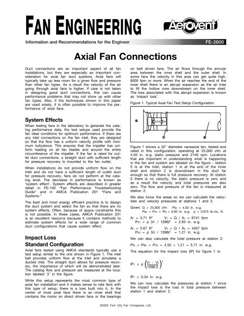
FAN ENGINEERING®Information and Recommendations for the Engineer<strong>FE</strong>-<strong>2800</strong><strong>Axial</strong> <strong>Fan</strong> <strong>Connections</strong>Duct connections are an important aspect of all faninstallations, but they are especially an important considerationfor axial fan duct systems. <strong>Axial</strong> fans willtypically take up less room for a given flow and pressurethan other fan types. As a result the velocity of the airgoing through axial fans is higher. If care is not takenin designing good duct connections, this can causeperformance problems that may not show up with otherfan types. Also, if the techniques shown in this paperare used wisely, it is often possible to improve the performanceof axial fans.System EffectsWhen testing fans in the laboratory to generate the catalogperformance data, the test setups used provide thefan ideal conditions for optimum performance. If there areany inlet connections on the fan inlet, they are designedso that the flow has a uniform velocity profile with minimumturbulence. This ensures that the impeller has uniformloading on all fan blades and around the entirecircumference of the impeller. If the fan is rated for outletduct connections, a straight duct with sufficient lengthfor pressure recovery is mounted to the fan outlet.When installations do not provide uniform flow on theinlet and do not have a sufficient length of outlet ductfor pressure recovery, fans do not perform at the cataloglevel. The decrease in performance is known as‘system effect’. System effects are described in greaterdetail in <strong>FE</strong>-100 “<strong>Fan</strong> Performance TroubleshootingGuide” and in AMCA Publication 201 “<strong>Fan</strong>s andSystems.”The best and most energy efficient practice is to designthe duct system and select the fan so that there are nosystem effects. Often, because of space constraints thisis not possible. In these cases, AMCA Publication 201is an excellent resource because it contains methods toestimate system effects for a wide range of commonduct configurations that cause system effect.Impact LossStandard Configuration<strong>Axial</strong> fans tested using AMCA standards typically use atest setup similar to the one shown in Figure 1. The inletbell provides uniform flow at the inlet and simulates aducted inlet. The straight duct allows for pressure recovery,the importance of which will be demonstrated later.The catalog flow and pressure are measured at the locationlabeled ‘2’ in the figure.While this setup represents the most common type ofaxial fan installation and it makes sense to rate fans withthis type of setup, there is a loss built into it. In thecenter of most axial fans there is an inner shell thatcontains the motor on direct driven fans or the bearingson belt driven fans. The air flows through the annulararea between the inner shell and the outer shell. Insome fans the velocity in this area can get quite high,8000 fpm or more. When the air reaches the end of theinner shell there is an abrupt expansion as the air triesto fill the hollow core downstream on the inner shell.The loss associated with this abrupt expansion is knownas ‘impact loss’.Figure 1. Typical <strong>Axial</strong> <strong>Fan</strong> Test Setup ConfigurationFigure 1 shows a 32" diameter vaneaxial fan, tested andrated in this configuration, operating at 25,000 cfm at4.50 in. w.g. static pressure and 2140 rpm. Locationsthat are important in understanding what is happeningin the fan and system are labeled on the figure - station0 is at the inlet, station 1 is at the end of the innershell and station 2 is downstream in the duct farenough so that there is full pressure recovery. At station0 there is no velocity, the static pressure is zero andas a result the velocity and total pressures are alsozero. The flow and pressure of the fan is measured atstation 2.We also know the areas so we can calculate the velocitiesand velocity pressures at stations 1 and 2.Given: Q = 25,000 cfm Ps2 = 4.50 in. w.g.Ps0 = Pv0 = Pt0 = 0.00 in. w.g. ρ = 0.075 lb./cu. ft.A1 = 3.71 ft 2 V1 = Q / A1 = 6741 fpmPv1 = ρ (V1 / 1096) 2 = 2.83 in. w.g.A2 = 5.67 ft 2 V2 = Q / A2 = 4407 fpmPv2 = ρ (V2 / 1096) 2 = 1.21 in. w.g.We can also calculate the total pressure at station 2:Pt2 = Ps2 + Pv2 = 4.50 + 1.21 = 5.71 in. w.g.The equation for the impact loss (IP) for figure 1 is:V1 - V2)2IP1 = ρ( 1096.2IP1 = 0.34 in. w.g.We can now calculate the pressures at station 1 sincethe impact loss is the loss in total pressure betweenstation 1 and station 2.©2003 Twin City <strong>Fan</strong> Companies, Ltd.
Pt1 = Pt2 + IP1 = 5.71 + 0.34 = 6.05 in. w.g.Ps1 = Pt1 – Pv1 = 3.22 in. w.g.Figure 3. <strong>Axial</strong> <strong>Fan</strong> Connected to Large Outlet Plenumor No Outlet Duct<strong>Fan</strong> Connected to Large Outlet DuctFigure 2 shows the same fan as Figure 1 only this timeit is connected to a 42" diameter duct. This makes theexpansion even more abrupt, since the air not only hasto fill the hollow core but needs to expand outward aswell.Figure 2. <strong>Axial</strong> <strong>Fan</strong> Connected to Large Outlet DuctThe flow and fan speed is the same as Figure 1, sothe pressures at stations 0 and 1 remain the same.Because the area at station 3 in Figure 2 is greater thanthe area at station 2 in Figure 1, more of the velocitypressure at station 1 is converted to static pressure, butthere is also more impact loss.For this example,A3 = 9.62 ft 2 V3 = Q / A3 = 2598 fpmPv3 = ρ (V3 / 1096) 2 = 0.42 in. w.g.The equation for impact loss (IP) for Figure 2 is:V1IP2 = ρ- V3)2( 1096.2IP2 = 1.07 in. w.g.Calculating the pressures at point 3:Pt3 = Pt1 - IP2 = 6.05 – 1.07 = 4.98 in. w.g.Ps3 = Pt3 – Pv3 = 4.56 in. w.g.Comparing Figure 2 with Figure 1, we see that in Figure2 we slow the air down to a lower velocity, thereforeconverting more of the velocity pressure at station 1 intostatic pressure. This results in the static pressure downstreamon the fan being higher in Figure 2 than in Figure1. But because this greater expansion occurs abruptly,overall more energy is lost in the airstream and the totalpressure downstream is less in Figure 2 than in Figure1.<strong>Fan</strong> Connected to Large OutletPlenum or No Outlet DuctFigure 3 takes Figure 2 to an extreme, to the pointwhere the velocity downstream of the fan is so low thatfor all practical purposes it is zero.V5 = 0 fpm Pv5 = 0.00 in. w.g.For Figure 3 the impact loss is:IP3 = ρ( V1 )21096.2IP3 = 2.83 in. w.g.Pt5 = Pt1 - IP3 = 6.05 – 2.83 = 3.22 in. w.g.Ps5 = Pt5 – Pv5 = 3.22 in. w.g.In this case the expansion is so abrupt that all of thevelocity pressure at station 1 is lost - none of it isconverted to static pressure. As a result both the staticpressure and total pressure downstream of the fan ismuch less than Figure 1.Note that pressure is directly related to energy and theimpact loss represents wasted energy. In this example,with a loss of 2.83 in. w.g. and 25,000 cfm, 11 hp iswasted. This example demonstrates how important it isto have ductwork downstream of axial fans.Figure 4. <strong>Axial</strong> <strong>Fan</strong> Connected to Ducted Outlet Cone<strong>Fan</strong> Connected to Ducted OutletConeFigure 4 shows a fan with an outlet cone connected tothe outlet of the fan and ductwork connected to theoutlet of the cone. In this case the impact loss due tofilling the hollow core is still present, but adding anoutlet cone minimizes the impact loss due to the outwardexpansion. In order to get benefit from the outletcone it is important to keep the taper angle shallow (15°2<strong>Fan</strong> Engineering <strong>FE</strong>-<strong>2800</strong>