Waterford Systems - Rick English - Swimming Pool Consultant
Waterford Systems - Rick English - Swimming Pool Consultant
Waterford Systems - Rick English - Swimming Pool Consultant

Create successful ePaper yourself
Turn your PDF publications into a flip-book with our unique Google optimized e-Paper software.
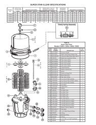
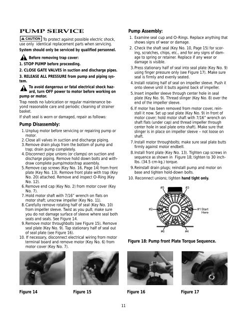
PUMP SERVICETo protect against possible electric shock,use only identical replacement parts when servicing.System should only be serviced by qualified personnel.Before removing trap cover:1. STOP PUMP before proceeding.2. CLOSE GATE VALVES in suction and discharge pipes.3. RELEASE ALL PRESSURE from pump and piping system.To avoid dangerous or fatal electrical shock hazard,turn OFF power to motor before working onpump or motor.Trap needs no lubrication or regular maintenance beyondreasonable care and periodic cleaning of strainerbasket.If shaft seal is worn or damaged, repair as follows:Pump Disassembly:1.Unplug motor before servicing or repairing pump ormotor.2.Close all valves in suction and discharge piping.3.Remove drain plugs from the bottom of pump andtrap; drain pump completely.4.Disconnect pipe unions (or clamps) on suction anddischarge piping. Remove hold down bolts and withdrawcomplete pump/motor/trap assembly.5.Remove cap screws (Key No. 16, Page 14) from frontplate (Key No. 13). Remove front plate with trap (KeyNo. 20) attached. Remove and inspect O-Ring (KeyNo. 12).6.Remove end cap (Key No. 2) from motor cover (KeyNo. 7).7.Hold motor shaft with 7/16” wrench on flats onmotor shaft; unscrew impeller (Key No. 11).8.Carefully remove rotating half of seal (Key No. 10)from impeller sleeve. Twist as you pull; make sureyou do not damage surface of sleeve where seal bothseats and seals. See Figure 14.9.Remove motor throughbolts (see Figure 15). Removeseal plate (Key No. 9). Tap stationary half of seal outof seal plate (see Figure 16).10. If necessary, disconnect electrical wiring from motorterminal board and remove motor (Key No. 6) frommotor cover (Key No. 7).Pump Assembly:1. Examine seal cup and O-Rings. Replace anything thatshows signs of wear or damage.2. Check the shaft seal (Key No. 10, Page 15) for scoring,scratches, chips, etc., and for any signs of damageto spring or retainer. Replace if any wear ordamage is visible.3.Press stationary half of seal into seal plate (Key No. 9)using finger pressure only (see Figure 17). Make sureseal is firmly and evenly seated.4.Install rotating half of seal on impeller sleeve. Push itonto sleeve until it butts against back of impeller.5.Insert impeller sleeve through center hole in sealplate (Key No. 9). Thread slinger (Key No. 8) over theend of the impeller sleeve.6.If motor has been removed from motor cover, reinstallit now. Set up seal plate (Key No. 9) in front ofmotor cover; hold motor shaft with 7/16” wrench onshaft flats (under cap) and thread impeller throughcenter hole in seal plate onto shaft). Make sure thatslinger is in place on impeller sleeve – not loose onshaft.7.Install motor throughbolts; make sure seal plate buttsfirmly against motor endbell.8.Install front plate (Key No. 13). Tighten cap screws insequence as shown in Figure 18; tighten to 30 inchlbs.(34.5 cm-kg.) torque.9.Reinstall drain plugs; reinstall pump and motor onbase and tighten hold-down bolts.10. Reconnect unions; tighten hand tight only.#2#5 #3#6#4#1 StartHereFigure 18: Pump front Plate Torque Sequence.Figure 14 Figure 15 Figure 16 Figure 1711