Jandy CL series cartridge filter - Inyo Swimming Pool Products
Jandy CL series cartridge filter - Inyo Swimming Pool Products
Jandy CL series cartridge filter - Inyo Swimming Pool Products

Create successful ePaper yourself
Turn your PDF publications into a flip-book with our unique Google optimized e-Paper software.
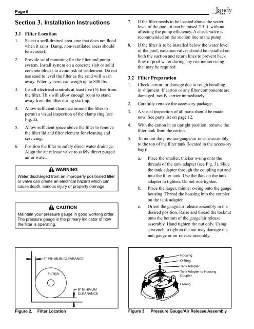
Page 6Section 3. Installation Instructions3.1 Filter Location1. Select a well-drained area, one that does not floodwhen it rains. Damp, non-ventilated areas shouldbe avoided.2. Provide solid mounting for the <strong>filter</strong> and pumpsystem. Install system on a concrete slab or solidconcrete blocks to avoid risk of settlement. Do notuse sand to level the <strong>filter</strong> as the sand will washaway. Filter systems can weigh up to 800 lbs.3. Install electrical controls at least five (5) feet fromthe <strong>filter</strong>. This will allow enough room to standaway from the <strong>filter</strong> during start-up.4. Allow sufficient clearance around the <strong>filter</strong> topermit a visual inspection of the clamp ring (seeFig. 2).5. Allow sufficient space above the <strong>filter</strong> to removethe <strong>filter</strong> lid and <strong>filter</strong> element for cleaning andservicing.6. Position the <strong>filter</strong> to safely direct water drainage.Align the air release valve to safely direct purgedair or water.WARNINGWater discharged from an improperly positioned fi lteror valve can create an electrical hazard which cancause death, serious injury or property damage.CAUTIONMaintain your pressure gauge in good work ing order.The pressure gauge is the primary indicator of howthe fi lter is operating.7. If the <strong>filter</strong> needs to be located above the waterlevel of the pool, it can be raised 2.5 ft. withoutaffecting the pump efficiency. A check valve isrecommended on the suction line to the pump.8. If the <strong>filter</strong> is to be installed below the water levelof the pool, isolation valves should be installed onboth the suction and return lines to prevent backflow of pool water during any routine servicingthat may be required.3.2 Filter Preparation1. Check carton for damage due to rough handlingin shipment. If carton or any <strong>filter</strong> components aredamaged, notify carrier immediately.2. Carefully remove the accessory package.3. A visual inspection of all parts should be madenow. See parts list on page 12.4. With the carton in an upright position, remove the<strong>filter</strong> tank from the carton.5. To mount the pressure gauge/air release assemblyto the top of the <strong>filter</strong> tank (located in the accessorybag):a. Place the smaller, thicker o-ring onto thethreads of the tank adapter (see Fig. 3). Slidethe tank adapter through the coupling nut andinto the <strong>filter</strong> tank. Use the flats on the tankadapter to tighten. Do not overtighten.b. Place the larger, thinner o-ring onto the gaugehousing. Thread the housing into the coupleron the tank adapter.c. Orient the gauge/air release assembly in thedesired position. Raise and thread the locknutonto the bottom of the gauge/air releaseassembly. Hand tighten the nut only. Usinga wrench to tighten the nut may damage thenut, gauge or air release assembly.6" MINIMUM <strong>CL</strong>EARANCEFILTER6" MINIMUM<strong>CL</strong>EARANCEHousingO-RingTank AdapterTank Adapter to HousingCouplerO-RingFigure 2.Filter LocationFigure 3.Pressure Gauge/Air Release Assembly