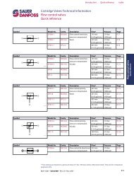
Cartridge Valves Technical Information Introduction ... - Sauer-Danfoss
Cartridge Valves Technical Information Introduction ... - Sauer-Danfoss
Cartridge Valves Technical Information Introduction ... - Sauer-Danfoss

Create successful ePaper yourself
Turn your PDF publications into a flip-book with our unique Google optimized e-Paper software.
<strong>Cartridge</strong> <strong>Valves</strong> <strong>Technical</strong> <strong>Information</strong><br />
<strong>Introduction</strong><br />
Contents<br />
1 • • • • • • • • • • • • • • • • • • • • • • • • • • • • • • • • • • • • • <strong>Introduction</strong><br />
2 • • • • • • • • • • • • • • • • • • • • • • • • • • • • • • • • • • • • • Check valves<br />
3 • • • • • • • • • • • • • • • • • • • • • • • • • • • • • • • • • • • • Shuttle valves<br />
4 • • • • • • • • • • • • • • • • • • • • • • • • • • • • • • • • • • • • • Relief valves<br />
5 • • • • • • • • • • • • • • • • • • • • • • • • • • • Pressure reducing valves<br />
6 • • • • • • • • • • • • • • • • • • • • • • • • • • • • • • • • • • Sequence valves<br />
7 • • • • • • • • • • • • • • • • • • • • • • • • • • • • • • • Flow control valves<br />
8 • • • • • • • • • • • • • • • • • • • • • • • • • Pilot operated check valves<br />
9 • • • • • • • • • • • • • • • • • • • • • • • • • • • • Counterbalance valves<br />
10 • • • • • • • • • • • • • • • • • • • • • • • • • • • • • • • • • Solenoid valves<br />
11 • • • • • • • • • • • • • • • • • • • • • • • • • • • • • • Proportional valves<br />
12 • • • • • • • • • • • • • • • • • • • • • • • • • • • • • • • • • • • Needle valves<br />
13 • • • • • • • • • • • • • • • • • • • • • • • • • Directional control valves<br />
14 • • • • • • • • • • • • • • • • • • • • • • • • • • • • • • • • • • Logic elements<br />
15 • • • • • • • • • • • • • • • • • • • • • • • • • • • • • • • • • Spreader valves<br />
16 • • • • • • • • • • • • • • • • • • • • • • • • • • • • • Motor mount valves<br />
17 • • • • • • • • • • • • • • • • • • • • • D03 Directional control valves<br />
18 • • • • • • • • • • • • • • • • • • • • • D05 Directional control valves<br />
19 • • • • • • • • • • • • • • • • • • • • • • • • • • • • • • • • • • • • • Accessories<br />
20 • • • • • • • • • • • • • • • • • • • • • • • • • • • • • • • • • • • • • • • • Cavities<br />
21 • • • • • • • • • • • • • • • • • • • • • • • • • • • • • • • • • • • • • • Housings<br />
22 • • • • • • • • • • • • • • • • • • • • • • • • • • • • • • • • • • • • • • • • • • Coils<br />
23 • • • • • • • • • • • • • • • • • • • • • • • • • • • • • • • Cross reference list<br />
24 • • • • • • • • • • • • • • • • • • • • • • • • • • • • • • • • • • • • • • • • • • Index<br />
BLN 10201 • 520L0588 • Rev. CA • Nov 2007<br />
Index<br />
Section<br />
Section<br />
Section<br />
Section<br />
Section<br />
1.1<br />
1<br />
6<br />
11<br />
16<br />
21<br />
2<br />
7<br />
12<br />
17<br />
22<br />
3<br />
8<br />
13<br />
18<br />
23<br />
4<br />
9<br />
14<br />
19<br />
24<br />
5<br />
10<br />
15<br />
20
<strong>Introduction</strong><br />
CARTRIDGE VALVE<br />
INTRODUCTION<br />
1.2<br />
<strong>Cartridge</strong> <strong>Valves</strong> <strong>Technical</strong> <strong>Information</strong><br />
<strong>Introduction</strong><br />
<strong>Cartridge</strong> valves<br />
<strong>Cartridge</strong> valves are compact and economical components that can be used for<br />
directional, pressure, or flow control in systems from 0.4 L/min [0.1 US gal/min] up to<br />
400 l/min [100 gpm], and for pressures up to 350 bar [5000 psi]. By combining standard<br />
cartridge valves almost any hydraulic circuit can be easily created. Using cartridge<br />
valves in a custom manifold, a designer can create a hydraulic integrated circuit (HIC)<br />
that provides a compact package for hydraulic control with reduced plumbing, easier<br />
installation, easier service, and fewer leak points than traditional hydraulic systems.<br />
Each valve has several key ratings, specifications, and settings:<br />
• Each <strong>Sauer</strong>-<strong>Danfoss</strong> cartridge valve fits a <strong>Sauer</strong>-<strong>Danfoss</strong> standard cavity. These<br />
cavities are designed around SAE or metric standard o-ring straight thread ports.<br />
In many cases these cavities are interchangeable with cavities used by other<br />
manufacturers. See catalog sheets for details.<br />
BLN 10201 • 520L0588 • Rev. CA • Nov 2007<br />
Index<br />
The National Fluid Power Association (NFPA) and International Standards<br />
Organization (ISO) are developing a standard, NFPA T3.5.31M-19XX, that will define<br />
an industry-wide set of standard cavities. <strong>Sauer</strong>-<strong>Danfoss</strong> will manufacture cartridge<br />
valves for NFPA cavities upon formal approval of the standard.<br />
• The pressure rating is based on NFPA fatigue test standards and a burst test at least<br />
3:1 safety factor.<br />
• The flow rating is based on the flow at a pressure drop of 7 bar [100 psi] for<br />
directional valves or a pressure rise or drop of 7 bar [100 psi] for pressure relief and<br />
reducing valves, with 32 mm 2 /s (cSt) [151 SUS] fluid. Note that for many valves this<br />
flow can be exceeded if the penalties of higher pressure drop and the associated<br />
heat generation are acceptable. The exceptions to this are solenoid-operated spooltype<br />
directional valves and proportional flow control valves where the flow ratings<br />
indicate a performance limit.<br />
• The solenoid voltage is a nominal value. All solenoid valves are designed to operate<br />
at 85% of nominal voltage with full rated flow and pressure and at an ambient<br />
temperature of 60 °C [140 °F].<br />
• Pressure settings for check, relief, reducing, sequence, and motion control valves,<br />
commonly referred to as the crack pressure, are set at a flow rate of 0.95 L/min<br />
[0.25 gpm] through the valve.<br />
• Leakage is generally measured at rated pressure limits or in the case of relief and<br />
motion control valves at 70-80% of crack pressure setting, with 32 mm 2 /s (cSt) [151<br />
SUS] fluid. See individual catalog sheets for details.<br />
• Temperature ratings vary by model and options. Seal materials provide ranges<br />
of -40 °C to 100 °C [-40° F to 212 °F] (buna-n or polyurethane) or -26 °C to 204 °C<br />
[-15 °F to 400 °F] (viton). The recommended minimum fluid viscosity is<br />
12 mm 2 /s (cSt) [66 SUS] which will override the maximum seal temperature limit<br />
for most fluids. Solenoid valves are rated for 60 °C [140 °F] maximum ambient<br />
temperature for continuous duty. Consult factory for extreme applications.
FLUIDS<br />
FILTRATION<br />
<strong>Cartridge</strong> <strong>Valves</strong> <strong>Technical</strong> <strong>Information</strong><br />
<strong>Introduction</strong><br />
Fluid and filtration recommendations<br />
BLN 10201 • 520L0588 • Rev. CA • Nov 2007<br />
Index<br />
Ratings and performance data for cartridge valves are based on operating with premium<br />
hydraulic fluids containing oxidation, rust, and foam inhibitors.<br />
These premium fluids include premium turbine oils, API CD engine oils per SAE J183,<br />
M2C33F or G automatic transmission fluids (ATF), Dexron II (ATF) meeting Allison C-3 or<br />
Caterpillar TO-2 requirements, and certain specialty agriculture tractor fluids. For further<br />
information see <strong>Sauer</strong>-<strong>Danfoss</strong> publication 520L0463, Hydraulic Fluids and Lubricants, and<br />
publication 520L0465, Biodegradable Hydraulic Fluids Applications.<br />
� CAUTION<br />
Never mix hydraulic fluids.<br />
Product performance will generally be within catalog limits with fluids meeting the<br />
recommended viscosity limits shown below.<br />
Product can be operated at viscosities outside the recommended limits, however<br />
performance may be greatly degraded. Extreme conditions must be evaluated by the<br />
user to determine acceptibility of product performance.<br />
Contact your <strong>Sauer</strong>-<strong>Danfoss</strong> representative for more information regarding fluids.<br />
It is imperative that only clean oil be used with cartridge valves to maintain valve<br />
operation and prevent premature wear. System filtration capable of controlling the fluid<br />
cleanliness to the limits shown below is required.<br />
The selection of filters depends on a number of factors including the contamination<br />
ingression rate and the desired maintenance interval. Filters are selected to meet the<br />
below requirements using rating parameters of efficiency and capacity.<br />
Filter efficiency may be measured using a Beta (β) ratio.* A filter with a β-ratio within the<br />
range of β 10 =10 is typically required.<br />
Since each system is unique, the filtration requirement for that system will be unique and<br />
must be determined by test in each case. It is essential that monitoring of prototypes<br />
and evaluation of components and performance throughout the test program be the<br />
final criteria for judging the adequacy of the filtration system. For further information<br />
see <strong>Sauer</strong>-<strong>Danfoss</strong> publication 520L467, Design Guidelines for Hydraulic Fluid Cleanliness<br />
Applications.<br />
Fluid specifications<br />
Product<br />
Cleanliness<br />
(per ISO 4406, 1999)<br />
Proportional valves 18/17/13 or better<br />
Other spool valves 20/18/14 or better<br />
All other valves 20/19/14 or better<br />
Recommended Viscosity<br />
limits<br />
mm 2 /sec (cSt) [SUS]<br />
Absolute Viscosity limits<br />
mm 2 /sec (cSt) [SUS]<br />
12-54 [66-250] 12-400 [66-1854]<br />
* Filter β x ratio is a measure of filter efficiency defined by ISO 4572. It is defined as the ratio of the number<br />
of particles greater than a given size (x) upstream of the filter to the number of particles greater than the same<br />
size downstream of the filter. The β x ratio applies to a specific particle size, measured in microns.<br />
1.3<br />
<strong>Introduction</strong>
<strong>Introduction</strong><br />
STANDARD PRESSURE<br />
SETTINGS<br />
1.4<br />
<strong>Cartridge</strong> <strong>Valves</strong> <strong>Technical</strong> <strong>Information</strong><br />
<strong>Introduction</strong><br />
Standard pressure settings and adjustment options<br />
BLN 10201 • 520L0588 • Rev. CA • Nov 2007<br />
Index<br />
The tables below detail coding for standard pressure settings. Use these tables for<br />
reference when filling in valve ordering options for valves with selectable pressure<br />
settings. Use the table on this page for valves that specify pressure in psi—typically those<br />
beginning with the letters CP. Use the table on the next page for valves that specify<br />
pressure in bar—typically those that do not begin with the letters CP.<br />
Standard settings for valves set in psi<br />
Crack Pressure<br />
(Code x 10 = psi)<br />
Crack Pressure, psi [bar]<br />
001 10 psi [0.69 bar]<br />
002 20 psi [1.38 bar]<br />
003 30 psi [2.07 bar]<br />
004 40 psi [2.76 bar]<br />
005 50 psi [3.45 bar]<br />
006 60 psi [4.14 bar]<br />
007 70 psi [4.83 bar]<br />
008 80 psi [5.52 bar]<br />
009 90 psi [6.21 bar]<br />
010 100 psi [6.9 bar]<br />
012 120 psi [8.28 bar]<br />
014 140 psi [9.66 bar]<br />
015 150 psi [10.34 bar]<br />
016 160 psi [11.0 bar]<br />
018 180 psi [12.4 bar]<br />
020 200 psi [13.8 bar]<br />
022 220 psi [15.2 bar]<br />
024 240 psi [16.6 bar]<br />
025 250 psi [17.2 bar]<br />
026 260 psi [17.9 bar]<br />
028 280 psi [19.3 bar]<br />
030 300 psi [20.7 bar]<br />
035 350 psi [24.1 bar]<br />
040 400 psi [27.6 bar]<br />
045 450 psi [31.0 bar]<br />
050 500 psi [34.5 bar]<br />
060 600 psi [41.4 bar]<br />
070 700 psi [48.3 bar]<br />
080 800 psi [55.2 bar]<br />
090 900 psi [62.1 bar]<br />
100 1000 psi [69.0 bar]<br />
110 1100 psi [75.9 bar]<br />
120 1200 psi [82.8 bar]<br />
130 1300 psi [89.7 bar]<br />
140 1400 psi [96.6 bar]<br />
Crack Pressure<br />
(Code x 10 = psi)<br />
Crack Pressure, psi [bar]<br />
150 1500 psi [103 bar]<br />
160 1600 psi [110 bar]<br />
170 1700 psi [117 bar]<br />
180 1800 psi [124 bar]<br />
190 1900 psi [131 bar]<br />
200 2000 psi [138 bar]<br />
210 2100 psi [145 bar]<br />
220 2200 psi [152 bar]<br />
230 2300 psi [159 bar]<br />
240 2400 psi [166 bar]<br />
250 2500 psi [172 bar]<br />
260 2600 psi [179 bar]<br />
270 2700 psi [186 bar]<br />
280 2800 psi [193 bar]<br />
290 2900 psi [200 bar]<br />
300 3000 psi [207 bar]<br />
320 3200 psi [221 bar]<br />
340 3400 psi [234 bar]<br />
350 3500 psi [241 bar]<br />
360 3600 psi [248 bar]<br />
380 3800 psi [262 bar]<br />
400 4000 psi [276 bar]<br />
420 4200 psi [290 bar]<br />
440 4400 psi [303 bar]<br />
460 4600 psi [317 bar]<br />
480 4800 psi [331 bar]<br />
500 5000 psi [345 bar]<br />
520 5200 psi [359 bar]<br />
540 5400 psi [372 bar]<br />
560 5600 psi [386 bar]<br />
580 5800 psi [400 bar]<br />
600 6000 psi [414 bar]<br />
XXX Pressure code stamped on<br />
valve; Pressure not set
STANDARD PRESSURE<br />
SETTINGS (continued)<br />
MECHANICAL VALVE<br />
ADJUSTMENT OPTIONS<br />
<strong>Cartridge</strong> <strong>Valves</strong> <strong>Technical</strong> <strong>Information</strong><br />
<strong>Introduction</strong><br />
Standard pressure settings and adjustment options<br />
Standard settings for valves set in bar<br />
Crack Pressure<br />
Code (bar)<br />
Crack Pressure, bar [psi]<br />
10 10 bar [145 psi]<br />
15 15 bar [218 psi]<br />
20 20 bar [290 psi]<br />
25 25 bar [363 psi]<br />
30 30 bar [435 psi]<br />
35 35 bar [508 psi]<br />
40 40 bar [580 psi]<br />
45 45 bar [653 psi]<br />
50 50 bar [725 psi]<br />
55 55 bar [798 psi]<br />
60 60 bar [870 psi]<br />
65 65 bar [943 psi]<br />
70 70 bar [1015 psi]<br />
75 75 bar [1088 psi]<br />
80 80 bar [1160 psi]<br />
85 85 bar [1233 psi]<br />
90 90 bar [1305 psi]<br />
95 95 bar [1378 psi]<br />
100 100 bar [1450 psi]<br />
105 105 bar [1523 psi]<br />
110 110 bar [1595 psi]<br />
120 120 bar [1740 psi]<br />
130 130 bar [1885 psi]<br />
Adjustment options - CP valves<br />
BLN 10201 • 520L0588 • Rev. CA • Nov 2007<br />
Crack Pressure<br />
Code (bar)<br />
Crack Pressure, bar [psi]<br />
140 140 bar [2030 psi]<br />
150 150 bar [2175 psi]<br />
160 160 bar [2320 psi]<br />
170 170 bar [2465 psi]<br />
180 180 bar [2610 psi]<br />
190 190 bar [2755 psi]<br />
200 200 bar [2900 psi]<br />
210 210 bar [3045 psi]<br />
220 220 bar [3190 psi]<br />
230 230 bar [3335 psi]<br />
240 240 bar [3480 psi]<br />
250 250 bar [3625 psi]<br />
260 260 bar [3770 psi]<br />
270 270 bar [3915 psi]<br />
280 280 bar [4060 psi]<br />
290 290 bar [4205 psi]<br />
300 300 bar [4350 psi]<br />
310 310 bar [4495 psi]<br />
320 320 bar [4640 psi]<br />
330 330 bar [4785 psi]<br />
340 340 bar [4930 psi]<br />
350 350 bar [5075 psi]<br />
XXX Pressure code stamped on<br />
valve; Pressure not set<br />
A - internal adjustment F - tamper resistant E - external adjustment<br />
K - knob adjustment<br />
Adjustment options - other valves<br />
M-handwheel<br />
EN-external<br />
E - internal<br />
P104 912E<br />
Index<br />
1.5<br />
<strong>Introduction</strong>
<strong>Introduction</strong><br />
INSPECT THE VALVE<br />
BLOCK<br />
PREPARE CARTRIDGE<br />
FOR INSERTION INTO THE<br />
BLOCK<br />
ASSEMBLY<br />
TEST<br />
CAVITY PORT<br />
IDENTIFICATION<br />
1.6<br />
<strong>Cartridge</strong> <strong>Valves</strong> <strong>Technical</strong> <strong>Information</strong><br />
<strong>Introduction</strong><br />
<strong>Cartridge</strong> valve installation procedure<br />
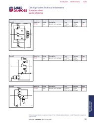
Refer to specific pages within this catalog to ensure proper port identification for<br />
cartridge functions. Inspect the valve cavity to be sure it is free of burrs, chips or other<br />
contamination.<br />
Check the cartridge to ensure it is free of external contamination, and the O-rings<br />
and back-up rings are intact. Dip the cartridge in clean oil to the top of the threads to<br />
lubricate the O-rings.<br />
Insert and screw the cartridge into its cavity by hand. It should turn easily up to the top<br />
O-ring. If it does not turn easily, the cavity has been machined improperly and the body<br />
should not be used.<br />
Torque all cartridges per specification shown on catalog sheet. Torque all coil nuts to 5-8<br />
N•m [4-6 lbf•ft] unless otherwise specified.<br />
Test the entire system to ensure that the cartridges are performing correctly and to<br />
check for leaks.<br />
Cavity 2 way Cavity 3 way<br />
Cavity 4 way<br />
BLN 10201 • 520L0588 • Rev. CA • Nov 2007<br />
4<br />
3<br />
2<br />
2<br />
1<br />
2<br />
Index<br />
P103 001 3<br />
P103 002<br />
1<br />
P103 004<br />
1
DESCRIPTION<br />
DESIGN CAPABILITIES<br />
<strong>Cartridge</strong> <strong>Valves</strong> <strong>Technical</strong> <strong>Information</strong><br />
<strong>Introduction</strong><br />
Hydraulic integrated circuits<br />
<strong>Cartridge</strong> valves can be installed in custom designed manifolds to create a Hydraulic<br />
Integrated Circuit (HIC). HICs provide many advantages over traditional hydraulic<br />
control systems:<br />
Hydraulic integrated circuits<br />
• HICs are compact packages that<br />
simplify machine plumbing.<br />
• Costs for fittings, tubes, hoses, and<br />
seals are dramatically reduced.<br />
• Installation costs are dramatically<br />
reduced.<br />
• Leak points are eliminated.<br />
• Service time and costs are<br />
dramatically reduced. Components<br />
can be replaced without disturbing<br />
machine plumbing.<br />
• HICs can be centralized on a machine<br />
or strategically located. Using a<br />
custom HIC provides the designer unlimited flexibility to optimize machines for<br />
assembly, plumbing, wiring, service, and weight distribution.<br />
<strong>Sauer</strong>-<strong>Danfoss</strong> designs and manufactures the highest quality custom HICs in the world.<br />
A custom HIC can be designed to your<br />
circuit requirements. Contact your <strong>Sauer</strong>-<br />
<strong>Danfoss</strong> representative for circuit design<br />
consultation.<br />
• Manifolds are designed using the<br />
most advanced 3-D solid modeling<br />
CAD software.<br />
BLN 10201 • 520L0588 • Rev. CA • Nov 2007<br />
State of the art CAD design<br />
Index<br />
• Advanced quality planning concepts<br />
are used throughout the design<br />
stage including product and process<br />
failure mode and effects analysis and<br />
design for manufacturability. A preproduction<br />
approval process is followed and initial sample inspection reports are<br />
used for first production pieces. Statistical process control is used to control critical<br />
features. Control plans and gauge reliability and repeatability programs are used to<br />
ensure continued quality.<br />
• Industry-leading rapid prototyping is available to support your test program<br />
requirements. Most prototype manifolds can be delivered to meet your schedule<br />
requirements.<br />
F102 018<br />
F102 019<br />
1.7<br />
<strong>Introduction</strong>
<strong>Introduction</strong><br />
PRODUCTION<br />
CAPABILITIES<br />
1.8<br />
<strong>Cartridge</strong> <strong>Valves</strong> <strong>Technical</strong> <strong>Information</strong><br />
<strong>Introduction</strong><br />
Hydraulic integrated circuits<br />
• Manifolds are machined from<br />
6061-T6 or 2011 aluminum (for<br />
pressures to 210 bar [3,000 psi]),<br />
7075-T6 aluminum (pressures to<br />
240 bar [3,500 psi]), or ductile iron<br />
(pressures to 480 bar [7,000 psi]).<br />
• State-of-the art flexible CNC<br />
machining centers are used to<br />
maintain the highest quality<br />
standards.<br />
• Aluminum manifolds can be finished with clear or color anodizing on request for<br />
added cleanliness, enhanced corrosion resistance, and improved appearance.<br />
• Steel and ductile iron manifolds are zinc plated.<br />
BLN 10201 • 520L0588 • Rev. CA • Nov 2007<br />
Machining a manifold<br />
Index<br />
• All manifolds go through extensive<br />
deburring and cleaning operations. F102 001<br />
Clear plastic training aid<br />
P103 228<br />
• All HICs are 100% tested on<br />
automated computerized test stands.<br />
Performance requirements and test<br />
specifications are often unique for<br />
each custom HIC and are agreed to<br />
by <strong>Sauer</strong>-<strong>Danfoss</strong> and the customer<br />
prior to production.<br />
• HICs can be supplied with hydraulic<br />
fittings installed on request.<br />
• HICs can be supplied with custom<br />
electrical wire harnesses on request.<br />
These can be designed for HICs with<br />
two or more solenoids to provide the<br />
end-user with a one-point electrical<br />
connection to reduce assembly<br />
time and eliminate potential wiring<br />
mistakes.<br />
• All HICs are identified with a <strong>Sauer</strong>-<strong>Danfoss</strong> part number and manufacturing date<br />
code. HICs can be identified with customer specified part numbers, logos, etc., on<br />
request.