Flow-Clik Owner's Manual - Hunter Industries
Flow-Clik Owner's Manual - Hunter Industries
Flow-Clik Owner's Manual - Hunter Industries

You also want an ePaper? Increase the reach of your titles
YUMPU automatically turns print PDFs into web optimized ePapers that Google loves.
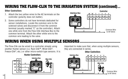
14WIRING THE FLOW-CLIK TO THE IRRIGATION SYSTEM (continued)...Other Controllers1. Attach the two yellow wires to the AC terminals on thecontroller (polarity does not matter).2. Some controllers do not have terminals dedicated forsensor installations. Locate the common wire to thesolenoid valves and disconnect it from the commonterminal (usually marked “C” on the controller). Attachone white wire from the <strong>Flow</strong>-<strong>Clik</strong> Interface Box to thecommon terminal. Attach the other white wire to thecommon wire leading to the valve.WIRING WHEN USING MULTIPLE SENSORS............................................The <strong>Flow</strong>-<strong>Clik</strong> can be wired to a controller already usinganother <strong>Hunter</strong> sensor (i.e. Rain-<strong>Clik</strong>, Wind-<strong>Clik</strong> ® ,Freeze-<strong>Clik</strong> ® , etc.) or other micro-switch type sensors. It isSENSENACAC<strong>Hunter</strong> ControllersWYYInterface BoxWMini-<strong>Clik</strong>Interface BoxYWACYAC1 2 3 4Common Wireto All Valvesimportant to make sure that, when using multiple sensors,they are connected in series.Other ControllersInterface BoxYWACYACCCWController1 2 3Mini-<strong>Clik</strong>WCommon Wireto All Valves