
You also want an ePaper? Increase the reach of your titles
YUMPU automatically turns print PDFs into web optimized ePapers that Google loves.
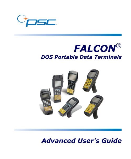
FALCON ®DOS Portable Data TerminalsAdvanced <strong>User</strong>’s Guide
CONTENTSAbout this Guide ..........................................................................................ixOverview ................................................................................................................xFalcon ® Model Numbers .......................................................................................xRadio Frequency Interference ...............................................................................xiiStyle Conventions............................................................................................... xiiiDocument Conventions .............................................................................. xiiiKeys and Keystroke Conventions ................................................................ xiiiTechnical Support ...............................................................................................xivChapter 1: Using Falcon DOS Portable Terminals ............................................ 1-1Overview ............................................................................................................ 1-2Programming the Laser Triggers......................................................................... 1-2Programming the Enter Keys.............................................................................. 1-3Using PC Cards.................................................................................................. 1-4Opening the PC Card Slot Cover................................................................1-5Inserting a PC Card.....................................................................................1-6Card Recognition and Configuration ..........................................................1-7Removing a PC Card ..................................................................................1-8The Serial Port ................................................................................................... 1-8The IR Serial Port .............................................................................................. 1-8The Disk Drives ................................................................................................. 1-9Configuring the Falcon.....................................................................................1-10Transferring Files.............................................................................................. 1-11An Example...............................................................................................1-12Advanced <strong>User</strong>’s Guidei
ContentsChapter 2: The Falcon Configuration Utility ....................................................... 2-1Overview ............................................................................................................2-2Installing the Falcon Configuration Utility .........................................................2-2Using the Falcon Configuration Utility ..............................................................2-3Main Menu ................................................................................................ 2-3The Custom Configuration Menu.............................................................. 2-5The File Configuration Windows............................................................... 2-9The Program Settings Windows ............................................................... 2-16The Comm Settings Dialog Box............................................................... 2-20The File Transfer Window ....................................................................... 2-21Chapter 3: Using File Transfer Programs ............................................................. 3-1XFER32Using XFER32......................................................................................3-2XFER32XFER32 Setup.............................................................................. 3-2General Tab................................................................................................ 3-3Transfer Tab............................................................................................... 3-5Logging Tab ............................................................................................... 3-7Host Mode .........................................................................................................3-8Sending and Receiving Data ...............................................................................3-8Send File (to Portable)................................................................................ 3-9Receive File (from Portable)........................................................................ 3-9Using XFER .....................................................................................................3-10Syntax and Parameters.............................................................................. 3-11The XFER_ARGS Environment Variable................................................. 3-26Multiple-Option Blocks ........................................................................... 3-27The Modem-Initialization File.................................................................. 3-29Performance ............................................................................................. 3-32Error Codes .............................................................................................. 3-34Chapter 4: The Falcon 4-Slot Dock ......................................................................... 4-1Overview ............................................................................................................4-2Operating Modes................................................................................................4-2The 4SLOT.SYS Device Driver..........................................................................4-3Transferring Files with XFER .............................................................................4-4Setting the Baud Rate .........................................................................................4-5Chapter 5: Disk Drives, Organization, Software, & Configurations ............ 5-1Overview ............................................................................................................5-2Disk Drives and Files..........................................................................................5-2Structure..................................................................................................... 5-2Drive A....................................................................................................... 5-3Drive B....................................................................................................... 5-4iiFalcon ® DOS Portable Terminals
ContentsDrive C....................................................................................................... 5-6Drive D ...................................................................................................... 5-6Additional Drives........................................................................................ 5-7Other System Software...................................................................................... 5-7BIOS and DOS .......................................................................................... 5-7PC Card and RF Networking Software....................................................... 5-8System Configurations ....................................................................................... 5-8Default Configuration ................................................................................ 5-8I/O PC Card Support Configuration .......................................................... 5-9Chapter 6: System Utilities .........................................................................................6-1Chapter Conventions......................................................................................... 6-2CFGDEV.SYS ................................................................................................... 6-3CFGIO.EXE...................................................................................................... 6-4COMIO.COM.................................................................................................. 6-5DECODE.SYS .................................................................................................. 6-6FLASHDSK.SYS ............................................................................................... 6-7FORMAT.COM ............................................................................................... 6-8LOCK.COM..................................................................................................... 6-9ORGANIZE.COM ......................................................................................... 6-10PM.COM........................................................................................................ 6-11VDISK.SYS ..................................................................................................... 6-13XFER.EXE....................................................................................................... 6-14Chapter 7: Resetting the Falcon ...............................................................................7-1Overview............................................................................................................ 7-2Warm Boot........................................................................................................ 7-2Cold Boot .......................................................................................................... 7-3Safe Boot............................................................................................................ 7-4Hardware Reset.................................................................................................. 7-5Chapter 8: Using PC Cards ..........................................................................................8-1Overview............................................................................................................ 8-2Uses of PC Cards........................................................................................ 8-2PC Card Drivers ................................................................................................ 8-3Appendix A: Connector Configurations .................................................................. A-1Overview............................................................................................................A-2Falcon Portable Terminals .................................................................................A-2Laser-Scanner Connector ............................................................................A-2Serial Port Jack............................................................................................A-3Advanced <strong>User</strong>’s Guideiii
ContentsSerial IR Port..............................................................................................A-4Falcon Dock ...................................................................................................... A-525-Pin Connector.......................................................................................A-5Falcon 4-Slot Dock............................................................................................ A-6Host-Interface Cable ..................................................................................A-7Dock-Network Cable Jacks.........................................................................A-7Appendix B: ROM-DOS Commands ..........................................................................B-1Command Overview.......................................................................................... B-2ROM-DOS vs. MS-DOS .................................................................................. B-4Command Descriptions..................................................................................... B-5ATTRIB ............................................................................................................ B-6BUFFERS.......................................................................................................... B-7CHKDSK.......................................................................................................... B-8COMMAND .................................................................................................... B-9DELTREE....................................................................................................... B-11DIR ................................................................................................................. B-12FCBS............................................................................................................... B-14FIND .............................................................................................................. B-15HELP .............................................................................................................. B-16NEWFILE....................................................................................................... B-16PRINT ............................................................................................................ B-17SHARE............................................................................................................ B-19SWITCHES .................................................................................................... B-20TREE .............................................................................................................. B-20VER................................................................................................................. B-21XCOPY ........................................................................................................... B-22Appendix C: Programming Parameters .................................................................. C-1Overview ...........................................................................................................C-2Code 39............................................................................................................C-3Interleaved 2 of 5..............................................................................................C-3Matrix 2 of 5.....................................................................................................C-3Standard 2 of 5 .................................................................................................C-3Code 11............................................................................................................C-4Codabar/Ames ..................................................................................................C-4MSI ..................................................................................................................C-4Code 93............................................................................................................C-4Universal Product Code-A (UPC-A).................................................................C-4Universal Product Code-E (UPC-E) .................................................................C-5ivFalcon ® DOS Portable Terminals
ContentsEuropean Article Numbering (EAN) /Japan Article Numbering (JAN)........................................................................C-5UPC, EAN, JAN Extensions.............................................................................C-5Code 128 ..........................................................................................................C-5Labelcode 4/5....................................................................................................C-5Other Controls .................................................................................................C-5Appendix D: Bar Codes .................................................................................................. D-1Predefined Defaults........................................................................................... D-2Code 39 ............................................................................................................ D-2ENABLE ................................................................................................... D-2MINIMUM LENGTH............................................................................. D-2MAXIMUM LENGTH ............................................................................ D-2ENABLE CHECKSUM............................................................................ D-2SEND CHECKSUM ................................................................................ D-2FULL ASCII MODE ................................................................................ D-2Interleaved 2 of 5 ............................................................................................. D-3ENABLE ................................................................................................... D-3MINIMUM LENGTH............................................................................. D-3MAXIMUM LENGTH ............................................................................ D-3ENABLE CHECKSUM............................................................................ D-3SEND CHECKSUM ................................................................................ D-3USE LENGTHS 6 AND 14 ONLY (case code) ........................................ D-3Matrix 2 of 5 .................................................................................................... D-3ENABLE ................................................................................................... D-3MINIMUM LENGTH............................................................................. D-4MAXIMUM LENGTH ............................................................................ D-4Standard 2 of 5 ................................................................................................ D-4ENABLE ................................................................................................... D-4MINIMUM LENGTH............................................................................. D-4ENABLE CHECKSUM............................................................................ D-4SEND CHECKSUM ................................................................................ D-4MAXIMUM LENGTH ............................................................................ D-5ENABLE CHECKSUM............................................................................ D-5SEND CHECKSUM ................................................................................ D-5Code 11 ........................................................................................................... D-5ENABLE ................................................................................................... D-5MINIMUM LENGTH............................................................................. D-5USE 2-BAR START/STOP....................................................................... D-5Codabar/Ames ................................................................................................. D-6CODABAR ENABLE ............................................................................... D-6AMES ENABLE........................................................................................ D-6Advanced <strong>User</strong>’s Guidev
ContentsMINIMUM LENGTH............................................................................. D-6MAXIMUM LENGTH ............................................................................ D-6MAXIMUM LENGTH ............................................................................ D-6REQUIRE 2 CHECK DIGITS ................................................................ D-6SEND CHECK DIGIT(S)........................................................................ D-6MSI ..................................................................................................................D-7ENABLE ................................................................................................... D-7MINIMUM LENGTH............................................................................. D-7MAXIMUM LENGTH ............................................................................ D-7SEND STOP/START............................................................................... D-7CODABAR-TO-CLSI CONVERSION................................................... D-7WIDE INTERCHARACTER GAPS ALLOWED ................................... D-7Code 93 ............................................................................................................D-8ENABLE ................................................................................................... D-8MINIMUM LENGTH............................................................................. D-8MAXIMUM LENGTH ............................................................................ D-8REQUIRE 2 CHECK DIGITS ................................................................ D-82ND CHECK DIGIT MOD 11 ............................................................. D-8SEND CHECK DIGIT(S)........................................................................ D-8Code 128 ..........................................................................................................D-8ENABLE ................................................................................................... D-8MINIMUM LENGTH............................................................................. D-9MAXIMUM LENGTH ............................................................................ D-9Labelcode 4/5 ...................................................................................................D-9ENABLE ................................................................................................... D-9CONVERT............................................................................................... D-9UPC-A (Universal Product Code-A) ....................................................................D-9ENABLE UPC-A ...................................................................................... D-9ENABLE UCC/EAN 128 ......................................................................... D-9UPC-E (Universal Product Code-E)....................................................................D-10USE SYSTEM DIGIT 0 ......................................................................... D-10USE SYSTEM DIGIT 1 ......................................................................... D-10CONVERT UPC-E TO UPC-A ............................................................ D-10SEND SYSTEM DIGIT ......................................................................... D-10SEND CHECK DIGIT .......................................................................... D-10SEND SYSTEM DIGIT ......................................................................... D-10SEND CHECK DIGIT .......................................................................... D-10CONVERT UPC-A TO EAN-13........................................................... D-10EAN (European Article Numbering)/ JAN (Japan Article Numbering) ...................... D-10ENABLE EAN-8/JAN-8 ......................................................................... D-10UPC/EAN/JAN Extentions ............................................................................D-11ALLOW 2-DIGIT EXTENSIONS......................................................... D-11viFalcon ® DOS Portable Terminals
ContentsALLOW 5-DIGIT EXTENSIONS......................................................... D-11REQUIRE EXTENSIONS ..................................................................... D-11ENABLE EAN-13/JAN-13 ..................................................................... D-11CONVERT EAN-13 TO ISBN.............................................................. D-11SEND EAN/JAN CHECKSUM ............................................................. D-11Other Controls .............................................................................................. D-11AUTOTERMINATOR .......................................................................... D-11AUTO-OFF TIMER............................................................................... D-11SEND SYMBOLOGY IDENTIFIER ..................................................... D-12GOOD-READ BEEP TONE (in Hertz)................................................... D-12NUMBER OF GOOD-READ BEEPS ................................................... D-12GOOD-READ BEEP DURATION ....................................................... D-12BEEPER VOLUME................................................................................ D-12ERROR BEEP TONE (in Hertz).............................................................. D-13LONG-RANGE TRIGGER MODE ...................................................... D-13SPOTTING BEAM ENABLE ................................................................ D-13SPOT BEAM TIMEOUT (in seconds).................................................... D-13RELEASE SCAN TIMEOUT (in seconds).............................................. D-13KEYPRESS SOUND............................................................................... D-13ENABLE CTL-ALT-DEL REBOOT...................................................... D-13ENABLE TRIGGER PROGRAMMABILITY........................................ D-14BACKLIGHT AUTO-OFF TIMEOUT................................................. D-14DOUBLE KEY ACTION MODE.......................................................... D-14DOUBLE KEY ACTION TIMEOUT .................................................. D-14Index...............................................................................................................xvAdvanced <strong>User</strong>’s Guidevii
ContentsNOTESviiiFalcon ® DOS Portable Terminals
Preface:About this GuidePREFACE CONTENTSOverview ................................................................. viiiFalcon ® Model Numbers ......................................... viiiRadio Frequency Interference......................................xStyle Conventions...................................................... xiDocument Conventions ......................................... xiKeys and Keystroke Conventions............................ xiTechnical Support .................................................... xii
About this GuideOverviewThis manual is a supplement to the Falcon ® DOS Portable Terminals <strong>User</strong>’sGuide. It contains the following technical information on Falcon portables:• System configuration• Disk drives• Using PC cards• Resetting the Falcon• Using the 4-Slot Dock• DOS commands• Utilities• Connector configurations• Programming parameters• Bar codes for setting parametersThis book is provided as a reference guide for System administrators,Developers, and Programmers who want to create end-user solutions for FalconDOS portable terminals. It is not intended for use by first-time Falcon users.Falcon ® Model NumbersFalcon DOS portable data terminals are handheld computers designed for datacollection. The product title, “Falcon” refers to any or all of the DOS portablemodels identified in the table below of Falcon® Portable Models.Where information in this manual applies only to specific models, thosemodels are clearly identified by the model icon as shown in the first column.The Falcon DOS portable line includes 8-line and 16-line models. Both the 8-line and the 16-line Falcon models are available in batch and wireless (radiofrequency, or RF) configurations. Wireless models provide instantcommunication of data between the unit and a host computer.xFalcon ® DOS Portable Terminals
Falcon ® Model NumbersTable 1: Falcon ® Portable ModelsModelModelNumber8-LineDisplay16-LineDisplayBatchPortableRFPortable310 315 320 325 330 335 340 345 The 31X icon refers to both the Falcon 310 and the Falcon 315. As the tableon page xi notes, the Falcon 310 is a batch portable model and the Falcon 315is an RF portable model. On the cover of this manual, the Falcon 31X isrepresented by the Falcon 315, in the lower left corner, with an 8-line displayscreen.The 32X icon refers to both the Falcon 320 and the Falcon 325. As the tableon page xi notes, the Falcon 320 is a batch portable model and the Falcon 325is an RF portable model. The Falcon 32X has many features in common withthe Falcon 31X. These models are often grouped together throughout thismanual. On the cover of this manual, the Falcon 32X is represented by theFalcon 325, second from the upper left, with a 16-line display screen.The 33X icon refers to both the Falcon 330 and the Falcon 335. As the tableon page xi notes, the Falcon 330 is a batch portable model and the Falcon 335is an RF portable model. The Falcon 33X model has many features in commonwith the Falcon 32X model. On the cover of this manual, the Falcon 330portable is the smaller, ergonomic model shown in the upper right corner ofthe grouping.Advanced <strong>User</strong>’s Guidexi
About this GuideThe 34X icon refers to both the Falcon 340 and the Falcon 345. As the tableon page xi notes, the Falcon 340 is a batch portable model and the Falcon 345is an RF portable model. The Falcon 34X introduces the pistol grip. Thismodel operates in every other way identically to the Falcon 33X. On the coverof this manual, the Falcon 340 portable is the one with the pistol grip, shownin the lower right corner of the grouping.Radio Frequency InterferenceThis device complies with Part 15 of the FCC Rules. Operation is subject tothe following two conditions:1. This device may not cause harmful interference, and2. This device must accept any interference received, including interferencethat may cause undesired operation.This Class A digital apparatus complies with Canadian ICES-003.Cet appareil numérique de la Classe A est confirme à la normeNMB-003 du Canada.This equipment has been tested and found to comply with the limits for aClass A digital device, pursuant to Part 15 of the FCC Rules. These limits aredesigned to provide reasonable protection against harmful interference in aresidential installation. This equipment generates, uses and can radiate radiofrequency energy and, if not installed and used in accordance with theseinstructions, may cause harmful interference to radio communications.However, there is no guarantee that interference will not occur in a particularinstallation. If this equipment does cause interference to radio or televisionreception, which can be determined by turning the equipment off and on, theuser is encouraged to try to correct the interference by one or more of thefollowing measures:• Reorient or relocate the receiving antenna.• <strong>Inc</strong>rease the separation between the equipment and receiver.• Connect the equipment into an outlet on a circuit different from whichthe receiver is connected.• Consult the dealer or an experienced radio/TV technician for help.xiiFalcon ® DOS Portable Terminals
Style ConventionsStyle ConventionsDocument ConventionsFormatting conventions are used throughout this guide as a method ofproviding consistency for notes, cautions, and warnings.NotesCautionsWarningsNotes appear throughout the manual to provide additional information on atopic, including technical details, exceptions to instructions and otherpertinent information. These notes are identified by the notepad symbol to theright and bold italics text.Cautions appear when there is information for the user that is stronglyrecommended. They are identified by the exclamation mark in a triangle andbold italics text. This text appears in gold bold italics text if the user isviewing the manual in electronic PDF form on their computer.Warnings appear when there is something of extreme importance for the userto be know prior to proceeding. They are identified by the exclamation mark ina triangle and bold italics text. This text appears in red bold italics text if theuser is viewing the manual in electronic PDF form on their computer.Keys and Keystroke ConventionsPortable keys and keystroke conventions are used throughout this manual toidentify the difference between a key on the portable and keystrokes input bythe user. Brackets such as: “” indicate a key on the Falcon Portable.Data or keystrokes entered by the user are printed in a monospacedtypeface.Advanced <strong>User</strong>’s Guidexiii
About this GuideTechnical SupportPSC Website Technical SupportThe most comprehensive source for technical support and information for PSCproducts is the PSC website: www.pscnet.com. Select Support from the sidebarfor technical support. The site offers product registration, warrantyinformation, answers to frequently asked questions (product FAQs), productmanuals, product tech notes, software updates, patches, demos, andinstructions for returning products for repair.Reseller Technical supportAnother excellent source for technical assistance and information is anauthorized PSC reseller. A reseller is directly acquainted with specific types ofbusinesses, application software, and computer systems and, therefore, is in thebest position to provide individualized assistance.E-Mail Technical SupportIf the solution to a technical support question is not available through the PSCwebsite or a local reseller, contact PSC technical support directly via E-mail atTechSupport@pscnet.com.Telephone Technical SupportFor those without E-mail access, please call (541) 984-3092.PSC Solutions GroupFor advanced, cost-effective services, contact the PSC Solutions Group (PSG)at (888) 583-3008 or psg@pscnet.com. Or go to the PSG webpage atwww.pscnet.com/html/psc_solutions_group_psg.htm.xivFalcon ® DOS Portable Terminals
1Using Falcon DOSPortable TerminalsCHAPTER CONTENTSOverview..................................................................1-2Programming the Laser Triggers..............................1-2Programming the Enter Keys...................................1-3Using PC Cards .......................................................1-4Opening the PC Card Slot Cover .........................1-5Inserting a PC Card..............................................1-6Card Recognition and Configuration....................1-7Removing a PC Card............................................1-8The Serial Port.........................................................1-8The IR Serial Port....................................................1-8The Disk Drives.......................................................1-9Configuring the Falcon..........................................1-10Transferring Files ...................................................1-11An Example ........................................................1-12
Using Falcon DOS Portable TerminalsOverviewThis chapter provides information about advanced features of Falcon DOSportable terminals. It does not cover Falcon basics, such as use of the keypadand viewport. For basic information about the Falcon, refer to the Falcon DOSPortable Terminals <strong>User</strong>’s Guide.Programming the Laser TriggersNormally, the left trigger operates the Falcon laser or another bar code readerattached to the Falcon, and the right trigger toggles the Falcon in and out ofAlpha mode (models 31x) or Function mode (models 32x). One or both of thelaser triggers can be reprogrammed to act as equivalents of keypad keys.To turn a trigger into an alias for a keypad key:1. Hold down the and keys.2. Press the key and the program-trigger cursor ( ) appears inthe viewport.3. Press the trigger to be changed.4. Press the key to be assigned to the trigger.The following keys are validselections: 1. First, hold down the and keys and press the key.The program-trigger icon ( ) should appear in the viewport.2. Press the trigger that is to be changed.3. Press the new key assigned to the trigger.The following keys are validselections: 1-2 Falcon ® DOS Portable Terminals
Programming the Enter KeysFor example, to turn the right trigger on a model 32x into an alias for the key:1. Hold down the and keys and press the key toenter program-trigger mode.2. Then press and release the right trigger.3. Press the key.The right trigger now works as a second key.To change a reassigned trigger back to a laser trigger:1. Put the Falcon into program-trigger mode.2. Press the trigger twice.Falcon 33x and 34x models do not have programmable laser triggers. The key is only key for operating the laser.Programming the Enter KeysFalcon 33x and 34x models allow reprogramming of one of the keys.One key may be reprogrammed from a list of available keys. There isno option for swapping the function of the keys. However, if one keyis reprogrammed, the other key automatically becomes the key.This features only is only available on a 38-key keypad.Figure 1-1: Location of the Enter keys on the Falcon 33X and 34XAdvanced <strong>User</strong>’s Guide 1-3
Using Falcon DOS Portable TerminalsTo program an key:1. Hold down the key sequence - and press the desired key to re-program.Press the key then the key, not the key then (or )key.2. The Program Trigger Icon ( or ) appears on the right of theLCD, indicating which key is to be reprogrammed.3. Select the key sequence to reprogram the key. The followingkeys are valid sections: All of these functions, except the character are the shifted state ofanother key. When selecting the key, do not enter mode first. To assign the left key to , press ---. Falcons 33xand 34x automatically translate the keypress into the key.Using PC CardsThe Falcon has a slot for plugging in PC cards, and each unit is factoryequippedwith PhoenixCARD Manager Plus PC card drivers. PC cards providesuch features as network connectivity, modem connectivity, and wirelesscapability. Their primary purpose in the Falcon is to provide additionalmemory storage by functioning as a disk drive. (See page page 1-9 forinformation about the Falcon’s drives.)The PC card slots of the Falcon 33x and 34x are not user accessible, but function inthe same manner as the Falcon 32x for software installation, use and general features.1-4 Falcon ® DOS Portable Terminals
Using PC CardsOpening the PC Card Slot CoverThe PC card slot is located near the bottom on the back of the Falcon (refer toFigure 1-2). The slot is protected by a cover. Detach the elastic hand strap onthe back of the Falcon by pulling its hook out of the holder near the base. If theslot cover is secured by a screw, loosen the screw. Then, while pressing theround button above the slot cover, slide the cover out and away from theFalcon.Figure 1-2: Removing the PC Card Slot Cover on a Falcon 3101. Remove the hand strap hookfrom the holder (hand strapnot shown).2. Loosen the locking screw.*3. Press the round button torelease the cover.4. Pull the cover out.*The locking screw cannotbe completely removedfrom the PC card slot cover.To keep the screw fromcatching on the unit, turnAdvanced <strong>User</strong>’s Guide 1-5
Using Falcon DOS Portable TerminalsInserting a PC CardAll PC cards have two rows of small sockets on one end (refer to Figure 1-3).The cards also have face-up and face-down sides. The card manufacturer’s labelis usually on the face-up side.Turn the Falcon off before inserting or removing a PC card.Figure 1-3: A Typical PC CardSocketsTo insert a PC card into a Falcon complete the following steps:1. Start with the Falcon face down and the PC card face up.2. Insert the end of the card with the sockets into the card slot (refer toFigure 1-4).3. Use the tracks inside the slot to help guide the card.4. Push the card firmly into the slot until the ejector tab slides out.5. Replace the PC card slot cover.1-6 Falcon ® DOS Portable Terminals
Using PC CardsFigure 1-4: Inserting a PC Card into the SlotDo not force the cardinto the slot. It shouldslide in easily.Ejector tabThe PC card slot on the Falcon is designed so a card cannot be inserted upside downor backward. If the card does not push into the slot easily, make sure the card ispositioned properly. Put the end with the sockets into the slot first. Then flip the cardupside down and try to insert it again.Card Recognition and ConfigurationOnce the card is inserted into the slot complete the following steps:1. Turn the Falcon on. The Falcon will attempt to recognize and configurethe card.2. If the Falcon responds with one beep, the PhoenixCARD Manager Plusdrivers successfully recognized and configured the card.3. If the Falcon does not beep, the drivers might not be loaded in theFalcon, or the beeper may be disabled.In some cases, drivers provided by a specific card’s vendor are responsible forconfiguring the card. If one of these cards is being used, there may be no audiosignals for card configuration. See the configuration instructions that came with thecard.Advanced <strong>User</strong>’s Guide 1-7
Using Falcon DOS Portable TerminalsRemoving a PC CardA tab inside the PC card slot ejects the installed card (refer to Figure 1-4). Pushthe end of the ejector tab into the Falcon. The PC card should slide partwayout of the slot. Hold the card by the edges and pull it the rest of the way out.The Serial PortFalcon models 31x and 32x have a port for serial communications with a PC.The serial port is located at the base of the Falcon 31x and 32x (refer toFigure 1-5). Designated as COM1, it is a 10-pin telephone-style jack providing astandard RS-232 connection.With a serial cable connected to it, the port allows communications with a hostcomputer or any serial device, such as a printer or modem. The serial port alsoprovides a connection for communications and battery recharging in theFalcon Dock and Falcon 4-Slot Dock.Figure 1-5: The Serial Port on a Falcon 320For the wiring configuration of the serial port, refer to Appendix A, on page A-1.The IR Serial PortThe serial port of the Falcon 33x and 34x is a half duplex IR port. Refer toFigure 1-6. Through software commands, the port may be setup for IR or amodified RS-232 serial communication.1-8 Falcon ® DOS Portable Terminals
The Disk Drives• In IR mode, all physical communications meet the IrDA physical layerspecification.• In the modified RS-232 serial mode, the IR port is used to transmit RS-232 level data out the IR port. The third pin along the bottom of theFalcon 33x and 34x is used to receive RS-232 level data.• In general, the IR mode is used when communicating to other IR devices(printers, computers, etc.) and the modified RS-232 mode is used tocommunicate with the dock for host communications.• The Falcon 33x and 34x do not propagate the RS-232 hardware signalssuch as RTS, CTS, DTR, DSR, RI, and DCD.When using Zmodem, flow control must be the same on both sides of thetransmission. Normally, XFER defaults to RTS/CTS flow control. On the Falcon 33x and34x, it defaults to Xon/Xoff. When transferring files between a 33x or 34x and the hostPC, make sure the PC is also using Xon/Xoff. See the /F option on page 3-18 formore details.Figure 1-6: The IR Serial Port on the Falcon 33x and 34xThe Disk DrivesThe Falcon contains four logical disk drives that provide storage for systemfiles, applications, and data.Drive ADrive BDrive A is a read-only drive. Its contents cannot be changed.Drive B is a read-only drive used to store system utilities and to initialize theboot process. Its contents cannot be changed.Advanced <strong>User</strong>’s Guide 1-9
Using Falcon DOS Portable TerminalsDrive CDrive DAdditionalDrivesDrive C is a flash disk drive that allows full read and write access. This drivecontains DOS command files, PC card drivers, Falcon utilities, and executablefiles and associated files for applications. It may also contain additionalconfig.sys and autoexec.bat files to configure the Falcon to runapplications.Drive D is a RAM disk drive. The RAM disk is used primarily for data storage.Programs that need to be loaded into memory and then quickly removed frommemory can also be placed here. Drive D can also be used for scratch disk spaceor temporary files.Additional RAM disk drives may be configured using VDISK.SYS. This canbe done using the configuration utility (refer to page 2-12) or directly inCONFIG.SYS (refer to page 6-13.)The Falcon may also be configured to use PC ATA flash cards. The PC Card isidentified as a hard disk drive by the operating system. This drive may be usedfor safe and permanent storage of data.The Falcon may have other additional logical drives that are network drivesaccessed via wireless access points.The drive letters for the additional RAM, ATA, and network drives will beassigned at loading. The drive letters will begin at Drive E.Configuring the FalconIf the Falcon is not already configured, use the Falcon Configuration Utility toinstall applications and set options for bar code scanning. The FalconConfiguration Utility operates under Windows® 95, Windows® 98,Windows® 2000, Windows® ME, and Windows® NT. For instructions onusing the utility, refer to Chapter 2.Bar codes can also be used to change settings in the Falcon. Appendix D containsthe bar codes for most common settings.1-10 Falcon ® DOS Portable Terminals
Transferring FilesTransferring FilesTo transfer data or program files, connect the Falcon unit to the host computerwith any of the following accessories:• Falcon serial cable• Falcon Dock• Falcon 4-Slot Dock (Only available for Falcon models 31x and 32x.)The Falcon application may have simple file-transfer options, or use the FalconXFER utility.When using the Falcon Configuration Utility to transfer files (refer to Chapter2), the configuration utility runs XFER automatically. If the configurationutility is not used, XFER requires entering commands at the DOS commandline on both the Falcon and the PC.Falcon and the PC.The XFER utility is loaded into the Falcon at the factory and placed on driveB. If the PATH statement has not been changed, XFER can be run from anydrive on the Falcon. However, before running XFER32 on a PC, install theFalcon Configuration Utility onto the hard drive. By default,XFER32xfer32 is placed in the directory: \PDTFilesThe command line syntax for XFER is as follows:XFER [/option1 [/option2] . . .] filenameUse a slash (/) or a hyphen (-) to denote options, and use uppercase orlowercase letters. Options can be placed before or after the filename on thecommand line. A sample command line appears at the end of this section.Transfer a single file by using XFER with the Xmodem protocol (the defaultprotocol) or transfer multiple files with the Xmodem or Zmodem protocol.Basic options for Xmodem protocol are listed and described in Table 1-1 onpage 1-12. The “Default” column indicates whether the option is used (“On”)or ignored (“Off”) if not included in the command line. For options that havetwo or more possible values, the default value is given.Advanced <strong>User</strong>’s Guide 1-11
Using Falcon DOS Portable TerminalsTable 1-1: XFER Options (Xmodem Protocol)Option What It Does Defaultfilename Identifies the file to be transferred or received. None#B#D#Specifies the communication port to use. Replace the #symbol with the desired setting:1 = COM1 2 = COM2Specifies the baud rate. Replace the # symbol with thedesired setting:2400 4800 9600 19200 38400 57600115200Specifies the number of seconds for XFER to wait foractivity before cancelling the transfer. Replace the #symbol with the desired number of seconds for thetimeout delay. Acceptable values are 0 (no timeout)through 65,535.11920060H or ? Displays help for the XFER command. OffOOverwrites an existing file with a new file having the samename.OffR Receives the specified file. OffT Transmits the specified file. OnAn ExampleTo transfer a file named foo from a PC to a Falcon using Xmodem protocol,use the following command lines.On the PC: xfer foo . This command causes the computer to send thespecified file using XFER’s default settings.On the Falcon: xfer /r foo . This command causes the Falcon to receivethe specified file transmitted from the PC.For more information about XFER, including Zmodem options, refer to Chapter 3.1-12 Falcon ® DOS Portable Terminals
2The FalconConfiguration UtilityCHAPTER CONTENTSOverview..................................................................2-2Installing the Falcon Configuration Utility .............2-2Using the Falcon Configuration Utility ...................2-3Main Menu ..........................................................2-3The Custom Configuration Menu........................2-5The File Configuration Windows .........................2-9The Program Settings Windows..........................2-16The Comm Settings Dialog Box .........................2-20The File Transfer Window ..................................2-21
The Falcon Configuration UtilityOverviewThe Falcon Configuration utility provides a simple way to change theFalcon’s settings for bar code symbologies and serial communications. It canalso be used to load programs and files into the Falcon. The utility runs underWindows® 95, Windows® 98, Windows® 2000, Windows® Me, andWindows ® NT. This chapter describes how to install the utility and use it toconfigure the Falcon.Installing the Falcon Configuration UtilityTo install the Falcon Configuration utility complete the following steps:1. Insert the CD labeled Falcon Utility Software and <strong>Manual</strong>s into thePC’s CD drive.2. Wait for the autoplay to open. If the autoplay does not come up, accessthe CD using Windows Explorer. Go to the install directory and runsetup.exe.3. At the autoplay menu, select the Falcon Configuration utility.4. Copy the file to your desktop or run it from the CD.5. In the Installation Options window, select the radio components to beinstalled, if any.6. Click on the Next button to continue.7. In the RF Installation Options window, uncheck the check boxes forany components not to be installed.8. Click on the Next button to continue to the next dialog box.9. In the Select a Group Name window, select a program group in whichto place the Falcon Configuration utility icons.10. Click on the Next button to continue.11. Specify the directory in which to place the Falcon Configurationutility files in the next window.12. Click on the Next button to continue.2-2 Falcon ® DOS Portable Terminals
Using the Falcon Configuration Utility13. Continue following the instructions in the dialog boxes, replacing thefirst disk with the second, and then the third disk.14. When the installation is complete, click on the Finish button in thefinal window.Using the Falcon Configuration UtilityMain MenuTo start the Falcon Configuration utility, double-click on the FALCON iconin the program group. The first screen that appears is the main menu.This menu provides access to all the configuration settings for the Falcon(Figure 2-1 on page 2-4).Default 1. Select this option to load the original factory configuration into theFalcon unit. The Configuration utility prepares files to be transferred tothe Falcon and opens the Important dialog box (Figure 2-2).2. Check the file lists in both sections of the dialog box to see if they arecorrect and complete.3. To add, delete, or rename files, select Cancel from the dialog box.4. Use the Custom selection in the main menu to build custom lists.(Refer to page 2-5 through page 2-8 for instructions to create customconfigurations.)5. If the file lists in the dialog box are correct, make sure the Falcon unit isproperly connected to the serial port specified in the Comm Settingsdialog box (refer to page 2-20).6. Run the ld.bat file on the Falcon.Advanced <strong>User</strong>’s Guide 2-3
The Falcon Configuration UtilityFigure 2-1: The Falcon Configuration Utility Main Menu7. Click on the OK button in the Important dialog box (Figure 2-2 on page2-5).CustomCommSettingsTransfer FilesSelect this option to choose or modify configuration files or program files to beloaded into the Falcon unit. See the next section for information on theCustom Configuration menu.Select this option to modify settings for the computer’s serial port. Refer topage 2-20 for information on the Comm Settings dialog box.Select this option to transfer data files between the Falcon and the hostcomputer. Refer to page 2-21 through page 2-24 for information on the FileTransfer window.2-4 Falcon ® DOS Portable Terminals
Using the Falcon Configuration UtilityFigure 2-2: The Important Dialog BoxSelect Product: Select the appropriate radio-button for type the Falcon modelbeing configured: 31x, 32x/33x/34x, or 51x.The Custom Configuration Menu1. Select Custom from the main menu.2. An Open dialog box appears (refer to Figure 2-3 on page 2-6).3. Use this dialog box to select a configuration file from the Configsfolder.• The configuration file contains the information presented whenselecting the File Configuration button on the CustomConfiguration menu.Advanced <strong>User</strong>’s Guide 2-5
The Falcon Configuration UtilityFigure 2-3: The Open Dialog Box for Selecting a Configuration FileIf the Open as read-only check box is selected and changes are made to theconfiguration settings, use a new file name to save the changes.4. When the configuration file is finished loading, a second Open dialogbox appears.5. Use this dialog box to select a program-settings file from the Progsetsfolder.6. The program-settings file contains the information that will be presentedwhen selecting the Program Settings button on the CustomConfiguration menu.7. After the program-settings file is loaded, the Custom Configurationmenu appears (Figure 2-4 on page 2-7).FileConfigurationSelect this option to choose application files to be loaded into the Falcon. Referto page 2-9 through page 2-16 for information about the File Configurationwindows.Configure Files Using: This field shows the configuration file that will be usedto specify the files that will be loaded into the Falcon. Select the check box toload the files. Deselect it to turn this option off.2-6 Falcon ® DOS Portable Terminals
Using the Falcon Configuration UtilityFigure 2-4: The Custom Configuration MenuProgramSettingsSelect this option to view or change settings for bar code symbologies and otherprogrammable Falcon options. Refer to page 2-16 through page 2-20 forinformation about the Program Settings windows.Program Settings Using: This field shows the program-settings file that willbe used. Select the check box to load the program settings. Deselect it to turnthis option off.CommSettingsDownloadSelect this option to view or change serial communications settings for theFalcon. See page 2-20 for information about the Comm Settings dialog box.When finished customizing the Falcon configuration, select this option to loadthe custom configuration into the Falcon.1. When selected, the configuration utility prepares files to be transferred tothe Falcon and opens the Important dialog box (refer to Figure 2-2).Advanced <strong>User</strong>’s Guide 2-7
The Falcon Configuration Utility2. Make sure the Falcon unit is properly connected to the serial portspecified in the Comm Settings dialog box (refer to page 2-20).3. Then run the ld.bat file on the Falcon, and select OK in theImportant dialog box.Select Product: Select the appropriate radio-button for type the Falcon modelbeing configured: 31x, 32x/33x/34x, or 51x.DoneSelect this option to return to the main menu. If changes were made to the fileconfiguration or program settings, one or both of the following promptsappear:Figure 2-5: The Prompt for Saving Changes to the Current File ConfigurationFigure 2-6: The Prompt for Saving Changes to the Current Program SettingsYesNoCancelSelect this option to save the changes. A Save As dialog box will open. Use thedialog box to specify the location and name of the new configuration orprogram-settings file.Select this option to discard the changes.Select this option to return to the Custom Configuration menu withoutsaving or discarding the changes.2-8 Falcon ® DOS Portable Terminals
Using the Falcon Configuration UtilityThe File Configuration Windows1. Select File Configuration from the Custom Configuration Menu2. The first of three File Configuration windows appears. (Figure 2-7)Figure 2-7: The First File Configuration Window3. Use these windows to choose application files to be loaded into theFalcon.Configuration File: This field shows the configuration file used to specify thefiles that will be loaded into the Falcon.SaveAfter adding, editing, or deleting files in the Application Files list, selectSave to save the revised list in the current configuration file or in a new one.Browse 1. Select Browse to use a different configuration file.2. An Open dialog box appears.Advanced <strong>User</strong>’s Guide 2-9
The Falcon Configuration Utility3. Use the Open dialog box to choose a configuration file from theConfigs folder.4. If Browse is selected after making changes in this or any other FileConfiguration window and the changes are not saved, the promptshown in Figure 2-8 appears.Figure 2-8: The File Selection Dialog Box for Adding an Application FileMain Application: This field identifies the default application that will run onthe Falcon after completing the installation.Application Files: This field lists the files associated with the main application.AddSelect this option to include other files to be installed on the Falcon unit. TheFile Selection dialog box opens.Enter path and filename on host PC: Use this field to specify the file to betransferred to the Falcon.Enter path and filename on portable: Use this field to specify the locationand name of the file to be transferred to the Falcon. The name can be the sameas the original file or it can be given a new name.Download File To: Select this check box to have the specified file downloadedto the specified Falcon models.Main Application: Select this check box to have the specified file be the mainapplication on the specified Falcon models.2-10 Falcon ® DOS Portable Terminals
Using the Falcon Configuration UtilityOnly one file can be selected as the main application for a Falcon model family. Toselect another file as the main application, highlight the current one in theApplication Files list in the File Configuration window, select Edit, and turn offthe Main Application switch for that file.OKCancelSelect OK to return to the File Configuration window. The specified sourcefile will appear in the Application Files list.Select Cancel to return to the File Configuration window without adding afile to the Application Files list.Browse 1. Select Browse to use a different configuration file.2. An Open dialog box appears.3. Use the Open dialog box to choose a source file to be included in thecustom configuration.EditSelect a file in the Application Files list and then select Edit to change thesource path or destination path for the file. The Edit File Properties dialogbox opens.Figure 2-9: The Edit File Properties Dialog Box for an Application FileDeleteTo delete a file from the Application Files list, select the file in the list andthen select Delete.Select Product: Select the appropriate radio-button for type the Falcon modelbeing configured: 31x, 32x/33x/34x, or 51x.Advanced <strong>User</strong>’s Guide 2-11
The Falcon Configuration UtilityNextSelect Next to view or change additional file-configuration options for thecustom installation.Done 1. Select Done when finished setting file-configuration options for thecustom installation.2. The second File Configuration window (Figure 2-10) appears if Next isselected in the first window.Figure 2-10: The Second File Configuration WindowConfigurationFileSaveThis field shows the configuration file used to specify the files that will beloaded into the Falcon.After changing selections in this window, select Save to save the revisions inthe current configuration file or in a new one.Browse 1. Select Browse to use a different configuration file.2-12 Falcon ® DOS Portable Terminals
Using the Falcon Configuration Utility2. An Open dialog box appears.3. Use the Open dialog box to choose a configuration file from theConfigs folder.4. If Browse is selected after making changes in this or any other FileConfiguration window and the changes are not saved, the promptshown in Figure 2-5 on page 2-8 appears.Add a 2nd VDISK: Select to add a 2nd VDISK in the extended memory areaon the Falcon. (Refer to page 1-10.)Select Size: Use this drop down list box to select the size of the 2nd disk.ATA Memory Cards: Turn this switch on to transfer drivers for ATA memorycards to the Falcon.I/O Cards: Turn this switch on to transfer drivers for fax/modem cards to theFalcon.Vendor Specific: Turn this switch on to transfer drivers for other types of PCcards.This option loads PC Card drivers for Card and Socket Services only. Genericclient drivers such as ATA or I/O Card drivers are not loaded if this is the onlycard switch turned on.Use this for RF cards that have their own specific client drivers that will beloaded using application files in the first file configuration window. (refer topage 2-9)DOS Files: Turn this switch on to transfer files for DOS commands andutilities to the Falcon.MoreSelect More to add or remove DOS files from the custom installation. TheSelect DOS Files dialog box appears (Figure 2-11 on page 2-14).Highlight DOS files to download to portable: This field lists DOS files thatare available. Files that are highlighted are currently selected to be included inthe custom installation. Click on a file to select it or deselect it.Advanced <strong>User</strong>’s Guide 2-13
The Falcon Configuration UtilityFigure 2-11: The Select DOS Files Dialog BoxDirectory on portable to store DOS files: Use this field to specify where theDOS files should be placed in the Falcon unit.DoneSelect Done to return to the File Configuration window.Select Product: Select the appropriate radio-button for type the Falcon modelbeing configured: 31x, 32x/33x/34x, or 51x.PrevNextSelect Prev to return to the previous file-configuration window.Select Next to move on to the next file-configuration window.The third File Configuration window (Figure 2-12) appears if Next is selectedin the second window.2-14 Falcon ® DOS Portable Terminals
Using the Falcon Configuration UtilityDoneSelect Done when finished setting file-configuration options for the custominstallation.Figure 2-12: The Third File Configuration WindowConfiguration File: This field shows the configuration file used to specify thefiles that will be loaded into the Falcon.SaveAfter selecting options in this window, select Save to save the revisions in thecurrent configuration file or in a new one.Browse 1. Select Browse to use a different configuration file.2. An Open dialog box appears.3. Use the Open dialog box to choose a configuration file from theConfigs folder.Advanced <strong>User</strong>’s Guide 2-15
The Falcon Configuration Utility4. If Browse is selected after making changes in this or any other FileConfiguration window and the changes are not saved, the promptshown in Figure 2-5 on page 2-8 appears.AUTOEXEC.BAT: Select this option to insert new commands into theautoexec.bat file that will be transferred to the Falcon.CONFIG.SYS: Select this option to insert new commands into theconfig.sys file that will be transferred to the Falcon.Text File: Select this option to view or modify any text file that will betransferred to the Falcon.Select Product: Select the appropriate radio-button for type the Falcon modelbeing configured: 31x, 32x/33x/34x, or 51x.PrevDoneSelect Prev to return to the previous file-configuration window.Select Done when finished setting file-configuration options for the custominstallation.The Program Settings Windows1. Select the Program Settings from the Custom Configuration Menuand the first of six Program Settings windows appears.2. Use these windows to view or change settings for bar code symbologiesand other programmable options.• The first window is shown in Figure 2-13 on page 2-17.• The next four windows are similar, and so are not shown.Program Settings File: This field shows the program-settings file that will beloaded into the Falcon.SaveAfter selecting options in this window, select Save to save the revisions in thecurrent program-settings file or in a new one.Browse 1. Select Browse to use a different program settings file.2. The Open dialog box appears.2-16 Falcon ® DOS Portable Terminals
Using the Falcon Configuration Utility3. Use the dialog box to choose a configuration file from the Progsetsfolder.Figure 2-13: The First Program Settings Window4. If Browse is selected after making changes in this or any other ProgramSettings window and the changes are not saved, the prompt shown inFigure 2-6 on page 2-8 appears.On/Off Switches: The smaller white boxes are on/off switches. Click in thebox to toggle a switch.Input Fields: Enter specific settings for parameters in the larger white boxes.(Refer to Appendix C for a table of parameters and settings.)Select Product: Select the appropriate radio-button for type the Falcon modelbeing configured: 31x, 32x/33x/34x, or 51x.Advanced <strong>User</strong>’s Guide 2-17
The Falcon Configuration UtilityPrevNextSelect Prev to return to the previous program-settings window.Select Next to move on to the next program-settings window.Done 1. Select Done when finished making program settings for the custominstallation.2. The sixth Program Settings window (Figure 2-14) appears if Next isselected in the fifth window.Figure 2-14: The Sixth Program Settings WindowProgram Settings File: This field shows the program-settings file that will beloaded into the Falcon.SaveAfter selecting options in this window, select Save to save the revisions in thecurrent program-settings file or in a new one.Browse 1. Select Browse to use a different program settings file.2-18 Falcon ® DOS Portable Terminals
2. The Open dialog box appears.Figure 2-15: The Last Program Settings WindowUsing the Falcon Configuration Utility3. Use the Open dialog box to choose a configuration file from theProgsets folder.4. If Browse is selected after making changes in this or any other FileConfiguration window and the changes are not saved, the promptshown in Figure 2-6 on page 2-8 appears.Spotting Beam Enable: Select to enable the Spotting Beam. This feature isreviewed in the Falcon DOS Portable Data Terminal <strong>User</strong>’s Guide on page58.On/Off Switches: The smaller white boxes are on/off switches. Click in thebox to toggle a switch.Advanced <strong>User</strong>’s Guide 2-19
The Falcon Configuration UtilityInput Fields: Enter specific settings for parameters in the larger white boxes.(Refer to page C-3 for a table of parameters and settings.)Double Action Key Mode: Select Double Strike or Press and Wait as theDouble Action Key Mode. Both selections in the Falcon DOS PortableTerminals <strong>User</strong>’s Guide on page 38.Double Action Key Delay: Select Double Action Key delay. This feature isreviewed in the Falcon DOS Portable Terminals <strong>User</strong>’s Guide on page 38.Drop-Down Lists: Click on the list to view the options, and select the desiredoption.Radio Buttons: Select the desired setting by clicking on it.PrevDoneSelect Prev to return to the previous program-settings window.Select Done when finished making program settings for the custominstallation.The Comm Settings Dialog Box1. Select Comm Settings from the main menu or the CustomConfiguration menu.2. The Comm Settings dialog box (Figure 2-16 on page 2-21) appears.3. Use this dialog box to view or change settings for serial communicationswith the Falcon.2-20 Falcon ® DOS Portable Terminals
Using the Falcon Configuration UtilityFigure 2-16: The Comm Settings Dialog BoxComm Port: Select the desired serial port for the PC to communicate with theFalcon. The default port is COM1.Baud Rate: Select the baud rate for serial communications between the PCand the Falcon. The default is 9600.The File Transfer Window1. When selecting Transfer Files from the main menu, the File Transferwindow appears (Figure 2-18 on page 2-22).2. Use this window to select data files for transfer between the Falcon andthe computer.List File: This field shows the name of the file-list file, when selected.Transfer files can be selected without using or creating a list file.\SaveAfter making changes in the Files to Transfer list, select Save to save therevisions in the current file-list file (if any), in another existing file, or in a newfile.Browse 1. Select Browse to use a different file-list file.2. An Open dialog box appears.Advanced <strong>User</strong>’s Guide 2-21
The Falcon Configuration UtilityFigure 2-17: The File Transfer Window3. Use the dialog box to choose a configuration file from the Filelistfolder.4. If Browse is selected after making changes in this or any other FileTransfer window and the changes are not saved, the following promptappears:Figure 2-18: The Prompt for Saving Changes to the Current File ListYes 1. Select this option to save the changes.2-22 Falcon ® DOS Portable Terminals
Using the Falcon Configuration Utility2. A Save As dialog box will open.3. Use the dialog box to specify the location and name of the new file-listfile.NoCancelSelect this option to discard the changes.Select this option to return to the File Transfer window without saving ordiscarding the changes.Files to Transfer: This field shows the files that will be included in the transferbetween the Falcon and the PC.AddSelect Add to include additional data files in the transfer. The File Selectiondialog box open (Figure 2-19 on page 2-23.)Figure 2-19: The File Selection Dialog Box for Adding a Data FileEnter path and filename on host PC: Use this field to specify the location ofthe file on the PC.Enter path and filename on portable: Use this field to specify the locationand name for the transferred file on the Falcon.OKCancelSelect OK to return to the File Transfer window. The specified data file willappear in the Files to Transfer list.Select Cancel to return to the File Transfer window without adding a file tothe Files to Transfer list.Browse 1. Select Browse to view the files on the computer.2. The Open dialog box appears.3. Use the dialog box to choose a a data file to be included in the transfer.Advanced <strong>User</strong>’s Guide 2-23
The Falcon Configuration UtilityEdit 1. Select a file in the file list and then select Edit to change the source pathor destination path for the file.2. The Edit File Properties dialog box opens (Figure 2-20).Figure 2-20: The Edit File Properties Dialog Box• The fields and buttons in this dialog box are the same as in the FileSelection dialog box above.DeleteReceiveSendDoneTo delete a file from the list, select the file and then select Delete.Select Receive to begin a file transfer from the Falcon to the PC1. When selected, the configuration utility prepares files to be transferred tothe PC and opens the Important dialog box (Figure 2-2 on page 2-5).2. Make certain the Falcon unit is properly connected to the serial portspecified in the Comm Settings dialog box (refer to page 2-20).3. Then run the ld.bat file on the Falcon, and select OK in theImportant dialog box on the computer.4.Select Send to begin a file transfer from the PC to the Falcon.1. The configuration utility prepares files to be transferred to the Falconand opens the Important dialog box (refer to Figure 2-2 on page 2-5).2. Make certain the Falcon unit is properly connected to the serial portspecified in the Comm Settings dialog box (refer to page 2-20).3. Then run the ld.bat file on the Falcon, and select OK in theImportant dialog box.Select Done when finished selecting and transferring files.2-24 Falcon ® DOS Portable Terminals
3Using File TransferProgramsCHAPTER CONTENTSUsing XFER32.........................................................3-2XFER32 Setup......................................................3-2General Tab ..........................................................3-3Transfer Tab..........................................................3-5Logging Tab..........................................................3-7Host Mode...............................................................3-8Sending and Receiving Data ....................................3-8Send File (to Portable) ..........................................3-9Receive File (from Portable)..................................3-9Using XFER...........................................................3-10Syntax and Parameters ........................................3-11The XFER_ARGS Environment Variable ...........3-26Multiple-Option Blocks......................................3-27The Modem-Initialization File............................3-29Performance........................................................3-32Error Codes ........................................................3-34
Using File Transfer ProgramsXFER32Using XFER32When you start XFER32, the XFER32 interface, opens ().Figure 3-1: . XFER32 <strong>User</strong> InterfaceXFER32XFER32 SetupTo prepare for data transfer between the PC and the PT40, click on the Setupbutton to open the Setup dialog box, which contains three tabbed sections.The settings in these dialogs can be modified or customized to meet yourcommunications requirements.3-2 Falcon ® DOS Portable Terminals
XFER32Using XFER32General TabFigure 3-2: File Transfer Setup Definition Form: General TabConnectionEnter the Connection port for file transfers. Select from the list ofdetected serial ports or modems.Baud RateSelect a Baud Rate for serial communicationsfrom the pull-down list. The default value is19200.Advanced <strong>User</strong>’s Guide 3-3
Using File Transfer ProgramsProtocolSelect the file transfer Protocol to use forsending and receiving files. The Protocoldepends upon what the Host system requires.The default value is ZModem.Refer to “XModem vs. ZModem” on page -267 to select thecorrect protocol for your application.XModem XModem does not allow multiple file transfers.ZModem ZModem allows multiple file transfers.ACK/NAK ACK/NAK does not allow multiple file transfers. Do not use ACK/NAK with PSC Falcon DOS units.Maximum Errors Enter the maximum number of Errors permitted before a file transfer isaborted. Range: 1 to 50. 0 specifies no limit to the number of filetransfer errors.Flow Control Select the mechanism used to control the flowof data. Sender and receiver must agree on theflow control method.NoneXON/XOFFRTS/CTSWindow SizeNo flow control used.Software flow control using XON and XOFF characters tocommunicate when to suspend and resume data transfer. Onlyavailable with Z-Modem protocol.Hardware flow control that uses Ready to Send (RTS), and Clear toSend (CTS) serial port lines to communicate when to suspend andresume data transfer.Specifies the amount of data transmitted beforereceiving a response from the receiver.Streaming Sender does not wait for a response before sending all the data.1024-4096 Causes the sender to wait for a response after sending the specifiedamount of data.Crash Recovery Specifies whether or not an attempt is made tocomplete a file transfer at the point of failure.3-4 Falcon ® DOS Portable Terminals
XFER32Using XFER32NeverFollowSenderAlwaysNever attempts to recover from a file transfer.Follows the sender’s Crash Recovery and Overwrite options.Forces an attempt to recover from a file transfer.Transfer TabThis tab establishes file transfer settings. Select the Transfer tab.Figure 3-3: Transfer Tab of the File Transfer UtilitySender Timeout(Seconds)Receiver TimeoutEnter the maximum number of seconds to wait for a connectionwhen sending files. A value of 0 waits indefinitely.Enter the maximum number of seconds to wait for a connectionwhen receiving files. A value of 0 waits indefinitely.Advanced <strong>User</strong>’s Guide 3-5
Using File Transfer ProgramsPath/FilenameTransmissionStrip PathSend PathSpecifyReceiver’s FilePath/NameOverwriteSource Longer orNewerCRCs Don’tMatchAppendAlwaysSource NewerDate/LengthDon’t MatchNeverFile Transfer DefaultEnter a Path/Filename Transmission to control how the senderprocesses the paths and filenames of files to be sent. Only appliesto Z-Modem.Sends only the filename (no path) to the receiver.Sends the filename with path to the receiver.Allows both the filename and path for each file to be altered priorto being sent to the receiver.Select to determine the action the receiver takes when a receivedfile already exists.Overwrites the existing file if the received file is longer or newer.Overwrites the existing file if the CRCs of both files don’t match.Appends the received file to the existing one.Overwrites the existing file with the one received.Overwrites the existing file if the received file is newer.Overwrites the existing file if the dates or lengths of both files don’tmatch.Skips the transfer if the received file already exists.Enter the File Transfer Default folder for storing received files.Use the Browse button to locate a new location.3-6 Falcon ® DOS Portable Terminals
XFER32Using XFER32Logging TabThis tab establishes settings for the communications log. Click the Logging tab.Figure 3-4: Logging Tab of the File Transfer UtilityLog To FileLog To ScreenAppend to LogLog Path/FilenameBrowseSpecifies that the log is to be written to a text file.Specifies that the log is displayed on screen.This option becomes available when you select Log to File. Whenenabled, Append to Log adds log information to the end of the log file.If not enabled, new log information replaces the previous log file.Specify the location for storing the communications log.If a path is not given, the file is stored in the Default File Transferfolder.Use the Browse button to locate a new log file.Advanced <strong>User</strong>’s Guide 3-7
Using File Transfer ProgramsHost ModeHost Mode is a method of receiving files using the Z-Modem protocol. Itcontinuously waits for files and receives them using the filenames specified bythe sender. Once files have been received, it goes back to waiting for additionalfiles. Select Transfer Files > Host Mode from the menubar.Figure 3-5: Host Mode WindowSending and Receiving DataUPG uses the File Transfer Manager to transfer data (collection, validation, and INIfiles) between a portable data collection unit and the host PC. It is possible to sendand receive files with the File Transfer Manager without switching between utilities.Send and receive files only works with direct connections between a host PC andportable data collection unit. To receive data from a portable via modem, use acommunications utility that supports a modem (XFER32 or UPG Runtime orcommercially available communications programs). Use the same protocol as selectedin the Communication Settings window to receive a file via modem using the externalcommunications package; see the documentation for the communication package formore information.Verify that the portable is properly attached to the host PC. If the portable usesa dock, make sure that the dock is properly attached to the PC. Many docksrequire the use of a null-modem with a serial cable and power supply. Checkthe portable/dock documentation for more information.3-8 Falcon ® DOS Portable Terminals
Send File (to Portable)1. Select Transfer Files > Send File from the menubar.Figure 3-6: Send File to Portable WindowSending and Receiving Data2. Select the file(s) to send.• You can select multiple files if you are using the ZModem protocol.3. Click Open to send the file to the data collection terminal• Press Cancel to not send any filesIf the Path/Filename Transmission is set to Specify Receiver’s File/Pathname, the filenames may be altered prior to being sent to the receiver. A Send File As... dialog isdisplayed to permit the changing of the path/name of each file. The dialog contains alist of each file to be sent. The left column displays the path/name of each file as itexists on this computer. The right column displays the same file as seen by thereceiver. To change the path/name assigned to a file, select the filename to change,and then click Edit. Or, double-click the filename from the list.Receive File (from Portable)When receiving files from a data collection terminal, a prompt appears. Enterthe name of the incoming file.1. Select Transfer Files > Receive from the menubar.Advanced <strong>User</strong>’s Guide 3-9
Using File Transfer ProgramsReceive File from Portable Window2. Select (or enter) a filename for the file.• You can select multiple files if you are using the ZModem protocol.• Filenames are assigned to files in the order listed in the File Namefield.• You can also use the filename(s) supplied by the sender. Press Cancelto select this option.3. Click Open to begin receiving the file.• Press Cancel to not receive any files.Using XFERXFER (xfer.exe) is a DOS utility that directs the serial transfer of ASCIIand binary data between two computers. This chapter provides information foradvanced users and system administrators who want to use XFER to transferfiles between a Falcon and a PC. For basic information about XFER, refer topage 1-11.3-10 Falcon ® DOS Portable Terminals
Using XFERXFER runs on Falcon portables using DOS. Use XFER32XFER32 on the Host PC withWin32. Use the native on-help with XFER32.When using Z-modem, flow control must be the same on both sides of thetransmission. Normally, XFER defaults to RTS/CTS flow control. On the Falcon 33xand 34x, it defaults to Xon/Xoff. When transferring files between a 33x or 34x and thehost PC, make sure the PC is also using Xon/Xoff. See the /F option on page 3-18 formore details.XFER supports Xmodem and Zmodem transfers at speeds up to 115200 baud.Modem support is provided via an initialization file that specifies optionsettings for the modem. Option settings can be specified on the command lineor with an environment variable called XFER_ARGS.XFER supports RTS/CTS handshaking for Xmodem protocol and both XON/XOFF and RTS/CTS handshaking for Zmodem protocol.Syntax and ParametersThe command line syntax for XFER is as follows:XFER [/option1 [/option2] . . .] filename(s)Use a slash (/) or a hyphen (-) to denote options, and use uppercase orlowercase letters for them. Options can be placed before or after filenames onthe command line.Basic options and their defaults are listed and described in Table 3-1. TheDefault column indicates whether the option is used (On) or ignored (Off) if itis not included in the command line. For options that have two or morepossible values, the default value is given.A page number for each option indicates where a full explanation can belocated in this manual.Advanced <strong>User</strong>’s Guide 3-11
Using File Transfer ProgramsTable 3-1: XFER ParametersOptionfilename(s)(page 3-14)@file(page 3-15)#(page 3-16)B#(page 3-16)C#(page 3-16)D#(page 3-17)E#(page 3-18)F#(page 3-18)H or ?(page 3-19)DescriptionIdentifies the file to be transferred or received.(Zmodem only) Specifies a response file consisting of two or morenames of files to be transferred. Replace file with the name ofthe response file to use.Specifies the communications port to use. Replace the # symbolwith the desired setting: 1 = COM1 2 = COM2Specifies the baud rate. Replace the # symbol with the desiredsetting: 2400 4800 9600 19200 38400 57600115200(Zmodem only) Specifies how the retransmission of a file should behandled if a previous transfer was interrupted. Replace the # symbolwith the desired setting:1 = Never recover (start transmission from the beginning of the file)2 = Follow sender (use the sender’s crash-recovery options; ignorethe receiver’s)3 = Always recover (send data from the point where transmissionwas interrupted)Specifies the number of seconds for XFER to wait for activity beforecancelling the transfer. Replace the # symbol with the desirednumber of seconds for the timeout delay. Acceptable values are 0(no timeout) through 65,535.Specifies the maximum number of times XFER should attemptretransmission of a packet after an error occurs. If the final attemptfails, XFER aborts the transfer. Replace the # symbol with thedesired maximum number of attempts. A setting of 0 allows forunlimited attempts.Specifies the type of flow control to use for data transfer. Replace the# symbol with the desired setting:0 = No flow control1 = XON/ XOFF (Zmodem only)2 = RTS/ CTSDisplays help for the XFER command.XmodemNoneN/ADefaultZmodemNoneNone1 119200 19200N/A 160 600 00None1 = Falcon33x or 34x2 = all otherFalconmodelsNone3-12 Falcon ® DOS Portable Terminals
Using XFEROptionIfile(page 3-19)Mcommand(page 3-19)N(page 3-20)O#(page 3-20)Q(page 3-22)R(page 3-22)S#(page 3-23)T(page 3-24)DescriptionSpecifies the modem-initialization file. Replace file with thename of the file to use.Sends a command to the modem before beginning the data transfer.Replace command with one of the following:A = Auto answerATstr = Send ATstr commandsD#x = Dial memory #x (0–9)Dstr = Dial phone number strForces XFER to ignore all previously specified option settings,including filenames and options specified in the XFER_ARGSenvironment variable. All XFER options are set to their default state.Overwrites an existing file with a new file having the same name.Replace the # symbol with the desired setting:1 = Overwrite if source is longer or newer (Zmodem only)2 = Overwrite if CRCs don’t match (Zmodem only)3 = Append to existing file (Zmodem only)4 = Always overwrite5 = Overwrite if source is newer (Zmodem only)6 = Overwrite if dates or lengths don’t match (Zmodem only)7 = Never overwriteToggles quiet mode on and off. In quiet mode, only the filename anda “Transmitting...” or “Receiving...”message is displayed. When quiet mode is off, additional informationis displayed. Each use of this option reverses the quiet-mode state.Receives the specified file or files.(Zmodem only) Specifies how paths and names should be handledwhen sending files. Replace the # symbol with the desired setting:0 = Strip paths1 = Send paths2 = Send new paths/filenamesTransmits the specified file or files.Xmodemmodem.iniNoneOffmodem.iniNoneOff7 7OffOffOffOn if no fileis specifiedN/A 0OnDefaultZmodemOn if fileis specifiedAdvanced <strong>User</strong>’s Guide 3-13
Using File Transfer ProgramsOptionW#(page 3-25)X(page 3-26)Z(page 3-26)DescriptionWindow size (Zmodem only):x = Packet size, in bytes0 = StreamingUses Xmodem protocol for the transfer.Uses Zmodem protocol for the transfer.DefaultXmodem ZmodemN/A 0filename(s)XmodemZmodemName(s) of the File(s) to Send or Receive:Only one file can be transferred at a time. The entire path can be specified,including the drive letter. If the path is not specified, the file is sent from orreceived into the current directory. If the directory or file doesn’t exist on asend, or the directory doesn’t exist on a receive, the transfer will fail, with a fileopenerror.The filename must be included on the command line when receiving a file. Ifmultiple files are specified for Xmodem, only the first file will be transferred.All other file names will be ignored.Zmodem allows up to 256 files to be transferred in one session. The entire pathfor each file can be specified, including the drive letter. If a path is notspecified, the file is sent from or received into the current directory. If thedirectory or the file doesn’t exist on a send, or the directory doesn’t exist on areceive, the transfer will fail, with a file-open error. DOS accepts only 128characters on the command line, but a response file can be used to get aroundthis limitation. (Refer to the @file option on page 3-15.)When receiving, the filename does not need to be specified for Zmodem.Zmodem transfers the name of the file to be sent before sending the file. (Seethe S option on page 3-23 for information on controlling how Zmodem sendsthe filename.) Any filename specified on the receiving end will override thedefault name that is sent by the sender.When multiple files are sent, a one-to-one correspondence is established. Forexample, if ten filenames are specified on the sender’s side and five filenames arespecified on the receiver’s side, the first five files transferred will be receivedwith the names specified on the receiver’s command line, while the last five files3-14 Falcon ® DOS Portable Terminals
Using XFERwill be received with the names specified on the sender’s command line(assuming all the files exist). Each filename on the command line can includeits own path.XFER also recognizes the wildcard characters ? and *. Normal DOS patternmatchingrules for these characters apply. Be careful about using wildcardswhen receiving: XFER expands the wildcards of the specified filenames andthen searches for any matching patterns in the specified directory. If nomatching files are found (in an empty directory, for instance), then nofilenames will be sent to the Zmodem receive procedures. This may or may notbe what was intended. Also, DOS does not store files in alphabetical order, andso using *.* to both send and receive files may result in files being renamedbecause they are loaded in a different order. This can occur even if the file listson both sides of the transfer are the same.@fileResponse File (Zmodem only): The @file option allows use of a “responsefile” for specifying filenames when conducting Zmodem transfers. This optionallows circumvention of the DOS limitation of 128 characters on thecommand line when sending many files in a single transfer session.When using a response file, fill the file with the filenames to be sent or received.The filenames may include drives and paths. One filename should appear oneach line of the response file. Up to 256 files can be specified in this way.The following is a sample response file, named response.txt:autoexec.batc:\programs\theprog.exec:\data\file1.datc:\data\file2.datc:\data\file3.datNot all the filenames need to be specified in the response file. For example, thefollowing command would send seven files, including the five inresponse.txt above.xfer /z c:\default\config.sys /@response.txt c:\data\file4.datIn this case, each filename is read in as it appears on the command line. The filec:\default\config.sys would be the first one sent, theautoexec.bat file specified in the response.txt file would be thesecond file sent, and the c:\data\file4.dat file specified on thecommand line would be the seventh file sent.Multiple response files can be specified. Regardless of the number of responsefiles used, the 256-file limitation for a single transfer session is always in effect.Advanced <strong>User</strong>’s Guide 3-15
Using File Transfer ProgramsIf a response file is included in the XFER_ARGS environment variable (refer topage 3-26), the N option can be used to ignore the response file and start from adefault condition (refer to page 3-20).Response files can be used with the S2 option (refer to page 3-23). In this case,the format for the response file would be:autoexec.bat c:\autoexec.batc:\programs\theprog.exe c:\prog.exec:\data\file1.dat d:\data1c:\data\file2.dat d:\data2c:\data\file3.dat d:\data3In this case, the first filename on a line specifies the file on the sender’s side.The second filename on the line specifies the filename the sender will pass tothe receiver.The receiver’s filename is separated from the sender’s filename by a single space. Ifmore than one space is used, the additional spaces will be included as part of thereceiver’s filename. Because a space character is used as a delimiter, Windows 95 andWindows NT filenames with spaces as part of the filename will not be parsed correctlyand should not be used. Placing quotes around the filename will not help in thissituation.The @file option can be used only in Zmodem transfers. The Z option mustbe specified before the @file option. If a response file is used with the S2option, the S2 option must be specified before the @file option.All other rules governing filenames apply to response files.# COM Port: This option specifies the communications port to use for the filetransfer. Replace the # symbol with the desired setting:1 = COM1 2 = COM2B# Baud Rate: This option specifies the baud rate to be used for the file transfer.Replace the # symbol with the desired setting:2400 4800 9600 19200 38400 57600 115200C# Crash Recovery (Zmodem only): Crash recovery refers to the ability ofZmodem protocol to detect that a file transfer was not completed and toattempt to recover at the point of failure (instead of recopying the entire file).For instance, if the communications link is severed during the transfer of a 10Kfile, with only 5K of data successfully transferred, crash recovery can be used tosend the remaining 5K without resending the entire 10K file.3-16 Falcon ® DOS Portable Terminals
Using XFERThis option is supported by Zmodem protocol only. Xmodem will never attempt torecover a file after a crash.Crash recovery uses the CRC of the sender’s and receiver’s files to ensure thatthe portion of the file that was successfully received in the first transfer isidentical to that portion of the sender’s copy of the file. If this is true, then thereceiver instructs the sender to begin sending data beginning at the point in thefile that corresponds to the end of the file on the receiver’s side.By default, crash recovery is turned off. To use the C option, replace the #symbol with the desired setting:1 - No crash recovery2 - Follow sender3 - Always use crash recoveryIf the C option is used without including a number, then the 1 setting isassumed. An invalid setting will result in an error on the command line.The C option can be used in conjunction with the O option. If C2 (followsender) is specified on the command line, the receiver will use the sender’s crashand overwrite options. Any overwrite options local to the receiver will beignored. This is useful if a default crash-recovery command is specified in theXFER_ARGS environment variable (refer to page 3-26) and crash recovery forthe current transfer is temporarily disabled.D# Delay Before Terminating Transmission: This option allows specifying atimeout. If the specified number of seconds elapse with no characters receivedby either the sender or the receiver, the program aborts the transfer session.This option is supported by Zmodem protocol only. Xmodem will never attempt torecover a file after a crash.To use the D option, replace the # symbol with the desired number of secondsfor the timeout delay. Acceptable values are 0 (no timeout) through 65,535;the default is 60. A value of 0 disables the timeout feature, meaning that thetransfer session will never be aborted because of inactivity. If the D option isused without specifying a number, an error will occur.Advanced <strong>User</strong>’s Guide 3-17
Using File Transfer ProgramsE# Maximum Number of Errors Before Aborting Transfer: The E option isused to specify the maximum number of times the receiver will request aretransmission of a packet before aborting the transfer session.For multiple file transfers in Zmodem, the entire session is aborted, not just thetransfer of the current file.The default is 0, meaning the transfer will never be aborted because of errors. Ifthe E option is used without specifying a number, an error will occur.F# Flow Control: This option is used to specify what type of flow control to usefor the file transfer.Flow control is the ability of the receiver to detect that data is coming in fasterthan it can receive and to issue a command to the sender instructing it to stopsending data. When the receiver is again able to handle new data, it issuesanother command instructing the sender to resume the transfer of data.XFER supports two types of flow control: software (XON/XOFF) andhardware (RTS/CTS). Only one type can be used at a time. The sender andreceiver should have this option enabled similarly.To use the F option, replace the # symbol with the desired setting:0 - No flow control1 - XON/ XOFF (Zmodem only)2 - RTS/ CTSIf the F option is used without specifying a number, it is assumed to mean F0,or no flow control. This is useful in the case where flow control is specified inthe XFER_ARGS environment variable (refer to page 3-26) but flow control isturned off for the current transfer session. An invalid setting will result in anerror on the command line.The RTS/CTS flow control option is only available when using XFER with the Falcon31x and 32x.Flow control defaults and capabilities differ depending upon the protocol(Xmodem or Zmodem) being used.3-18 Falcon ® DOS Portable Terminals
Using XFERXmodem: If the F option is not included in the command line, no flowcontrol is used. XON/XOFF cannot be used with Xmodem protocol, becauseXmodem protocol sends raw binary data and cannot distinguish between theXON/XOFF characters and file data. Attempting to specify XON/XOFF withXmodem protocol will result in an error.Zmodem: On the Falcon 33x and 34x, the default flow control for Zmodemis Xon/Xoff. For all other portables and host PCs, the default is RTS/CTS. Ona Falcon portable, flow control should be used when transferring withZmodem, especially if Zmodem is in streaming mode. In streaming mode, theZmodem sender does not wait for acknowledgements to packets butcontinuously sends a stream of data. Often this can overwhelm the receiverespecially if it is receiving at high data rates or receiving to the C drive or to aPCMCIA ATA card, which writes data to disk much slower than the D drive.H or ?IfileMcommandHelp: This option displays a brief description of the XFER syntax, options, andsettings.Modem-Initialization File: This option specifies the file that contains modemsetup and control commands. Refer to The Modem-Initialization File onpage 3-29 for complete information about Ifile.Modem Command: This option allows commands to be sent to the modembefore the start of the file transfer. To use the M option, replace command withone of the following commands:A = Auto answerATstr = Send ATstr commandsD#x = Dial memory #x (0–9)Dstr = Dial phone number strSpecifying XFER /MA instructs the modem to go into auto-answer mode. Inthis mode the modem will wait for the timeout period specified in the modeminitializationfile for another modem to dial into it. On detection of a ring-insignal, XFER will answer the line and attempt to start a file transfer.Specifying XFER /MATstr allows a string of AT commands to be sent to themodem. These commands will be sent to the modem after the initializationstring from the modem-initialization file and can be used to specify a differentconfiguration. Since only one modem command can be specified on theAdvanced <strong>User</strong>’s Guide 3-19
Using File Transfer Programscommand line, any commands to auto-answer or dial must be included in theAT string.There are two methods for dialing numbers. The first method uses the formatXFER /MD#x, where x is a number from 0 through 9. This numbercorresponds to a directory number from the modem-initialization file, whichidentifies a number that should be dialed for this transfer (see the NUMBER#keyword on page 3-31). If a number is not specified, directory number 0 isused.The second dialing method is to use the XFER /MDstr format, where str isa dialing command to be sent directly to the modem. This string can be anyrecognizable phone number text, such as (555) 444-3333 or5554443333.The last M option on the command line or in the environment variable is theone used for controlling the modem. All earlier modem-command settings areignored.If the M option is used without specifying a command, the modem will bedisabled for that transfer session. This is useful in the case where modemcommands are specified in the XFER_ARGS environment variable (refer topage 3-26) but are transferring files without a modem for the current transfersession.NIgnore Previous Option Settings: This option causes XFER to ignorepreviously specified options and return to a default state. All options specifiedin the XFER_ARGS parameter and on the command line preceding the N areignored. All options that XFER supports are returned to the default state, andall filenames, response files, modem-initialization files, and modem commandsthat are specified before the N (including the XFER_ARGS environmentvariable) are discarded.The N option is useful when the XFER_ARGS environment variable is used toredefine defaults for XFER. It isn’t always obvious that the XFER_ARGSparameter is controlling the behavior of XFER, and it is often the case thatseveral parameters have been redefined. Instead of having to set each optionback to its default, use the N option to return XFER to a known state.O# Overwrite Existing File(s): The O option specifies what action the receivershould take if the file being transferred already exists on the receiver’s side.When using this option, replace the # symbol with the desired setting:3-20 Falcon ® DOS Portable Terminals
Using XFER1 - Overwrite if source is longer or newer2 - Overwrite if CRCs don’t match3 - Append to existing file4 - Always overwrite5 - Overwrite if source is newer6 - Overwrite if dates or lengths don’t match7 - Never overwriteBy default, XFER operates in O7 mode—existing files are never overwritten.For Xmodem, the only valid options are O4 and O7; all other settings resolve toO7 (never overwrite). All settings for the O option are available with Zmodemprotocol.To remain compatible with previous versions of XFER, the O option usedwithout a setting resolves to the O4 setting (always overwrite). This differs frommost other XFER options, where specifying the option without a settingusually resolves to the default condition for that option. To use the defaultcondition for the O option, specify the O7 setting.An invalid setting will result in an error on the command line.XFER does not prompt to specify whether a file should be overwritten in the defaultmode. If no overwrite option is specified, the file will never be overwritten. UnderXmodem, the session will abort. Under Zmodem, the file will be skipped and the nextfile will be transferred.For the O6 setting under Zmodem, XFER does not set the date or time of areceived file to match the original date or time of the sender’s version of the file.Instead, the date and time are taken from the receiver’s operating system whenthe file is received and created. Because of this, it is highly unlikely that a filetransferred with XFER will have the exact date of the original file. Since theresolution of times for files under DOS is in two-second increments, it isunlikely the timestamps will be the same, even if the times on the receiver andsender are calibrated frequently. Also, DOS doesn’t report the seconds fieldwhen displaying the modification time of a file during a file listing. So, twofiles may appear to have the same timestamp when in fact they don’t. Thetendency with the O6 option is for files to be overwritten, because times usuallydo not match exactly.Advanced <strong>User</strong>’s Guide 3-21
Using File Transfer ProgramsThe O3 setting is unique in that it causes the transferred file (binary or ASCII)to be appended to the end of the old file rather than overwriting it.With Zmodem, the O option can be used with the C option setting for crashrecovery (refer to page 3-16). If C2 (follow sender) is specified on the commandline, then the receiver will use the sender’s crash and overwrite options. Anyoptions local to the receiver will be ignored.QRQuiet Mode: This option toggles quiet mode. When quiet mode is enabled,minimal information is displayed about the file transfer in progress. Generally,only the name of the file being transmitted is displayed. When not in quietmode, XFER will display a copyright message, the filename, and file statistics,including a running count of bytes transferred.Running XFER in quiet mode on the Falcon can significantly improve serialtransferperformance, especially at high speeds. At 115200 baud, transfers arefour times faster if quiet mode is enabled on the Falcon than if it is disabled,owing to the delay inherent to writing a running byte count to the screen.Since the Q option is a toggle switch, each occurrence of it in the command lineinverts the quiet-mode state. By default, XFER has quiet mode off. The firstoccurrence of the Q option turns quiet mode on, the next turns it back off, andso on. This is most useful if the option is specified in the XFER_ARGSenvironment variable (refer to page 3-26) to activate quiet mode by default butin the current transfer session quiet mode will be deactivated.Receive File(s): This option specifies that files are to be received. WithXmodem protocol, the option must be specified whenever receiving a file. Theoption can be included in the XFER_ARGS environment variable (refer topage 3-26), forcing Xmodem protocol to default to receiving instead of sendingfiles.With Zmodem, receive is the default if no file is specified on the command line(for example, XFER /z). The name of the file is sent by the transmitting sidebefore the file is transferred, and the file is received with that path and name.To receive a file under Zmodem with a different name from the sender’s, usethe R option to force Zmodem into receive mode. Specify the new filenameafter the R option on the receiver’s command line (See the filename(s)option on page 3-14 for information on specifying file-names.) WhenZmodem has been specified, using the R option without a filename is the sameas not using the option at all—the sender’s filename (and path) is used.3-22 Falcon ® DOS Portable Terminals
Using XFERThe last transfer option, R or T, on the command line controls whether to transmit orreceive for the session.SSpecify Sender’s Path-and-File Handling (Zmodem only): The S optioncontrols how the sender handles the paths and filenames of the files that itsends. This option is available only with Zmodem protocol. The Z option mustbe specified before using the S option. Use one of the following settingsdescribed individually below:0 - Strip paths1 - Send paths2 - Send new paths/filenamesIf the S option is not included in the command line, the default setting (0) isused. If the S option is used without specifying a setting (for example, XFER /S), it is assumed to mean S0. This is useful in the case where another option isspecified in the XFER_ARGS environment variable (refer to page 3-26) butduring the current transfer session, the paths will be stripped.An invalid setting will result in an error on the command line.0 Strip Paths: In this mode (the default), the sender will remove any paths thatare specified with a filename before sending the filename to the receiver. Thenew filename will be transmitted to the receiver without any path information.The file will be stored by the receiver in the current directory.1 Send Paths: This option performs no processing on the filenames specified onthe sender’s side. Any drive and path information that is specified is transmittedto the receiver. If a path is specified and it does not exist on the receiver’s side,the transfer will abort with a failure.2 Send New Paths/Filenames: When the S2 setting is used, all filenames aretreated as filename pairs. This provides the ability to specify dual filenamesduring a transfer. The first filename (optionally including a drive and path) isthe one that the sender uses to open the file. The second filename is used by thesender when it transmits the filename to the receiver. This provides the abilityto transfer a file and have it renamed on the receiver’s side. It also allowsAdvanced <strong>User</strong>’s Guide 3-23
Using File Transfer Programstransfer of a file from one directory on the sender’s side to another directory onthe receiver’s side.Multiple filename pairs may be specified, which may be separated by otherXFER options.The following conventions must be observed when using the S2 option.Failure to conform may result in errors.• The S2 command must be specified ahead of any filenames.• When specifying dual filenames, the filenames must be separated by asingle space. The first filename in the pair is what the sender uses, andthe second filename is what the sender will transmit to the receiver. Ifmore than one space is used, all spaces after the first will be included aspart of the receiver’s filename.• The drive and path may be specified for components for either filenamein a pair. The actual name of the file must be included in both filenamesalong with the drive and the path.Correct examples:C:\> xfer /zs2 file1 file2C:\> xfer /zs2 c:\data\file1 d:\file2C:\> xfer /zs2 c:\data\file1 d:\file1 c:\yourfile myfileC:\> xfer /zs2 file1 data1 /b115200 file2 data2<strong>Inc</strong>orrect examples:C:\> xfer /zs2 file1 /b115200 file2C:\> xfer /zs2 file1 file2C:\> xfer /zs2 file1[TAB]file2C:\> xfer /z file1file2 /s2C:\> xfer /zs2 file1d:\In the second incorrect example, the additional spaces would be included in thereceiver’s filename. This is generally wrong, but it may be correct if that is theintended result. The third incorrect example is invalid because the filenamesmust be separated by a single space; no other white-space character can be used.This mistake most often occurs when using response files (refer to page 3-15).If a filename is specified on the receiver’s side, that filename will override whateverfilename the sender transmits to the receiver.TTransmit File(s): This option specifies that files are to be sent. For Xmodemprotocol, this is the default; that is, typing XFER foo on the command linewould send the file foo.3-24 Falcon ® DOS Portable Terminals
Using XFERFor Zmodem protocol, transmit is the default when specifying a file on thecommand line. So, for example, the command XFER /Z foo is equivalent tothe command XFER /Z /T foo.The T option is most useful if the XFER_ARGS environment variable (refer topage 3-26) includes the R command and a file is also being sent.The last transfer option, R or T, on the command line controls whether to transmit orreceive for the session.WWindow Size (Zmodem only): This option controls the use of windowingwith Zmodem protocol. By default, Zmodem is a streaming protocol, andwindowing is disabled. “Streaming” refers to the method by which Zmodemtransfers data. In streaming mode, the sender forms 1K data packets and sendsone packet after another in a continuous stream. The sender does not wait, anddoes not expect, to get acknowledgments from the receiver for any of thepackets it sends. Instead, the sender assumes the file transfer is going normallyunless it gets an error indication from the receiver.This works fine in robust, error-free environments. But the receiver can get lostor disconnected without the sender realizing it. Windowing provides a way innoisy environments to give some level of packet acknowledgment to Zmodemprotocol. With windowing, the sender will send up to the number of bytesspecified by the size of the window and then stop transmitting data until thereceiver acknowledges that it has received all of the packets that have been sent.The sender then sends more packets, up to the size of the window, and so on.Waiting for acknowledgments slows down transfer speeds, but XFER allows adynamic compromise between speed and robustness. XFER allows specifyingthe window size with any value from 0 to 65535. Use W0 for streaming mode.For a 1K window, use W1024. Values below 1024 are used exactly as specifiedand should be the size of the transmitted packets. Values above 1024 shouldbe multiples of 1024 (1024, 2048, 4096, etc.). Values above 1024 that arenot multiples of 1024 are rounded up to the nearest multiple of 1024.If the W option is not included on the command line, streaming is used. If theoption is used without specifying a setting, W0 (streaming) is used by default.This is useful in the case where a window size is specified in the XFER_ARGSenvironment variable refer to page 3-26) but streaming will be used for thecurrent transfer session.Advanced <strong>User</strong>’s Guide 3-25
Using File Transfer ProgramsAlways place the W option after the Z option, or a parsing error will occur. See theinformation about the Z option on page 3-26 for more details.XZXmodem Transfer: The X option instructs XFER to transfer all files in thatsession using Xmodem protocol. Because this is the default file-transferprotocol, it does not normally need to be specified.Zmodem Transfer: The Z option instructs XFER to transfer all files in thatsession using Zmodem protocol. The Z option should come before all otheroptions that are valid for Zmodem only (such as the C option). This is requiredbecause Xmodem is the default protocol for XFER, and option parsing will failif an illegal setting is specified under Xmodem.In addition, specifying the Z option resets the Zmodem window size for thatsession, making it necessary for the Z option to come before any use of the Woption.The last protocol option in the command line specifies the protocol that will be usedfor the file transfer; that is, Xmodem would be used for the transfer ordered by XFER/Z /X foo, and Zmodem would be used for the transfer ordered by XFER /X /Zfoo.The XFER_ARGS Environment VariableXFER recognizes the environment variable XFER_ARGS. This variable can beused to set option settings for most transfer sessions. Even files can be specifiedin the XFER_ARGS environment variable. Parsing of the XFER commandline starts with the XFER_ARGS variable and then continues through anyother specified options or filenames.A slash or hyphen can be used for each option or the options can be mergedinto one block following a single slash or hyphen:‘C:\> set XFER_ARGS = /ZROB57600C:\> set XFER_ARGS = /Z /R /O /B57600For each command line in the example, files will be received (option R) usingZmodem protocol (Z) and a baud rate (B) of 57600 baud, and existing fileswill always be overwritten (O).3-26 Falcon ® DOS Portable Terminals
Using XFERUp to ten slashes or hyphens can be used for options in the environment variable.Refer to section, Multiple-Option Blocks, on page 3-27 for more information.Any of the parameters used in the example could be overwritten on thecommand line. For example, with following command:C:\> xfer /x fooXFER would use Xmodem for the file transfer instead of Zmodem, while stillusing the other option settings specified in the XFER_ARGS variable.There are two precautions for mixing options in the environment variable withoptions on the command line. The first is about options that are supported byZmodem protocol only. In the following example:C:\> set XFER_ARGS = /z /w4096 /c3C:\> xfer /x foothe environment variable is set up to use Zmodem with a 4K window and crashrecovery turned on. In the XFER command line, Xmodem protocol isspecified. Since Xmodem doesn’t support windows or crash recovery, boththose options are ignored. Another, more troublesome scenario is the following:C:\> set XFER_ARGS = /z /o5C:\> xfer /x fooHere, XFER is set to Zmodem in the environment variable, with an overwritesetting of 5 (overwrite if source is newer). However, in the XFER commandline, Xmodem protocol is specified. The only overwrite settings that Xmodemsupports are O4 (always overwrite) and O7 (never overwrite); all other Ooptions resolve to O7 for Xmodem. If the file foo exists, the transfer willabort. In this case, specify O4 on the command line or do not use the X option.If a filename is included in the XFER_ARGS environment variable, that file willalways be the first file sent or received. Negate it only by specifying the N option onthe command line (refer to page 3-20). For this reason, exercise extreme cautionwhen including filenames in the environment variable.Multiple-Option BlocksXFER supports multiple options after a single slash (/) or hyphen (-) on thecommand line and in the XFER_ARGS environment variable. Each of thefollowing examples is a valid command line:Advanced <strong>User</strong>’s Guide 3-27
Using File Transfer ProgramsC:\> xfer /zrob115200 fooC:\> xfer /zro /d30 /b115200 fooC:\> xfer /zrw2 /o5c3f2 fooAny option can immediately follow another without a separate delimiter (/ or-) unless the preceding option has a multicharacter setting. The followingoptions have multicharacter settings:• B (baud rate)• D (timeout)• E (error count)• I (modem-initialization file)• M (modem command)The setting for each of these options must be followed by a space. Except forthe I and M options, the option is ignored during parsing if there is no spacefollowing its setting. For the I option, any extra characters directly followingthe initialization-file filename will be treated as part of the filename. Any extracharacters following the M option will be treated as part of the modemcommand; this may produce modem-command syntax errors.Correct examples:C:\> xfer /zrob115200 fooC:\> xfer /zo5c3f2b115200 fooC:\> xfer /z /mA fooThe first two command lines above are valid because the /b115200 setting isalways at the end of the multiple-option block. Also in the second example, theO, C, and F options all have single-digit settings.<strong>Inc</strong>orrect examples:C:\> xfer /zb115200ro fooC:\> xfer /z /mAro6 fooIn the first command line above, XFER would load and run. However, the Rand O options would not be detected, because the b115200 setting is notfollowed by a space. Therefore, XFER would try to send the file foo, notreceive it. The second example is wrong because the R and O6 parameterswould be included as part of the modem command A.Be careful when specifying the COM port in a multiple-option block. Forexample, the following command:C:\> xfer /zo2 foo3-28 Falcon ® DOS Portable Terminals
Using XFERsets the overwrite option to 2 (overwrite if CRCs don’t match) but doesn’tcause XFER to use COM port 2. The following commands could be used to dothis:C:\> xfer /z2o fooC:\> xfer /z2o2 fooC:\> xfer /zo22 fooIn the last example, the first 2 is treated as the setting for the O, and the second2 is parsed as the COM port to use for the transfer.The Modem-Initialization FileFormatThe modem-initialization file (modem.ini) contains keyword-and-valuepairs, with each pair on a separate line. Each keyword is separated from itsvalue by one or more spaces; tabs and other white-space characters are notvalid. Keywords can be in any order within the file.Lines beginning with a # character or with a space character are treated ascomment lines and are ignored. The # character can also be used to embedcomments within a line. Any characters after a # character in a line are ignoredfor that line.Individual lines cannot exceed 128 characters in length, including comments, or errorsin parsing may occur.KeywordsACCESS_DELAY: This keyword specifies the number of milliseconds forXFER to wait for a response from the local modem when sending a commandto the local modem. The default is 2000 ms (2 seconds).CARRIER_TIMEOUT: This keyword specifies the number of seconds forXFER to wait for a carrier signal from the remote end before timing out. Thedefault is 60 seconds.COMPRESSION_STRINGS: This keyword specifies a list of response strings(expected responses from the modem) that indicate that a connection wasmade using data compression. Because modems often support various types ofdata compression, they may have more than one string indicating thatcompression is taking place. Use the COMPRESSION_STRING keyword asmany times as necessary to create the desired list. However, the combinedAdvanced <strong>User</strong>’s Guide 3-29
Using File Transfer Programslength of all the values assigned to COMPRESSION_STRING cannot exceed115 characters.DIAL_METHOD: This keyword specifies how the modem attempts to dialphone numbers. This can be T for tone dial or P for pulse dial.ECHO: This keyword indicates whether responses received from the modemshould be displayed to the screen. Enable the keyword by setting the valuestring to T (for true); clear it by setting the value string to F (for false).FAIL_STRINGS: This keyword is a list of response strings (expected responsesfrom the modem) that indicate that the connection to the remote end failed.These strings contain text (such as NO CARRIER and BUSY) that the modemmight return on an error. Using a configurable list of errors allows the serial-in/out modem run-time library to compensate for differences in messages betweenindividual modems. Use the FAIL_STRING keyword as many times asnecessary to create the desired list. However, the combined length of all thevalues assigned to FAIL_STRING cannot exceed 115 characters.HANDSHAKING: This keyword controls the type of handshaking the Falconwill perform with the modem. Generally, RTS/ CTS handshaking is necessaryto support the advanced functions of modems, such as compression and errorcorrectingprotocols.Set this keyword to N for no handshaking, X for Xon/Xoff software flowcontrol, or R for RTS/CTS hardware handshaking.The HANDSHAKING keyword in the modem-initialization file takes precedence overany flow-control options selected on the command line in XFER.INIT_STRING: This keyword specifies the string to use to initialize themodem. The initialization-string value should begin with the AT sequence forHayes-compatible modems, as the serial in/out modem routines do not attachthese characters to the beginning of the initialization string before sending it tothe modem.LOCKED_BAUDRATE: When enabled, this keyword indicates that the localmodem is configured to communicate with the PC at a fixed baud rate,regardless of the speed of the connection between the modem and the remote3-30 Falcon ® DOS Portable Terminals
Using XFERend. This is the normal state of affairs for any modem that supports either datacompression or error-correcting protocols. Having this keyword enabledimplies that the modem is using hardware handshaking.The baud rate used for a file transfer will be the baud rate set for XFER by theB option (the default is 19200 baud). If the B option is not set, the baud rateused is whatever the modem indicates it is using in the CONNECT messageafter connecting to the remote end.Enable this keyword by setting the value string to T (for true). Clear it bysetting the value string to F (for false).NUMBER#: The NUMBER# keyword specifies a user-defined phone number.The value string can be any sequence of characters that defines a valid numberfor the modem to dial. Up to ten phone numbers may be specified, with eachone assigned a keyword NUMBER0 through NUMBER9. Any number may beassigned to a keyword (unless the number has already been assigned). It is notnecessary to define all ten NUMBER# keywords, and they do not need to bedefined in numerical order.See the Mcommand section on page 3-19 for information on how to access theNUMBER# strings to dial when using XFER.PROTOCOL_STRINGS: This keyword is a list of response strings (expectedresponses from the modem) that indicate that a connection was made using anerror-correcting protocol. Since modems often support various error-correctingprotocols, they may have more than one string indicating that such a protocolis being used. Use the PROTOCOL_STRING keyword as many times asnecessary to create the desired list. However, the combined length of all thevalues assigned to PROTOCOL_STRING cannot exceed 115 characters.Advanced <strong>User</strong>’s Guide 3-31
Using File Transfer ProgramsSampleModem-InitializationFileINIT_STRINGFAIL_STRINGFAIL_STRINGFAIL_STRINGFAIL_STRINGFAIL_STRINGATE1Q0V1X4&C1&D2S7=10s9=6s10=20S11=55S0=2NO CARRIERERRORNO DIALTONEBUSYNO ANSWER# This is a comment.So is this.COMPRESSION_STRING CLASS 5COMPRESSION_STRING V.42BISPROTOCOL_STRIN LAPMPROTOCOL_STRINALTDIAL_METHOD T # (T)ONE or (P)ULSE dialingCARRIER_TIMEOUT 60ACCESS_DELAY 2000LOCKED_BAUDRATE T # (T)RUE or (F)ALSEECHO T # (T)RUE or (F)ALSEHANDSHAKING R # (R)TSCTS, (X)ONXOFF, or (N)ONENUMBER0 9 555-1234NUMBER9 (111) 555-9999NUMBER5 (111) 555-7777NUMBER1 9 555-4321The keywords are all case-sensitive and must be capitalized. For theFAIL_STRINGS, COMPRESSION_STRINGS, andPROTOCOL_STRINGS settings, the value string should also be capitalized. Anyresponses from the modem are converted to capital letters before being comparedwith the various substrings.PerformanceThis section describes issues relating to serial performance on the Falcon.Although these issues are described in the context of XFER, they apply to serialtransfers in general.File-transfer speed is severely reduced when byte counts are displayed on theFalcon screen. Use the Q option in XFER to enable quiet mode and speed uptransfers (refer to page 3-22).Performance also is diminished when data is transferred to the C drive or to aPCMCIA ATA card. Both of these devices write data to the disk very slowly.Problems may arise as the disks become full and loading algorithms areexecuted to clean up space for new data. This can become particularly severewith Zmodem in streaming protocol, because the sender never waits for thereceiver to write data to the disk. To avoid this problem, use Zmodem witheither windowing (refer to page 3-25) or flow control (refer to page 3-18)3-32 Falcon ® DOS Portable Terminals
Using XFERenabled. Flow control is generally faster and permits the receiver to operate atits peak capacity.Another factor in performance is the presence of other software running in thebackground. Card and Socket Services, for instance, use the timer interrupt forcertain functions. Because Card and Socket Services chain into this interruptand execute some code with interrupts disabled, the system may becomeoverburdened when running serial interrupts at high speed (greater than 19200baud). In this case, overrun, parity, and framing errors become more common,sometimes resulting in an inability to send a file efficiently. If this occurs, selecta lower baud rate (refer to page 3-16) and enable flow control (refer topage 3-18).Advanced <strong>User</strong>’s Guide 3-33
Using File Transfer ProgramsError CodesTable 3-2: lists error codes returned by XFER.Table 3-2: XFER Error CodesXFER Error CodesValue Mnemonic Description0 OK All files transferred OK.1ABORT_FILESSKIPPEDOne or more files were skipped during amultifile download.2ABORT_TIMEOUTThe transfer was aborted because of atimeout.3 ABORT_KEYPRESS The abort key () was pressed.4ABORT_LINEERRORA communications line error (e.g.,OVERRUN) occurred.5ABORT_FILEERRORA read, write, open, close, or access erroroccurred on a file.6ABORT_FTPERRORAn invalid file-transfer protocol option wasselected.7 ABORT_CHECKERROR A checksum or CRC error occurred.8ABORT_MEMORYERROR An error occurred while trying to allocatememory from the heap.9ABORT_RECEIVERERROR The receiver encountered a problem andrequested to skip the file.10ABORT_COMERRORAn error occurred while opening the COMport.11ABORT_ARGERRORAn error in an argument (option setting)occurred on the command line.20 ABORT_UNKNOWN An unknown error occurred.31MODEM_ABORT_CONNECTION XFER could not establish a connectionwith the remote end.32 MODEM_ABORT_NORESPONSE The modem did not respond.33MODEM_ABORT_INIFILE The specified modem-initialization filecould not be found.3-34 Falcon ® DOS Portable Terminals
4The Falcon 4-Slot DockCHAPTER CONTENTSOverview..................................................................4-2Operating Modes .....................................................4-2The 4SLOT.SYS Device Driver ................................4-3Transferring Files with XFER ..................................4-4Setting the Baud Rate ..............................................4-5
The Falcon 4-Slot DockOverviewThis chapter provides advanced information about using the Falcon 4-SlotDock. It is intended for use by system administrators and advanced users whoneed to modify the Falcon 4-Slot Dock’s factory-configuration settings.For basic information about the Falcon 4-Slot Dock, see the Falcon DOSPortable Data Terminals <strong>User</strong>’s Guide. For information about programmingthe Falcon 4-Slot Dock, see the Falcon DOS Portable Data TerminalsDeveloper’s Toolkit.Operating ModesThe Falcon 4-Slot Dock network can operate in either of two modes:• In terminal-demand mode (the default), the Falcon 4-Slot Dock networkgrants access to the communications line to individual portables on apriority basis.• In host-controlled mode, the host controls which portable gets access tothe communications line at any time.For information about setting and using these modes, see the Falcon DOSPortable Data Terminals Developer’s Toolkit.XFER, the serial file-transfer utility that comes with Falcon, can access the 4-Slot Dock network in terminal-demand mode without any further action fromthe user. Use XFER to send and receive files from one or more portables to thehost (refer to page 4-4). If two or more portables attempt to communicate withthe host at the same time, the 4-Slot Dock network arbitrates between them sothat each portable gets a chance at the line.4-2 Falcon ® DOS Portable Terminals
The 4SLOT.SYS Device DriverThe 4SLOT.SYS Device DriverTo use terminal-demand mode within a custom application or to use hostcontrolledmode, the 4slot.sys DOS device driver should be installed onthe portable. The 4slot.sys driver extends the capabilities of the DOSCOM driver and provides a programming interface so that custom programscan request, detect, and drop access to the 4-Slot Dock communications line.For host-controlled mode, the 4slot.sys driver allows the user to assign aunique name to the portable that the host can use to control that portable'sability to access the 4-Slot Dock communications line.The 4slot.sys driver is included in the Falcon Developer’s Toolkit. For informationabout purchasing the toolkit, contact a PSC representative.The xfer.exe program has limited ability to access the Falcon 4-Slot Docknetwork when the 4slot.sys driver is not loaded. This allows use of theFalcon 4-Slot Dock network to download the Falcon 4-Slot Dock device driverto any portable that doesn’t already have it.The Falcon Configuration Utility can transfer the 4slot.sys driver to theportable and modify the config.sys file. Complete the following steps:1. Install the Developer's Toolkit software on the computer. (Follow theinstallation instructions provided with the Developer's Toolkit.) Be sureto include the 4-Slot Dock software during the installation process.(Install the Falcon Configuration Utility at this point, if not alreadyinstalled.)2. Start the Falcon Configuration Utility, and select the Transfer Filesbutton on the main menu. Find the 4slot.sys file (in thepercon\falcon\dos directory if the default installation was used)and transfer it to the c:\dos directory on the Falcon unit.3. Transfer the Falcon’s c:\config.sys file to a temporary location onthe PC. Using a text editor (for example, Notepad), add the followingline to the end of the file: device=c:\dos\4slot.sys4. Save the file, and transfer it back to the c:\ directory on the Falcon.5. Reboot the Falcon.Advanced <strong>User</strong>’s Guide 4-3
The Falcon 4-Slot DockSave the file list or create a new .cfg file to transfer the 4-Slot Dock driver andmodified config.sys file to multiple Falcons units. For complete informationabout the Falcon Custom Configuration Utility, refer to Chapter 2.Transferring Files with XFERFiles can be transferred with the XFER utility on the portable. XFER has theability to automatically request access to the communications line from theFalcon 4-Slot Dock, whether the Falcon 4-Slot Dock device driver is loaded ornot.To use XFER to transfer a file to the portable, place the portable in a slot on theFalcon 4-Slot Dock. On the portable, type in the command to receive a file,which is typically the following: C:\> xfer /r filename.txtOn the host, type the following at a DOS prompt: C:\> xfer filename.txtOnce the XFER command is executed on the portable, the portable requestsaccess to the communications line from the Falcon 4-Slot Dock. When accessis given to the portable, the COM LED for that slot will come on with a greenlight. When the XFER command is executed on the host, XFER will transferthe file from the host to the portable. When XFER exits on the portable, theCOM LED goes out, indicating that the portable has relinquished access to thecommunications line.Xmodem uses no flow control, by default. For Zmodem, the default flow control is RTS/CTS. To use XFER with Zmodem with the 4-Slot Dock, hardware flow control must beturned off using the appropriate XFER command line switch (refer to page 3-18), andXON/XOFF flow control should be used instead. This holds true for anycommunications software on a Falcon using the 4-Slot Dock.For complete information about the XFER utility, refer to Chapter 3.4-4 Falcon ® DOS Portable Terminals
Setting the Baud RateSetting the Baud RateThe Falcon 4-Slot Dock is capable of operating at the following baud rates:• 9600• 19200• 38400• 115200It is configured for 19200 baud at the factory.When running in host-controlled mode, the Falcon 4-Slot Dock network mustbe informed of the baud rate the host and portables will be using so that it canset itself accordingly.To enable the 4-Slot Dock network to detect and set the baud rate, follow theprocedure below. A host-communications software package, such asProCOMM or HyperTerminal is required. It does not matter if the portableshave the 4slot.sys driver loaded. However, each portable must have the4slot.sys driver loaded if the host is to control that portable.Complete the following steps.1. Set the host-communications package or program to 2400 baud. Send asingle space to the dock network. There will not be any feedback fromany of the Falcon 4-Slot Docks in the dock network.This step isn’t always necessary, but it ensures that the Falcon 4-Slot Docks willdetect a baud rate error as quickly as possible. It also eliminates concern about whatbaud rates the various docks are already in.2. Now set the host communications package or program to the desiredbaud rate and send a plus character (+) to the dock network. This is asynchronization character that the docks use to verify that they arecorrectly getting data from the host on a baud rate change.3. To verify that the docks are correctly configured, send the RequestUnit IDs command DCRI to the dock network.Advanced <strong>User</strong>’s Guide 4-5
The Falcon 4-Slot DockIt is possible to type in the command at a terminal communications program, sendingit out the COM port from an application, or copying it to the COM port device driverunder DOS. For complete information about sending commands to a Falcon 4-SlotDock, see the Falcon DOS Portable Data Terminals Programmer’s Reference.The unit IDs are received in brackets (i.e., [Unit ID]) from any portables in dockslots. For each empty slot in the dock network, the Falcon 4-Slot Dock receives a blankUnit ID ([ ]). A slot returns the reserved Unit ID [UNKNOWN] if the Falcon in theslot is powered off (models 31x only), the Falcon does not have the 4-Slot Dock driver(4slot.sys) loaded, or the baud rate of the Falcon is not set to the same baud rateas the 4-Slot Dock network and host computer.If any problems occur with a dock, or correct dock configuration cannot beverified, attach that dock directly to the host computer with an RS-232 cable.Then repeat the above steps with only the one dock attached to the host. Thedock should send back four unit IDs, with unit IDs of [ ] for empty slots and[UNKNOWN] for slots that have portables without the Falcon 4-Slot Dockdevice driver loaded.4-6 Falcon ® DOS Portable Terminals
5Disk Drives, Organization,Software, & ConfigurationsCHAPTER CONTENTSOverview..................................................................5-2Disk Drives and Files...............................................5-2Structure...............................................................5-2Drive A.................................................................5-3Drive B.................................................................5-4Drive C.................................................................5-6Drive D ................................................................5-6Additional Drives..................................................5-7Other System Software ...........................................5-7BIOS and DOS ....................................................5-7PC Card and RF Networking Software.................5-8System Configurations.............................................5-8Default Configuration ..........................................5-8I/O PC Card Support Configuration....................5-9
Disk Drives, Organization, Software, & ConfigurationsOverviewThis chapter details the default contents of the disk drives and the organizationof system software on the Falcon. It also includes descriptions of two standardsoftware configurations.Disk Drives and FilesStructureThe Falcon DOS portable terminal has the following drive structure:Drive A is a read-only flash drive. The contents of this drive cannot bechanged.Drive B is a read-only flash drive that can be updated by using the core-updateprogram, corexfer.exe, from a host machine. (Normal operation will notrequire updating of this drive.)Drive C is a resident flash disk drive that is accessed with the flashdsk.sysdevice driver. Use this drive to store applications and data.Drive D is a RAM disk accessed with the vdisk.sys device driver. Thisdrive can be used to store applications as well as data. Take great care inselecting files for this drive. As with any RAM drive, its contents will be lost ifpower is removed.Additional drives are mapped to ATA flash PC cards or to network drives viaradio frequency (RF).This organization provides an easy-to-use, extensible system that allows a highdegree of performance, usability, and customization. The following sectionsmore fully describe the contents and intended uses of each of the Falcon’sdrives.5-2 Falcon ® DOS Portable Terminals
Disk Drives and FilesDrive ADrive A is a disk image that is located in flash along with the BIOS and ROM-DOS. A read-only drive, it is intended to remain secure throughout the life ofthe unit. Drive A contains the following files:• autoexec.bat, the first file in the startup sequence• command.com, the DOS shell• config.saf, the first file in the safe-boot sequence• config.sys, the first file in the boot sequence• rev.com, the utility that reports the firmware revisionThe config.sys and autoexec.bat files contain only basic commandsthat the unit needs to run correctly (refer to Figure 5-1 and Figure 5-2). Bothfiles chain to their respective counterparts on the B drive, as described in thenext section.Figure 5-1: Config.sys File on Drive AREM ************************************************REM Initial CONFIG.SYS file for starting the system.REM ************************************************NEWFILE = B:\CONFIG.SYSFigure 5-2: Autoexec.bat File on Drive A@echo offREM **************************************************REM Initial AUTOEXEC.BAT file for starting the system.REM **************************************************VERPATH=A:\B:\AUTOEXEC.BATThe config.saf file (refer to Figure 5-3) is used in the safe-boot sequence.(For more information about the config.saf file, refer to page 5-5. Forinformation about the safe boot, refer to page 7-4.)Figure 5-3: Config.saf File on Drive AREM *********************************REM Initial CONFIG.SYS for safe boot.REM *********************************NEWFILE = B:\CONFIG.SAFAdvanced <strong>User</strong>’s Guide 5-3
Disk Drives, Organization, Software, & ConfigurationsDrive BDrive B is a disk image that is located in flash. A read-only drive, it is intendedto be used to store mandatory utilities and initialize the boot process. Duringnormal use this drive will not be updated.Drive B includes the following files. Where applicable, page numbers tell whereto find more information about specific files.• autoexec.bat, the second file in the startup sequence.• cfgdev.sys, the system-parameter-configuration device driver(page 6-3).• comio.com, the utility for redirecting input and output to the serialport (models 32x, 33x, and 34x only; (page 6-5).• config.saf, the second file in the safe-boot sequence.• config.sys, the second file in the boot sequence.• coreupd.com, the utility that updates the firmware image.• decode.sys, the bar-code-decoding device driver (page 6-6).• flashdsk.sys, the resident flash disk device driver (page 6-7).• format.com, the disk-reformatting utility (page 6-8).• functest.com, the functional test for system components.• himem.sys, the device driver for accessing extended memory (models32x, 33x, and 34x only).• ld.bat, the batch file for response.bat processing.• lock.com, the utility for locking or unlocking the resident flash diskand RAM disk (page 6-9).• organize.com, the utility for reorganizing flash disk data(page 6-10).• pm.com, the power-management utility (page 6-11).• umblink.exe, the device driver for accessing upper memory blocks(models 32x, 33x, and 34x only).• vdisk.sys, the RAM-disk device driver (page 6-13).• xfer.exe, the serial-transfer utility (page 6-14).5-4 Falcon ® DOS Portable Terminals
Disk Drives and FilesThe config.sys file (refer to Figure 5-4) will load the flashdsk.sysdriver to create the C drive and the vdisk.sys driver to create the D drive. Itwill then load decode.sys and cfgdev.sys before chaining to itscounterpart on drive C. The autoexec.bat file (refer to Figure 5-5) willchain to its counterpart on drive C, except during a safe boot.Figure 5-4: Config.sys File on Drive BREM ****************************************REM Standard CONFIG.SYS for building system.REM ****************************************REM ***************************REM Create flash and RAM drivesREM ***************************DEVICE = B:\FLASHDSK.SYS 4096DEVICE = B:=VDISK.SYS 4096 /eREM *********************************REM Load decode/configuration driversREM *********************************DEVICE = B:\DECODE.SYSDEVICE = B:\CFGDEV.SYSNEWFILE = C:\CONFIG.SYSFigure 5-5: Autoexec.bat File on Drive B@echo offREM ******************************************REM Standard AUTOEXEC.BAT for starting system.REM ******************************************PATH=%PATH%;B:\C:IF EXIST A:\CONFIG.SAF IF EXIST C:\AUTOEXEC.BAT C:\AUTOEXEC.BThe purpose of the config.saf file (refer to Figure 5-6) is to provide aminimal boot configuration that preserves the flash and RAM drives. Whenthe safe-boot sequence is initiated (refer to page page 7-4), the config.saffile is processed instead of the config.sys file. This prevents chaining intothe drive-C initialization files by omitting the NEWFILE =C:\CONFIG.SYS command. It also eliminates the loading of thedecode.sys and cfgdev.sys drivers.Figure 5-6: Config.saf File on Drive BAdvanced <strong>User</strong>’s Guide 5-5
Disk Drives, Organization, Software, & ConfigurationsREM **********************************REM Standard CONFIG.SYS for safe boot.REM **********************************REM ****************************REM Recover flash and RAM drivesREM ****************************DEVICE = B:\FLASHDSK.SYS 4096DEVICE = B:\VDISK.SYS 4096 /eDrive CDrive DDrive C is a resident flash disk drive that is accessed via the flashdsk.sysdevice driver. By default, this drive is configured to have full read and writeaccess. The default config.sys and autoexec.bat files reside here.These files can be modified to customize the system for an application. Theywill be called after the config.sys and autoexec.bat files on drives Aand B are processed.The Falcon Configuration Utility provides the ability to customize whatsoftware tools and utilities are placed on the unit. By default, the utility installsthis software to the C drive. If the unit is intended to be used with PC cards,then the Phoenix PC card drivers are installed in the PCM subdirectory on theC drive, and the proper entries will be transferred into the config.sys andautoexec.bat files. The exact configuration of files and the contents of theconfig.sys and autoexec.bat files will change according to theconfiguration of the unit.For RF capability, additional files for network connectivity would be required.These might include a Telnet program or peer-to-peer networking tools,depending on what is installed.If something happens to a unit and data integrity becomes questionable, usethe CHKDSK utility to detect and correct errors on drive C. (Chkdsk.comdoes not come installed on the Falcon. Download it using XFER or the FalconConfiguration Utility.)Drive D is a RAM disk drive. This drive resides in extended memory and is1MB in size (3 MB for models 31x with 4 MB of RAM).5-6 Falcon ® DOS Portable Terminals
Additional DrivesOther System SoftwareDrive D can be used for short-term data storage. Programs that need to beloaded into memory and then removed from memory quickly can also belocated there. The drive can also be used for scratch disk space or temporaryfiles.The Falcon preserves the data on drive D between warm or cold boots bychecking for an existing RAM disk. However, only minimal checking isperformed on any disk that is found; if something happens to a unit and dataintegrity becomes questionable, use the CHKDSK utility to detect and correcterrors on drive D. (Chkdsk.com does not come installed on the Falcon.Download it using XFER or the Falcon Configuration Utility.)On Falcon models 32x, 33x, and 34x, additional RAM disks may be created. Ifthe Falcon Configuration Utility is used for this, it will appear as Drive E.The Falcon can be configured to use an ATA flash card. The PC card looks likea hard disk drive to the operating system and the user. More flexible than flashdisk drive C, it can be used for safer and more permanent bulk storage of batchdata than the RAM disk (drive D).Additional drives could also be a peer-to-peer or client-server network drivethat is accessed through an RF or Ethernet network card link. This optionallows the developer to make many network drives (drives E, F, etc.) availableto applications.Other System SoftwareBIOS and DOSThe Falcon uses a modified version of General Software’s BIOS withDatalight’s ROM-DOS. Both products are burned into system flash in a single256K image. The A drive is included in the image, physically addressed justbelow the BIOS image.ROM-DOS uses the Datalight command.com processor. This processor isfully Microsoft 6.2 compatible, except that it occupies about half the space inAdvanced <strong>User</strong>’s Guide 5-7
Disk Drives, Organization, Software, & Configurationsmemory. In addition, drive C contains Datalight DOS files in a DOSsubdirectory.PC Card and RF Networking SoftwarePC card device drivers and utilities as well as RF networking solutions can beinstalled to drive C (the flash drive) or drive D (the RAM drive). Use the FalconConfiguration Utility to download the necessary files to the Falcon.System ConfigurationsDefault ConfigurationSeveral configurations are possible for the system software on the unit,depending upon the type of hardware that is to be supported. Two standardconfigurations are described below, along with directory structures and defaultconfig.sys and autoexec.bat file descriptions.The configuration created by default.cfg in the Falcon ConfigurationUtility will create a C drive that contains pal2.exe, part of the PerconPortable Applications Library (PAL). The data files will be stored on drive D.PC card drivers able to support ATA cards will be loaded.Figure 5-7: Config.sys File on Drive C for Default ConfigurationFILES = 30REM ---------------------------------------------------------REM --- Phoenix Card and Socket services for accessing PC CardsREM ---------------------------------------------------------device = c:\pcm\cnfignam.exe /NORMALdevice = c:\pcm\pcmssit.exedevice = c:\pcm\pcmcs.exedevice = c:\pcm\pcmata.sys5-8 Falcon ® DOS Portable Terminals
System ConfigurationsFigure 5-8: Autoexec.bat File on Drive C for Default ConfigurationREM ---------------------------------------------------------REM --- The following lines set up default parameters for someREM --- environment variables. These lines may be modified orREM --- overridden in the USER section below.REM ---------------------------------------------------------set prompt=$p$gset dircmd=/ogn /pREM ---------------------------------------------------------REM --- The following section is for customized user entries.REM ---------------------------------------------------------REM ---------------------------------------------------------REM --- Insert user-specific options and commands here.REM ---------------------------------------------------------REM ---------------------------------------------------------REM --- The following lines add system components to the PATHREM --- and run the main application executable, if one wasREM --- specified.REM ---------------------------------------------------------IF EXIST c:\bparams.ini copy c:\bparams.ini PARAMSset path=c:\;c:\dos;%path%c:cd\upgstartI/O PC Card Support ConfigurationThe Falcon Configuration Utility has an option for support of I/O cards. Thisoption will download the Phoenix Super Client Driver (pcmscd.exe) to theC:\PCM subdirectory on the Falcon. It will also add the command for loadingof this driver to the config.sys file. The config.sys andautoexec.bat files below were created by eliminating ATA card supportand adding I/O card support to default.cfg.Figure 5-9: Config.sys File on Drive C for I/O PC Card SupportFILES = 30REM ---------------------------------------------------------REM --- Phoenix Card and Socket services for accessing PC CardsREM ---------------------------------------------------------device = c:\pcm\cnfignam.exe /NORMALdevice = c:\pcm\pcmssit.exedevice = c:\pcm\pcmcs.exedevice = c:\pcm\pcmscd.exeAdvanced <strong>User</strong>’s Guide 5-9
Disk Drives, Organization, Software, & ConfigurationsFigure 5-10: Autoexec.bat File on Drive C for I/O Card SupportREM ---------------------------------------------------------REM --- The following lines set up default parameters for someREM --- environment variables. These lines may be modified orREM --- overridden in the USER section below.REM ---------------------------------------------------------set prompt=$p$gset dircmd=/ogn /pREM ---------------------------------------------------------REM --- The following section is for customized user entries.REM ---------------------------------------------------------REM ---------------------------------------------------------REM --- Insert user-specific options and commands here.REM ---------------------------------------------------------REM ---------------------------------------------------------REM --- The following lines adds system components to the PATHREM --- and runs the main application executable, if one wasREM --- specified.REM ---------------------------------------------------------IF EXIST c:\bparams.ini copy c:\bparams.ini PARAMSset path=c:\;c:\dos;%path%c:cd\upgstart5-10 Falcon ® DOS Portable Terminals
6System UtilitiesCHAPTER CONTENTSChapter Conventions...............................................6-2CFGDEV.SYS .............................................................6-2CFGIO.EXE ...............................................................6-3COMIO.COM ...........................................................6-3DECODE.SYS............................................................6-4FLASHDSK.SYS.........................................................6-5FORMAT.COM .........................................................6-5LOCK.COM...............................................................6-5ORGANIZE.COM.....................................................6-6PM.COM ...................................................................6-7VDISK.SYS.................................................................6-8XFER.EXE ..................................................................6-8
System UtilitiesChapter ConventionsThis chapter describes some of the device drivers and utilities that are designedto be run on a Falcon unit. Where applicable, command syntax and parametersare given. Parameters may be supplied using either uppercase or lowercaseletters, and the hyphen (-) may be substituted for the forward slash (/).CFGDEV.SYSThe cfgdev.sys file is located on drive B of the Falcon unit. Whencfgdev.sys is loaded by the config.sys file on that drive, a logicalcharacter-based device called PARAMS is created. This device receivesprogramming strings that modify the configuration parameters that control thebehavior of several system components. There are three ways programmingstrings can be sent to the PARAMS device:• Bar Code Special bar code labels beginning with $+$- and endingwith EE can be scanned using any bar code scanning device. Appendix Dcontains many useful labels.• File Copy Files containing the bar code programming strings can becreated and copied to the PARAMS device. The Falcon ConfigurationUtility creates a file called bparams.ini that contains all of theconfiguration settings. The autoexec.bat file on the Falcon’s driveC contains the following command:IF EXIST c:\bparams.ini copy c:\bparams.ini PARAMSwhich copies the bparams.ini file to PARAMS. A new file may alsobe created which contains the configuration settings.Example: To use the D2 defaults with the CTL-ALT-DEL key sequencedisabled, complete the following steps:1. Create a myparams.ini file with the following text: $+$-D2E00EED2 sets the D2 defaults, and E00 disables the CTL-ALT-DEL keycombination.2. Copy myparams.ini to the PARAMS device using the followingDOS command: COPY MYPARAMS.INI PARAMS6-2 Falcon ® DOS Portable Terminals
Chapter Conventions• Run-Time Library API The API in the Falcon run-time librarycontains two function calls that allows configuration strings to be sent tothe PARAMS driver from within a C application. See CFG_Write( )and CFG_Read( ) in the Falcon DOS Portable TerminalsProgrammer’s Reference.Attempts to create, delete, or modify a file called params will conflict with thePARAMS device. The loading of cfgdev.sys cannot be eliminated exceptthrough the safe-boot process (refer to page 7-4).CFGIO.EXEThe cfgio.exe utility changes the current font set or the current keypadmapping to be used by the system (or both). This is primarily to be used forloading support of alternate keypad overlays and fonts for international use.The new settings will take place only if the font set and keypad mapping arecompatible.SyntaxOptionsCFGIO [fontfile] [keymap]fontfileSpecifies the name of the file containing the new font set to be loaded into thesystem. Font files have the extension fnt.keymapSpecifies the name of the file containing the new keypad map to be loaded intothe system. Keypad map files have the extension kbd.COMIO.COMThis utility provides an easy means for developers to interact with the portableby allowing video and keyboard interaction to be done at a host PC. It does thisby controlling redirection of video and keyboard I/O through the portable'sserial port COM1. When keyboard redirection is disabled, input is receivedfrom the portable's keypad; when it is enabled, input is taken from theAdvanced <strong>User</strong>’s Guide 6-3
System Utilitiesportable's serial port. The same mode of operation applies to video output,which is sent to either the Falcon viewport or out the serial port.When redirecting video output, keypad input, or both, Falcon’s serial portmust be connected to a host computer. The host computer should be running abasic terminal emulator that provides a direct connection to the hostcommunications port. The host communications port settings should be: noparity, 8 data bits, 1 stop bit, and the baud rate specified in the comio.comcommand line. By default, both video and keyboard I/O are redirected, buteither one may be changed independently.SyntaxCOMIO [/b#] [/h] [/k] [/v]/b#Specifies the baud rate to use. If not specified, the current baud rate is used./hDisplays a help file for the utility./kChanges keyboard redirection only./vChanges video redirection only.DECODE.SYSThis driver controls bar code scanning devices and decodes bar code labels intotext. If special programming bar codes are read, the decoded information willbe sent to the PARAMS device (refer to CFGDEV.SYS, on page 6-3).Otherwise, the resulting text is placed in the keyboard buffer for use by theapplication. Decode.sys is located on drive B of the Falcon unit and isloaded by the config.sys file located on that drive. The loading ofdecode.sys cannot be eliminated except through the safe-boot process(refer to page 7-4).6-4 Falcon ® DOS Portable Terminals
Chapter ConventionsFLASHDSK.SYSThis driver configures all of the unit’s available flash memory as a read-writedisk, called a flash disk. Reading from a flash disk is fast, but writing can besomewhat slower. This driver is located on the Falcon’s B drive and is loaded bythe config.sys file located on that drive. The loading offlashdsk.sys cannot be eliminated.FORMAT.COMThis utility formats a read-write disk drive. Only the flash and RAM drivesmay be formatted using this command. Format.com uses the existing driveparameters to recreate the drive, but without any files stored on it. Thisprovides a quick method for cleaning out an existing drive.SyntaxOptionsFORMAT [drive:] [/y]driveSpecifies the letter of the drive to be formatted. If a drive letter is not specified,the current drive is used./ySuppresses output from being sent to the display, and bypasses the usualprompt to proceed with formatting.LOCK.COMUse this utility to enable or disable write protection on flash or RAM drives.(This is the software equivalent of the write-protect tab on a floppy disk.) Uselock.com to protect against accidental erasure of all files stored on a disk.Whenever the Falcon is rebooted, write protection on a drive will be disabled,by default. To lock the drive upon bootup, include a lock command in theautoexec.bat file on drive C.Advanced <strong>User</strong>’s Guide 6-5
System UtilitiesSyntaxOptionsLOCK [drive:] [/l] [/u] [/y]driveSpecifies the drive letter of the drive which is to be locked or unlocked. If adrive letter is not specified, the current drive is used./l (the letter L)Lock the drive to prevent further disk writes./uUnlocks the drive, allowing further disk writes./ySuppresses output from being sent to the display.If both the /l and /u options are given, the last option specified will take effect.ORGANIZE.COMThis utility reorganizes sectors on a flash drive to improve flash disk access.Data is relocated so that all free sectors are grouped together, reducing theoverhead of freeing space for new data. Organize.com has a greater effecton a flash disk as the disk gets closer to being full.The flash disk created with the flashdsk.sys driver is the only Falcon drive thatcan be organized with this utility (refer to page 6-7). ATA flash drives will not respondproperly to this utility.SyntaxOptionsORGANIZE [drive:] [/y]driveSpecifies the drive letter of the flash drive that is to be reorganized. If a driveletter is not given, the current drive will be used./ySuppresses output from being sent to the display.6-6 Falcon ® DOS Portable Terminals
Chapter ConventionsPM.COMUse this utility to control various power-management features of theFalcon.Use it at the command line or in a batch file (includingautoexec.bat) to set or read power-management settings.SyntaxOptionsPM [/b#] [/f#] [/h] [/i] [/r] [/t#]/b#Sets the automatic timeout for the backlight. Replace the # symbol with thenumber of seconds to wait after a keypress before automatically turning off thebacklight. Each keypress restarts the timeout countdown. The range ofacceptable values for # is 0 (off) to 255; the default is 15 seconds./f#Sets the time interval for audio indication when the batteries are low. Replacethe # symbol with the number of minutes between soundings of the tone. Thetone will not sound until the battery has been in the low state for the samenumber of minutes. The range of acceptable values for # is 0 (off) to 255; thisoption is off by default.The audio warning uses extra current, causing the batteries to drain faster. Thisinterval should be set for as long as possible or should not be used at all./hDisplays a help file for the utility./iDisplays timer settings for auto-off, backlight timeout, and low-battery audioindication./rResets power management to the cold-boot defaults./t#Sets the auto-off timeout. Replace the # with the number of seconds of nonusebefore the unit should move to its lowest power state. The range of acceptablevalues for # is 16 to 1032, or 0 for off; the default is 300 seconds (5minutes).Advanced <strong>User</strong>’s Guide 6-7
System UtilitiesVDISK.SYSThis driver configures some of the unit’s available random access memory(RAM) as a read/write disk, called a RAM disk. This driver is located on DriveB of the Falcon unit and is loaded using the config.sys file located on thatdrive. On 31x models, all of the Extended Memory on the unit (either 1 or 3MB) is used to create a single disk (Drive D). On all other models, only the first1MB of Extended Memory is used to create Drive D. The remaining availableExtended Memory may be used to create additional RAM disks.Syntax DEVICE =VDISK.SYS [disk_size [sector_size [root_entries]]]Optionsdisk_sizeSpecifies the size of the RAM disk in kilobytes. The default disk size is 64 KB.If the amount of available Extended Memory is less than the disk size specifiedhere, the size of the disk will be adjusted to the largest size available.sector_sizeSpecifies the disk sector size in bytes. The default sector size is 512 bytes.Possible values are 128, 256, or 512.root_entriesSpecifies the number of root directory entries. The default value is 64 directoryentries. This number may be set to any value between 2 and 1024.XFER.EXEThe XFER utility provides the ability to transfer files to and from a PC throughthe Falcon’s serial port. For basic information about XFER, refer to page 1-11through page 1-12. For complete information, refer to Chapter 3.6-8 Falcon ® DOS Portable Terminals
7Resetting the FalconCHAPTER CONTENTSOverview..................................................................7-2Warm Boot ..............................................................7-2Cold Boot ................................................................7-3Safe Boot .................................................................7-4Hardware Reset........................................................7-5
Resetting the FalconOverviewOne of the critical features of any portable data-collection device is its ability toprotect against accidental data loss. In the event a Falcon unit becomes “lockedup” or otherwise in a state in which data can no longer be processed, use any ofthe four methods described in this chapter to reset the unit.Warm BootThe warm boot is one of two software methods for resetting a Falcon unit. It issimilar to the CTL+ALT+DEL key sequence for rebooting a PC. This methodof resetting a unit should be used first to attempt to bring it back to a usablestate.Table 7-1: Falcon Warm Boot Key SequencesFalcon Model Keypad Type Key Sequence31x - 32x - 33x/34x 25-key 33x/34x 38-key 34x 48-key Since a warm boot can be attempted only from a unit that has been turned on,certain assumptions are made. For example, the rigorous hardware tests that areperformed as part of the cold boot sequence are not all necessary. This meansthe unit restarts faster with a warm boot than with a cold boot.During a warm boot, data written to the RAM drive (D), the flash drive (C), oran ATA flash card will remain intact. However, if an application is running on aunit before a warm boot, its state cannot be restored.To prevent end users from resetting the unit, use the bar code on page page D-13 todisable the ++ reboot.7-2 Falcon ® DOS Portable Terminals
Cold BootCold BootThe second software method for resetting a Falcon unit is the cold boot. A coldboot should be used only if a warm boot is unsuccessful. Performing a coldboot is analogous to pressing the reset button on a PC or to turning the PC’spower off and then back on.To perform a cold boot on a Falcon unit, first turn it off. Then press theappropriate combination of keys for the Falcon model being used, holding thefirst two keys down while pressing the third.Table 7-2: Falcon Cold Boot Key SequencesFalcon Model Keypad Type Key Sequence31x - 32x - 33x/34x 25-key 33x/34x 38-key 34x 48-key Release all three keys simultaneously, and the unit will reset.Repeat this procedure prior to attempting a Hardware reset.Simply removing and inserting the battery pack will not force a cold boot,because the backup battery can provide minimal power to sustain the Falcon’soperating state. The exception to this is when the backup battery is drained ofall power, a condition that should never be allowed to happen.When a cold boot is performed, all transient data is lost, along with the state ofany application that was running on the unit. Data written to the RAM drive(D), the flash drive (C), or an ATA flash card will remain intact. If a cold boothappens because of a dead backup battery, data written to a RAM drive maynot be maintained.A cold boot begins with a retesting of the hardware and then follows with theDOS boot sequence. The unit reboots DOS under the same conditions as adesktop PC: Device drivers included in the config.sys file andapplications included in the autoexec.bat file are automatically loaded asAdvanced <strong>User</strong>’s Guide 7-3
Resetting the Falconpart of the boot process; any other programs that were loaded before the coldboot will not be reloaded automatically.Safe BootDuring the DOS boot sequence, control is passed sequentially to theconfig.sys files on drives A, B, and C. A similar process is followed for theautoexec.bat files on each drive. (See chapter 5 for information about theFalcon’s drives and system files.)It is possible for a driver or application loading from the config.sys orautoexec.bat file on drive C to hang the system. A cold or warm boot ofthe unit will not directly correct the problem, because the troublesomeprogram will be started again as part of the boot sequence. What is required is amethod by which the config.sys or autoexec.bat file on drive C andthe loading of the cfgdev.sys and decode.sys drivers can be taken outof the normal boot sequence. DOS can help some, with the +, and escape sequences.Table 7-3: Falcon Safe Boot Key SequencesFalconModelKeypadTypeKey Sequence31x/32x -Alternative method less accessible to the end user: bypasses theconfig.sys & autoexec.bat files on drive C.Reboot the unit (with either a cold or warm boot), and when themessage Wait… appears on the display, immediately press simultaneously. Alternative config.sysand autoexec.bat processing takes place on drives A andB without chaining into the files on drive C.33x/34x 25-key 33x/34x 38-key 34x 48-key The unit indicates safe-boot mode by emitting a low tone followed by a higherpitchedtone. The flash drive (C) and the RAM drive (D) will be preserved, andthe boot sequence will place the unit at the C:\> prompt.7-4 Falcon ® DOS Portable Terminals
Hardware ResetIf the two tones indicating the safe-boot sequence are not heard, the and keys were probably not pressed quickly enough. Reboot the Falcon and pressthe two keys simultaneously, immediately upon seeing the “Wait…” message on thedisplay.Hardware ResetAttempt at least two cold boots before going into Hardware reset. Refer to page 7-3 forinstructions on performing a cold boot.In the extremely rare situation where none of the rebooting methods aresuccessful, all Falcon models have a reset switch or hole.Table 7-4: Falcon Hardware Reset MethodFalconModelKeypadTypeKey Sequence31x/32x -The Reset switch is located under the PC card slot cover (refer toFigure on page 5) can be used. Touch a metal device (such as apaper clip) to the two contacts on the reset switch.33x/34x25-key38-keyThe Reset hole is located below the key.34x 48-key The Reset hole is located below the Contrast Down key.Access the hardware reset for the Falcon models 33x or 34x through the smallhole at the bottom of the keypad. Insert a paper clip or like device and pressgently into the hole to perform a hardware activated cold boot.CAUTIONDo not use a sharp instrument in the Falcon 33x or 34x Reset hole. If you puncture thekeypad rubber matrix, the industrial specifications of the Falcon 33x or 34x could becompromised.Advanced <strong>User</strong>’s Guide 7-5
Resetting the FalconHardware Reset Mechanism on Falcon 31x and 32xFigure 7-1: Hardware Reset Mechanism for the Falcon 33x/34x (38-key keypad)7-6 Falcon ® DOS Portable Terminals
8Using PC CardsCHAPTER CONTENTSOverview..................................................................8-2Uses of PC Cards..................................................8-2PC Card Drivers ......................................................8-3
Using PC CardsOverviewUses of PC CardsPC card support expands the feature set of the Falcon to include:• Supplemental storage capacity through ATA flash cards• Modem support• LAN connectivity• Radio frequency (RF) communicationsFalcon supports Type 1 and Type 2 PC cards. Only one card can be installed inthe unit at any one time.This chapter describes the use of PC cards with the unit. It does not providedetails about specific cards, such as communications protocols for fax/modemcards. This type of information should be available from the PC card vendor.For information about opening the PC card slot cover, inserting and removingPC cards, and card recognition, see the Falcon DOS Portable Terminals<strong>User</strong>’s Guide.The primary intended uses for PC cards with the Falcon are expanded storagespace and radio frequency (RF) communications. ATA flash memory cards canbe added to increase memory. The card appears as a hard drive to the user. RFcommunications cards allow connection of the portable Falcon unit to atraditional network and to access shared network resources in a transparentfashion. The Falcon can also use network and fax/modem cards.Use the Falcon Configuration Utility to download the appropriate drivers forATA and generic I/O cards.ATA CardsATA cards are flash memory cards that utilize the IDE interface. This allowsthe flash to appear as a hard drive. Any ATA PC card should work on theFalcon unit with the appropriate drivers installed. The following ATA cards areapproved for use on the Falcon:• 2.6MB SunDisk Seagate FlashCard, Model ST72P5• 4MB SanDisk PCMCIA PC CARD ATA• 8MB SanDisk PCMCIA PC CARD ATA8-2 Falcon ® DOS Portable Terminals
PC Card DriversAdditional cards may be approved. Contact a PSC representative forinformation.Fax/ModemCardsThe Falcon should recognize any generic fax/modem PC card. Fax/modem PCcards are configured to use COM2, I/O address 2F8h, and IRQ 3. Be awarethat many of these cards tend to use a large amount of power and can quicklydrain the batteries. The following fax/modem card is approved for use on theFalcon:Viking Components 36.6K PC Card Modem.The Falcon does not support fax/modem cards with XJack connectors.LAN CardsLAN cards require assignment of an I/O window, a memory window, and anIRQ. If the LAN card will be configured by the superclient driver(pcmscd.exe), additional entries to the pcm.ini file will be necessary.Many LAN cards come with their own resource-management system and donot require the pcmscd.exe driver.Because of the Falcon’s memory-handling properties, some LAN cards may not work.Please contact PSC prior to purchasing a LAN card.RF CardsBecause of the special requirements of RF environments, PSC is distributingFalcon RF units to qualified customers only. Please contact a PSCrepresentative to see if a specific location is qualified.PC Card DriversTo attain compatibility with as many PC cards as possible, the Falcon utilizescard and socket services supplied by Phoenix Technologies. These card andsocket services are implemented as installable device drivers and are loadedusing the DEVICE= command in the config.sys file.Advanced <strong>User</strong>’s Guide 8-3
Using PC Cardsidentifies the PhoenixCARD Manager Plus (PCM+) drivers needed for eachtype of card. Information about these drivers follows the table. Additionaldrivers or application programs may be required for some cards, particularlyRF, LAN, and fax/modem cards.Table 8-1: PCM+ Drivers Required for PC CardsPCM+ Driver ATA Fax/Modem LAN RFcnfignam.exe X X X Xpcm.ini X X X Xpcmata.sysXpcmcs.exe X X X Xpcmscd.exe X See belowpcmss.exe X X X X• cnfignam.exe identifies the section in the PCM+ configuration file(pcm.ini) that should be loaded as the default.• pcm.ini is the configuration file for the PC cards.• pcmata.sys is an ATA-IDE device driver. It communicates with thepcmcs.exe driver to allow the system to access ATA-configured PCcards.• pcmcs.exe is the card-services driver. Required for all PC cards, itprovides an interface between applications and the socket services. It alsomanages resource allocations for the PC cards.• pcmscd.exe is referred to as the superclient driver. It uses thepcm.ini file to configure and request system resources for generic PCcards as well as specific cards that have been included in the pcm.inifile. Some PC cards will have specific client drivers to handleconfiguration; pcmscd.exe should not be used with those cards.• pcmss.exe is the socket-services driver. Required for all PC cards, itprovides an interface to the PC card hardware.8-4 Falcon ® DOS Portable Terminals
AConnector ConfigurationsAPPENDIX CONTENTSOverview................................................................. A-2Falcon Portable Terminals ...................................... A-2Laser-Scanner Connector..................................... A-2Serial Port Jack..................................................... A-3Serial IR Port ....................................................... A-4Falcon Dock ........................................................... A-525-Pin Connector................................................ A-5Falcon 4-Slot Dock ................................................. A-6Host-Interface Cable............................................ A-7Dock-Network Cable Jacks.................................. A-7
Connector ConfigurationsOverviewCables for all Falcon products are available from PSC and its resellers. Ascustom cables may be required for custom uses this appendix providesinformation about Falcon cables, including diagrams and tables describing theconnector configurations for:• Falcon DOS portable terminals• The Falcon Dock• The Falcon 4-Slot DockFalcon Portable TerminalsSome Falcon models 31x and 32x have a standard 9-pin connector for scannerinput at the top and a 10-pin telephone-style jack in the serial port at thebottom.Falcon Units with integrated lasers do not have a 9-pin connector at the top of the unitas the integrated laser is located there.Laser-Scanner ConnectorFigure A-1: 9-Pin Connector on the Falcon 31x and 32xPin #1 Pin #5Pin #6 Pin #9Table A-1: Pinouts for the 9-Pin ConnectorPin # Signal Notes1 Laser sync in2 Bar code data inA-2 Falcon ® DOS Portable Terminals
Falcon Portable TerminalsPin # Signal Notes3 Good-read out4 Scan-enable out Not normally used5 Laser trigger in6 Laser-scan-enable out7 GND8 GND9 5V out 300mA maxSerial Port JackFigure A-2: Serial Port Jack in the Falcon 31x and 32xPin #10Pin #1Table A-2: Pinouts for the Serial Port Jack in Falcon 31x/32xPin # Signal Notes1 DCD in RS-2322 5V out 300mA max3 RXD RS-2324 HS out RS-2325 TXD RS-2326 Battery Charging input from dock7 Ring in RS-2328 GND9 HS in RS-23210 GNDAdvanced <strong>User</strong>’s Guide A-3
Connector ConfigurationsSerial IR PortThe IR port provides an IR transceiver for sending and receiving half-duplexIR data that meets the IrDA physical layer specifications.Figure A-3: Serial IR Port and Docking Pads on the Falcon 33x and 34xDocking PadsSerial IR PortIn addition, there are three pads along the bottom of the unit. These three padsare used when the Falcon is in the dock. Hold the Falcon oriented with itskeypad facing up:Figure A-4: Docking Pads on the Falcon 33x and 34xDocking Pads• The right-most pad is the positive lead and is used for recharging thebatteries.A-4 Falcon ® DOS Portable Terminals
Falcon Dock• The center pad is the negative lead and is used for recharging thebatteries.• The left-most pad is used for modified RS-232 input into the Falcon33x and 34x. This pin serves as RXD while the Falcon is in the dock.Falcon Dock25-Pin ConnectorFigure A-5 shows the a 25-pin dock-to-host cable connector on the back of theFalcon dock.Figure A-5: 25-Pin Cable Connector on the Falcon DockPin #1Pin #13Pin #14 Pin #25Table A-3: Pinouts for Falcon 31x/32x Dock Cable ConnectorPin #Signal1 Frame GND2 TXD3 RXD4 RTS5 CTS6 DSR7 GND8 DCD9–19 Unconnected20 DTR21 Unconnected22 Ring in23–25 UnconnectedconnectedAdvanced <strong>User</strong>’s Guide A-5
Connector ConfigurationsTable A-4: Pinouts for Falcon 33x/34x Dock Cable ConnectorPin #Signal1 Frame GND2 Portable TXD3 Portable RXD4 RTS5 CTS6 DSR7 GND8 DCD9–19 Unconnected20 DTR21 Unconnected22 Ring in23–25 UnconnectedconnectedconnectedFalcon 4-Slot DockThe back panel of the Falcon 4-Slot Dock has a 25-pin dock-to-host cableconnector and two telephone-style cable jacks: one for “upstream”communications and one for “downstream” communications. The upstreamside is the side closer to the host; the downstream side is farther from the host.Figure A-6: Back Panel of the Falcon 4-Slot DockDownstreamjack, fordock-to-dock cablePower input jackConnector forRS-232 host cableUpstream jack,for RS-422/485host cable ordock-to-dock cableA-6 Falcon ® DOS Portable Terminals
Falcon 4-Slot DockIn a dock network, the first 4-Slot Dock (the one closest to the host) has a cablerunning from its upstream jack to the host. The second 4-Slot Dock has a cableconnecting its upstream jack to the downstream jack on the first 4-Slot Dock.Each additional 4-Slot Dock is connected similarly. The last 4-Slot Dock in thenetwork has nothing plugged into its downstream jack.Host-Interface CableThe wiring for the Falcon 4-Slot Dock RS-232 host-interface cable is shown inTable A-5. The standard cable is 6 feet (2 meters) long.Table A-5: Wiring for the Falcon 4-Slot Dock Host-Interface Cable(9-pin)Host Pin #(25-pin)Host Signal45D Pin #(25-pin)Notesshell 1/shell Chassis GND 1/shell3 2 HostTxD# 3 Dock to host2 3 HostRxD# 2 Host to dock786445620HostRTSHostCTSHostDSRHost DTR54206Pins 4, 5, and 8 tied together inside4-Slot DockPins 6 and 20 tied together inside 4-Slot Dock; must be active to selectRS-232 interfaceDock-Network Cable JacksThe wiring for the dock network cable jacks are shown in Table A-6. Thenetwork signals are differential type and are routed on twisted-pair wiring. Thepinouts are assigned so as to accommodate certain off-the-shelf cables (e.g., L-COM #TRD855-* EIA568 Flex patch cables).In the signal names, “in” and “out” refer to the logical direction of the signalwith respect to the 4-Slot Dock.Advanced <strong>User</strong>’s Guide A-7
Connector ConfigurationsTable A-6: Wiring for the Falcon 4-Slot-Dock Network Cable JacksPin #Upstream ConnectorSignalDownstream Connector1 Vcc Not used2 HostXmtIn+ HostXmtOut+3 HostXmtIn- HostXmtOut-4 ReqOut+ ReqIn+5 HostRcvOut+ HostRcvIn+6 HostRcvOut- HostRcvIn-7 ReqOut- ReqIn-8 InhIn+ InhOut+9 InhIn- InhOut-10 GND Not usedVcc and GND connectors are present only on the upstream connector; they arereserved for future use.A-8 Falcon ® DOS Portable Terminals
BROM-DOS CommandsCHAPTER CONTENTSCommand Overview ............................................... B-2ROM-DOS vs. MS-DOS ........................................ B-4Command Descriptions.......................................... B-5ATTRIB ..................................................................... B-6BUFFERS................................................................... B-7CHKDSK................................................................... B-7COMMAND ............................................................. B-9DELTREE ................................................................ B-11DIR .......................................................................... B-12FCBS........................................................................ B-14FIND ....................................................................... B-14HELP ....................................................................... B-15NEWFILE................................................................ B-16PRINT ..................................................................... B-17SHARE..................................................................... B-18SWITCHES ............................................................. B-19TREE ....................................................................... B-20VER.......................................................................... B-21XCOPY .................................................................... B-21
Command OverviewThis chapter lists the Datalight ROM-DOS commands that are available in theFalcon. ROM-DOS commands that differ from their MS-DOS equivalents areidentified and described.The information in this chapter is taken from Datalight’s ROM-DOS 6.22<strong>User</strong>’s Guide and is used by permission.Table B-1 lists the Datalight ROM-DOS commands that are provided with theFalcon and gives a brief description of each command.Table B-1: DOS Commands Used with the FalconCommandDescriptionA config.sys command. Directs ROM-DOS to pause for confirmation?before processing a command.@ Suppresses the display of a single batch file command line.; Same as REM. Identifies nonexecuting lines.ATTRIB Displays or modifies the attributes associated with a file.BREAKBUFFERSCALLCHDIRCHKDSKCLSCOMMANDCOPYCTTYDATEDELDELTREEDEVICEDIRDOSECHOA config.sys command. Enables or disables the ability to stop programexecution at a non-I/O point.A config.sys command. Sets the number of internal data buffers.Batch subcommand. Invokes execution of a secondary batch file.CHange DIRectory (also CD). Changes the default directory.CHecK DiSK. Checks integrity of data on a disk. Displays information.CLear Screen. Clears all information from the viewport.Spawns a second DOS command processor.Copies files from one storage location to another.Change TeleTYpe. Changes the default terminal interacting with ROM-DOS.Displays the date from the system's internal calendar and allows revision.DELete. Deletes specified files.Deletes files and subdirectories including empty subdirectories.A config.sys command. Installs a device driver into ROM-DOS.Displays a list of files in a directory.A config.sys command. Installs ROM-DOS into high-memory area(HMA).Batch subcommand. Turns on the display of batch execution on the viewport.B-2 Falcon ® DOS Portable Terminals
Command OverviewCommandERASEEXITFCBSFILESFINDFORGOTOHELPIFINCLUDESame as DEL. Erases specified files.Exits “nested” running of ROM-DOS within another program.A config.sys command. Specifies the number of file control blocks(FCBS) open at one time.A config.sys command. Sets the maximum number of files that can beopen at one time on the system.Works as a filter to display only lines that contain a specified string.Batch subcommand. Performs one DOS command on a set of files.Batch subcommand. Moves control to a specified line in the batch file.Lists all available ROM-DOS commands along with brief descriptions.Batch subcommand. Performs a command based on a specified condition.A config.sys command. Allows instructions in one configuration block tobe included with instructions in another configuration block.Loads terminate-and-stay resident (TSR) programs during config.sysINSTALLprocessing.LASTDRIVE Sets the maximum number of drives.MENUDEFA Sets the default menu item choice and time-out value for making a selection.ULTMENUITEMMKDIRNEWFILEPATHPAUSEPRINTPROMPTREMRENRMDIRSETSHARESHELLSHIFTDescriptionSpecifies an item to be placed in the startup menu displayed during systemboot.MaKe DIRectory (also MD). Creates a new subdirectory.Allows continuation of config.sys processing from a new file.Displays current command search path(s). A new path line can be specified.Batch subcommand. Causes execution to halt until a key is pressed.Prints a list of files, up to ten files.Resets the appearance of the system prompt line.REMark. A batch subcommand for identifying nonexecuting lines.REName. Renames files.ReMove DIRectory (also RM). Deletes a specified subdirectory.Sets environment variables and command processor strings.Installs the capabilities for file sharing and file locking on the hard disk.Allows selections of an alternate boot program other than the defaultcommand.com command processor.Batch subcommand. Shifts replaceable parameters one position “to the left.”Advanced <strong>User</strong>’s Guide B-3
CommandSORTSTACKSSUBMENUSWITCHESTIMETREETYPEVERVERIFYVOLXCOPYDescriptionSorts a text file and displays the output to the standard device.Allows for the use of dynamic data stacks to handle interrupts. Note: ROM-DOS does not utilize this command.Defines a menu item that represents a secondary menu.Allows special config.sys file options.Displays the current time from the system's internal clock. Allows revision.Displays the path of each directory on a specified drive.Displays the contents of a text file on the viewport.Displays current version of ROM-DOS on the viewport.Displays the current VERIFY state or sets the VERIFY state to on or off.Displays the volume label on a disk.Copies multiple files and, optionally, subdirectories.ROM-DOS vs. MS-DOSTable B-2 identifies differences between ROM-DOS commands and their MS-DOS equivalents. For more information, see the individual commanddescriptions in the next section.Table B-2: Difference Between ROM-DOS and MS-DOS CommandsCommandFeatures Exclusiveto ROM-DOSFeatures Exclusive to MS-DOSATTRIBBUFFERSCHKDSKCOMMAND-C: Clears all file attributes /S: Processes files in all subdirectoriesAllows designation of secondary buffer cacheBUFFERS n,m where m is secondary buffercache/C: Corrects errors withoutuser confirmation/Y: Steps through batch file specified by /C or/K switchInternal command help only help.hlp in MS-DOS includes all commands(external and internal), installable drivers, etc.B-4 Falcon ® DOS Portable Terminals
Command DescriptionsCommandFeatures Exclusiveto ROM-DOSFeatures Exclusive to MS-DOSDIR /A X: Shows attributes /O:C and /O:-C: Sorts by compression ratio/C[H]: Displays compression ratio of filescompressed using Drivespace or DoublespaceFCBS , [minimum number]FIND/I: Not case-sensitiveHELP Requires command.hlp MS-DOS requires external file, help.com, butprovides more help textNEWFILE ALL Not available with MS-DOSPRINT/F: Sets maximum numberof files/D:LPTx (Falcon has no parallel port.)/U/M/S/QSHARE /U: Unloads share.exe /F:space: Allocates space to recordSWITCHES /WTREE/A: Indicates no graphics characters for treesymbolsVER /R: Shows full version andrelease numberAllows revision of theversion numberXCOPY/Y /-Y: Turns confirmation prompts on or offCommand DescriptionsThis section provides descriptions of the ROM-DOS commands listed inTable . Each entry includes an explanation of the command's purpose, thecommand entry syntax, remarks, and examples.Each command also has a label to designate whether it is an internal or externalcommand. Internal commands are part of the command processor program,command.com. These functions are available only while command.com isrunning. External commands are actually stand-alone utility programs. TheyAdvanced <strong>User</strong>’s Guide B-5
are independent from command.com. Internal commands that are unique toconfig.sys processing are also identified. These commands can be usedonly in a config.sys file.ATTRIBTypePurposeSyntaxRemarksExternalThe ATTRIB command either displays or modifies the attribute of a file.ATTRIB [+ ¦ -][option][filespec]The file attributes define the characteristics of a file. They determine if a filemay be deleted or modified, or if it is archived. The ATTRIB command is usedto manage these file attributes.Wildcard characters may be used in the ATTRIB filespec.The ATTRIB command will modify file attributes if modify commands aregiven to ATTRIB. The modify commands are:CommandDescription+/- Add(+) or remove(-) attributeAArchive attributeCClear all attributesHHidden file attributeRRead only attributeSSystem file attributeIf no modify commands are found by ATTRIB, then the files are displayedalong with the file names and their current attributes.ExamplesATTRIB will add the read-only attribute to the file myfile.dat.ATTRIB +r myfile.datATTRIB will remove the read-only attribute and the archive attribute of allfiles with the DAT extension.ATTRIB -a -r *.datB-6 Falcon ® DOS Portable Terminals
Command DescriptionsATTRIB will display the attributes of all files with the DAT extension.ATTRIB *.datBUFFERSTypePurposeSyntaxRemarksExampleconfig.sysROM-DOS has internal buffers to temporarily hold data read from the disk.<strong>Inc</strong>reasing the number of internal buffers will speed system performance.BUFFERS = numberEach buffer used by ROM-DOS requires 512 bytes of RAM. The BUFFERScommand will increase or decrease the amount of RAM used by the operatingsystem.The minimum number of buffers is 2 and the maximum number is 40. If anumber less than 2 is given then the number of BUFFERS is set to 2. If anumber larger than 40 is given then BUFFERS is set to 40.The following example causes ROM-DOS to have 10 buffers. These 10 bufferswill use 5120 bytes of RAM.BUFFERS = 10CHKDSKTypePurposeSyntaxRemarksExternalThe CHKDSK command checks the disk directories and File Allocation Table(FAT) and displays a disk and memory report.CHKDSK [filespec][/C] [/F] [/V]CHKDSK examines a disk and determines if the disk has any errors in the FileAllocation Table (FAT) and will optionally fix errors.Advanced <strong>User</strong>’s Guide B-7
OptionsThe /F option causes CHKDSK to fix errors on the disk if any were found. Theerrors that can be found are directory or FAT errors. If the /F is not specifiedthen CHKDSK acts as if it will fix the disk, but the corrections will not bewritten out to the disk.If errors are detected, a prompt will appear with a message similar to thefollowing:15 lost allocation units found in 5 chains.Convert lost chains to files?Type Y for Yes, and each lost chain will be written to a file in the root directoryof the current default drive. Each file will have the name filennnn.chk.nnnn will be a sequential number. The first chain will be in file000.chk.These files can be verified to see if they contain valuable information, and thendeleted if desired. Answering N for No to the above prompt, CHKDSK will stillmake the corrections however the lost chains will not be saved to the disk.The /C option allows CHKDSK to correct errors without user confirmation.This option must be used along with the /F option for corrections to be made.The /V option causes CHKDSK to display each path and file as it is processed.If a file specification is specified, then CHKDSK displays all files matching thespecification that have noncontiguous data areas on the disk. Files that arestored in noncontiguous areas, especially .exe files, have slower disk accesstimes. If CHKDSK reports a large number of files with this problem, a utilityprogram that optimizes the files and free space on the disk should be used.After checking the disk, CHKDSK displays any error messages followed by areport on the state of the disk that was checked. An example of the report isshown below.Volume ROM-DOS created June 1,1990 1:00aVolume Serial Number is 190E-4AA2362496 bytes total disk space0 bytes in 1 hidden files6144 bytes in 2 user files356352 bytes available on disk655360 bytes total memory595360 bytes freeB-8 Falcon ® DOS Portable Terminals
Command DescriptionsCHKDSK does not wait for a disk to be inserted before the checking is initiatednor does it repair any errors.ExamplesCHKDSK will check the integrity of drive A. The report will be printed to theconsole.CHKDSK a:CHKDSK will check the integrity of RAM disk D. The report will be saved in afile called drive_d.rpt.CHKDSK d: >drive_d.rptCOMMANDTypePurposeSyntaxRemarksOptionsExternalStart a new command processor.COMMAND[device][/E:number][/K:filename][/P][/Cstring][/MSG]This command starts a new copy of the ROM-DOS command processor. Thecommand processor is the program that has all the internal DOS commands init.Starting a new command processor will also produce a new environment. Thesize of the environment is 128 bytes by default, but it can be changed using the/E switch.Command and its arguments can also be used in a SHELL= statement in theconfig.sys file. See the full description of SHELL for more details.The device option specifies that command.com should use a different device,such as AUX, for input and output.The /E:number switch sets the environment size. Number represents thesize of the environment in bytes. Number must be in the range from 160 to32768. All other values will be ignored and the default value of 256 will beused. ROM-DOS will round the value entered up to the nearest multiple of16.Advanced <strong>User</strong>’s Guide B-9
The /K:filename option tells the command processor to run the specifiedfilename and then display the ROM-DOS command prompt. It is notrecommended that this option be used in a CONFIG.SYS SHELL=statement.The /P switch causes COMMAND not to exit, or in other words, to remainpermanent. The /P switch should be used only when command is used in aCONFIG.SYS SHELL statement.The /c string switch causes COMMAND to execute the command instring and then terminate. The string command can be any internal orexternal command.The /MSG option indicates that all error messages should be stored in memory.This option is recommended only for diskette based systems. ROM-DOSkeeps many of its error messages in the resident part of COMMAND.COM ratherthan using valuable memory to store them. If an error message is needed andROM-DOS has been loaded from a diskette, the message will only be availableif the boot disk is still in the drive. By using the /MSG option, the messages willbe available in memory at all times. The /P option must be used along withthe /MSG option.ExamplesThe following command will cause a new copy of COMMAND to be executed. Itwill perform a DIR command on the C drive and then exit back to the previousCommand Processor.COMMAND /C DIR C:The following example shows loading of a permanent copy of command withan environment size of 256 bytes.SHELL=C:\COMMAND.COM /P /E:256DELTREETypePurposeExternalThe DELTREE command deletes files and subdirectories including emptysubdirectories.B-10 Falcon ® DOS Portable Terminals
Command DescriptionsSyntaxRemarksOptionsExamplesDELTREE [/Y] [filespec] [[filespec][...]]The DELTREE command allows the deletion of files and subdirectories in thesame step.The filespec argument(s) indicate the name(s) of the file(s) or directorytree(s) to delete, Wildcards are allowed.The /Y switch prevents DELTREE from prompting before deleting.The following DELTREE command deletes all files and directories in the treeC:\TEMP:DELTREE C:\TEMPUse DELTREE to delete individual files, one at a time, using wildcards. Todelete selected files in the current directory, enter:DELTREE *.*DELTREE then prompts for each file it finds which allows the choice ofindividually deleting them.Advanced <strong>User</strong>’s Guide B-11
DIRTypePurposeSyntaxRemarksOptionsInternalDisplays a list of the files that are in a directory.DIR [filespec][/option]The DIR command can be used to list all the files in a directory, or to show thedirectory entries of specific files. The standard directory display format includescolumns for filenames, filename extensions, file sizes, and the dates and timesthe files were created./A attributesThe /A option causes the DIR command to display only the files that matchthe specified filespec and have the given attribute. The table below shows thelegal attribute descriptions.Letter DescriptionAArchiveDDirectoriesHHidden filesR Read-only filesSSystem filesX Show attributes-The dash (-) symbol can be used to negate listed attributes. For example, toselect all files that do not have the archive bit set, use the /A -A option./BThe /B, or bare, option causes the display to be displayed without volumelabel, date, time, or size information./LThe /L option causes the filenames to be displayed in lowercase./PThe /P option selects page mode, which makes ROM-DOS pause the displayeach time the screen is full. Press any key to go on to the next page of entries.B-12 Falcon ® DOS Portable Terminals
Command Descriptions/OThe /O option causes the filenames to be displayed in sorted order. The sortorder can contain one or more of the following letters:LetterDescriptionD By date and time newest firstE Alphabetic order by extensionG Directories grouped before filesN Alphabetic order by nameSSize, smallest first-The dash (-) symbol can precede the sort option to reverse the sort order. Forexample, to sort all files in the directory in reverse alphabetic order, use the /O-N option./SThe /S option causes the display to include files in subdirectories also./WDisplay list in a wide format without date, time, or size.The DIRCMD environment variable can be used to set the default preferencesfor the DIR command. The SET command will assign the values to anenvironment variable. Refer to the SET command section for proper usage. Forexample, to always have the /P option set for DIR, the statement SETDIRCMD=/P could be used. The default settings in DIRCMD can beoverridden by using the minus sign (-) preceding the option. To cancel thepaging for a single use of the DIR command, enter DIR /-P.ExamplesTo see the directory entries of all files in the current drive and directory, type:DIRTo see all files in the subdirectory MEMOS on drive B, type:DIR B:\MEMOSDisplay all files sorted by file name order.DIR /ONAdvanced <strong>User</strong>’s Guide B-13
Display all hidden files.DIR /AHDisplay all files with a .doc extension, without file sizes, or volume labels.DIR *.DOC /BFCBSTypePurposeSyntaxRemarksExampleCONFIG.SYSThe FCBS command allows the number of file control blocks (FCBs) open atone time to be specified.FCBS = number[,minimum number]Number specifies the maximum number of FCBs open at any given time. Thedefault for this value is 4. The value for number must be in the range from 1to 255. The minimum number specifies the minimum number of FCBs to beopen at all times. The minimum number argument has the same default andrange value as the number argument.Set the maximum number of FCBs to 8 and leave at least 4 open at all times.FCBS = 8,4FINDTypePurposeExternalFIND is a filter to display only lines that contain a specified string.The input to FIND may come from a file, or it may be piped in from anotherfilter or a DOS command.B-14 Falcon ® DOS Portable Terminals
Command DescriptionsSyntaxOptionsExamplesFIND [/option] match-string [filespec]The /C option causes FIND to only display the count of lines found with thespecified string.The /N option causes FIND to display the line number of the line foundcontaining the string.The /V option causes FIND to display the lines that do not contain the string.The match-string argument specifies the word or group of characters tosearch for.The filespec argument specifies the file or group of files to search in. Thecomplete drive and path can be specified. Wildcard characters can be used inthe filename.The following example shows each line in the file JUNK.C that contains thestring “printf”.FIND printf junk.cThe following example shows each line in a directory listing that contains aDIR. The command first executes a DOS DIR command with the outputpiped into the FIND command. The FIND command then displays each linethat contains the string “DIR”.dir ¦ FIND DIRThe following example give a count of the lines in the file MANUAL.TXT thatcontain the string “ROM-DOS”.FIND /C ROM-DOS MANUAL.TXT.....MANUAL.TXT: 105HELPTypePurposeInternalProvides on-line help of each ROM-DOS command.Advanced <strong>User</strong>’s Guide B-15
SyntaxRemarksExamplesHELP HELP serves as a memory aid. For complete information about ROM-DOScommands, always consult this manual.HELP for each command can also be displayed by entering /? following thecommand name.The file COMMAND.HLP must be available to use this command.To list the help of the DIR command, type:HELP DIRorDIR /?All available batch file commands are also listed by HELP.NEWFILETypePurposeSyntaxRemarksCONFIG.SYSThe NEWFILE command allows continuation of CONFIG.SYS fileprocessing from a new file. The file can be located on in another directory oreven on a different drive.NEWFILE=filenameThe NEWFILE command is especially useful when the CONFIG.SYS file islocated on an inaccessible drive or in ROM. Additional device drivers orinstructions can be added easily to the new file and will be processed along withthe main CONFIG.SYS file upon starting the system.When the NEWFILE= instruction is processed, control will be passed from thepresent file (the one containing the NEWFILE instruction) to the file specifiedin the command. Any commands placed after the NEWFILE instruction in theoriginal file will not be processed. If for some reason the specified file name cannot be located, CONFIG.SYS processing will be terminated (even ifB-16 Falcon ® DOS Portable Terminals
Command Descriptionsinstructions were to be placed after the NEWFILE command) and theremainder of the startup process will be completed.NEWFILE commands can be nested. The original CONFIG.SYS can call asecond set of instructions via the NEWFILE command. The second file can inturn call a third file by using the NEWFILE command, and so on. Be sure thateach filename in the successive steps has a unique name, otherwise, an infiniteloop will be created as control is passed back to the same file repeatedly.Each filename given in a NEWFILE command line will have an environmentvariable of the same name.ExampleThe following example will cause instructions in the file NEWCFG.SYS,located in the C:\BIN directory, to be executed as part of the CONFIG.SYSfile. The contents of NEWCFG.SYS may include any of the commands listedin this section.NEWFILE=C:\BIN\NEWCFG.SYSPRINTTypePurposeSyntaxRemarksExternalThe PRINT utility prints a single file or a list of files.PRINT [filespec] [/options]Enter between 1 and 32 files for spooling to the printer. The files are output tothe device in a spooled manner (while the user performs other operations).If PRINT is entered without any parameters, then it displays all the files thatare in the queue.The first time PRINT is used the operator is prompted for the device toperform the operation. The following message is used to prompt the operatorfor the device.Name of list device [PRN]:The legal devices for printing are LPT1, LPT2, LPT3, LPT4, COM1, COM2,COM3, COM4, AUX, or PRN.Advanced <strong>User</strong>’s Guide B-17
OptionsExamplesThe /B option allows the user to set the buffer size. The default buffer size is512 bytes. A larger buffer size causes print to operate faster. The maximumbuffer size is 32k bytes and the minimum size 256 bytes. This option is onlyallowed the first time PRINT is run.The /C option cancels only the file names listed after the /C command.The /F option allows the user to set the maximum number of files to bequeued up at one time. The default number of files is 10. The minimum is 2and the maximum is 32. Support for more files is often useful when using wildcards in file names. This option is only allowed the first time PRINT is run (oruntil the next system reboot).The /P option causes all files listed after this option to be submitted forprinting. This is the default for filenames encountered on the PRINTcommand line.The /T option cancels all the files from the print queue (list). Think of this asa terminator.The /H option will display the help screen.PRINT puts three files into the print queue. The first file will start beingprinted after the command ends.PRINT FILE1.TXT FILE2.TXT FILE3.TXTThe file FILE2.TXT will be removed from the print queue. All other files inthe queue will print normally.PRINT /C FILE2.TXTAll files in the print queue are canceled. Printing may continue for a short timebecause of the buffer in the printer.PRINT /TSHARETypeExternalB-18 Falcon ® DOS Portable Terminals
Command DescriptionsPurposeSyntaxRemarksExamplesSHARE installs the capabilities for file-sharing and file-locking on the harddisk.SHARE [/options]Or from CONFIG.SYS:INSTALL=[drive:][path]SHARE.EXE [/options]The SHARE utility is most commonly used in a network or multitaskingenvironment where file sharing is necessary. When SHARE is loaded, DOS willutilize the SHARE utility to validate read and write requests from applicationprograms and users.The /L:# option specifies the maximum number of files that can be locked atone time. The default number of files is 20.The /U option unloads the share utility and frees the memory. SHARE will notunload if other TSRs have been loaded on top of it. The other TSRs must beunloaded first before trying to unload SHARE.The following example loads the SHARE program from the command line:SHAREThe next example installs SHARE from the CONFIG.SYS file and changes themaximum number of locked files to 30:INSTALL=C:\UTILS\SHARE.EXE /l:30The final example unloads SHARE and frees the used memory.SHARE /USWITCHESTypePurposeCONFIG.SYSThe SWITCHES command allows special CONFIG.SYS file options.Advanced <strong>User</strong>’s Guide B-19
SyntaxRemarksExamplesSWITCHES=[/k][/n][/f]The /k argument makes an enhanced keyboard behave like a conventionalstylekeyboard.The /n argument prevents the use of the and function keys tobypass the startup commands.The /f argument instructs ROM-DOS to skip the delay after displaying theStarting ROM-DOS... message at boot time. The delay allows the usertime to use the F5 and F8 options to alter the processing of the startup files.The following example prevents the user from using the and keysat boot time.switches = /nTREETypePurposeSyntaxRemarksOptionsExternalThe TREE command displays each subdirectory and optionally the files withinthem for a specified drive.TREE [drive:] [/F]The TREE command displays the full path of each subdirectory on a specifieddisk.The d: specifies the drive that TREE will display the subdirectories from. Thisargument must be specified.The /F switch causes TREE to display the files in each subdirectory.Examples This command will display all subdirectories on drive C.C:\DATA> TREE C:This command will display all subdirectories on drive A along with the fileswithin each sub directory.C:\DATA> TREE A: /FB-20 Falcon ® DOS Portable Terminals
Command DescriptionsVERTypePurposeSyntaxRemarksOptionsExampleInternalDisplays the version number of ROM-DOS in use. Allows revision of thisversion number.VER [n.nn] [/R]If a new version number is specified, two digits after the decimal are required.Note that this command revises only the record of the DOS version number; itdoes not change the actual operating system loaded in the computer.The version command shows both the version of the VER command itself andthe version of DOS in operation.The /R option shows the full version and release number of ROM-DOS.The following example changes the record of current DOS version in use toDOS 5.0. Any programs that are executed, following this command, willrecognize that DOS 5.0 is running.VER 5.0XCOPYTypePurposeSyntaxRemarksExternalThe XCOPY command copies multiple files and optionally subdirectories fromone disk to another.XCOPY [source] [target] [/options]The XCOPY command is used for copying multiple files and subdirectories, ifthey exist.The source and the target parameter are complete drive path and filespecification descriptions. If a path is not specified, XCOPY assumes the defaultpath. If a file name is not specified then *.* is assumed.Advanced <strong>User</strong>’s Guide B-21
The ATTRIB command may be used to modify the archive bit for the variousXCOPY options that check the archive status of files. Refer to the ATTRIBcommand description for instructions.OptionsThe /A copies only source files that have the archive bit set in them. Thearchive is not reset.The /D option causes XCOPY to copy only those files with adate later than the date specified in the /D option.The /E option causes XCOPY to create subdirectories on the target even if theyare empty.The /M option causes XCOPY to copy only those source files that have thearchive bit set. Once the source file is copied the archive bit is reset.The /P option causes XCOPY to prompt before each file is copied. Theprompt appears as follows:C:\COMMAND.COM (Y/N)?If a Y is entered then the file is copied, otherwise, the file is not copied.The /S option causes XCOPY to copy files in subdirectories of the sourcedirectory.The /V option causes XCOPY to verify each write to the disk.The /W option causes XCOPY to wait before starting to copy files. Thefollowing prompt is displayed.Press any key to begin copying file(s)ExampleXCOPY to the A drive all files in the BIN subdirectory that have an EXEextension and that have the archive bit set.XCOPY \bin\*.exe a: /aB-22 Falcon ® DOS Portable Terminals
CProgramming ParametersAPPENDIX CONTENTSCode 39 .................................................................. B-3Interleaved 2 of 5.................................................... B-3Matrix 2 of 5........................................................... B-3Standard 2 of 5 ....................................................... B-3Code 11 .................................................................. B-4Codabar/Ames ........................................................ B-4MSI......................................................................... B-4Code 93 .................................................................. B-4Universal Product Code-A (UPC-A) ....................... B-4Universal Product Code-E (UPC-E) ....................... B-5European Article Numbering (EAN) / Japan ArticleNumbering (JAN)............................................ B-5UPC, EAN, JAN Extensions.................................... B-5Code 128 ................................................................ B-5Labelcode 4/5 ......................................................... B-5Other Controls ....................................................... B-5
Programming ParametersOverviewThis appendix contains information about programmable settings for theFalcon. Use the Falcon Configuration Utility in Chapter 2 or the bar codesprovided in Appendix D to program the Falcon.Table l on page C-2 provides the following information:• Code Parameter is the “human” name for the programming option.• I.D. # is the “decoder” name for the programming option. For example,to set a Code 39 minimum label length, use I.D. #01. ProgrammingI.D. numbers given in this appendix can be used with all programmingmethods.• Type tells what kind of setting to use for each code parameter.• On/Off is a toggle. 1 turns the parameter on, and 0 turns it off.• Value requires a two-character entry (e.g., 02 for two beeps aftereach good read).• Acceptable Input gives the settings or range of settings for each codeparameter.• Defaults tells how the parameter is set when the predefined default D0,D1, or D2 is selected.• Predefined Default 0 (D0) turns every on/off parameter off andsets all minimum and maximum lengths to the lowest values.• Predefined Default 1 (D1) turns every on/off parameter on, sets allminimum lengths to the lowest values, and sets all maximum lengthsto the highest values. This default set is normally used only fortroubleshooting. It gives the best chance of reading an unknown barcode symbology and also identifies the symbology of each bar codescanned.• Predefined Default 2 (D2) is the default set that was installed inthe Falcon at the factory. This default set will work for mostapplications. To reset the Falcon to the original defaults, scan the D2bar code on page D-2.Table C-1: Parameters, Settings and DefaultsC-2 Falcon ® DOS Portable Terminals
Code 39Code Parameter I.D. # TypeAcceptableInputDefaultsD0 D1 D2Code 39Enter 1 for On and 0 for Off.Enable 00 On/Off On or Off Off On OnMinimum length 01 Value 00–50 00 00 00Maximum length 02 Value 01–50 01 50 20Enable checksum 03 On/Off On or Off Off Off OffSend checksum 04 On/Off On or Off Off Off OffFull ASCII mode 05 On/Off On or Off Off On OnInterleaved 2 of 5Enter 1 for On and 0 for Off.Enable 08 On/Off On or Off Off On OnMinimum length 09 Value 02–50 02 02 06Maximum length 0A Value 02–50 02 50 10Enable checksum 0B On/Off On or Off Off Off OffSend checksum 0C On/Off On or Off Off Off OffUse lengths 6 and 14 only(case code)0D On/Off On or Off Off Off OffMatrix 2 of 5Enter 1 for On and 0 for Off.Enable 10 On/Off On or Off Off On OffMinimum length 11 Value 01–50 01 01 06Maximum length 12 Value 01–50 01 50 10Enable checksum 13 On/Off On or Off Off Off OffSend checksum 14 On/Off On or Off Off Off OffStandard 2 of 5Enter 1 for On and 0 for Off.Enable 15 On/Off On or Off Off On OffMinimum length 16 Value 01–50 01 01 06Maximum length 17 Value 01–50 01 50 10Enable checksum 18 On/Off On or Off Off Off OffSend checksum 19 On/Off On or Off Off Off OffUse 2-bar start/stop 1A On/Off On or Off Off Off OffAdvanced <strong>User</strong>’s Guide C-3
Programming ParametersCode Parameter I.D. # TypeAcceptableInputDefaultsD0 D1 D2Code 11Enter 1 for On and 0 for Off.Enable 1B On/Off On or Off Off On OffMinimum length 1C Value 01–50 01 01 04Maximum length 1D Value 01–50 01 50 10Require 2 check digits 1E On/Off On or Off Off Off OffSend check digit(s) 1F On/Off On or Off Off On OffCodabar/AmesEnter 1 for On and 0 for Off.Ames Enable 51 On/Off On or Off Off On OffCodabar Enable 20 On/Off On or Off Off On OnMinimum length 21 Value 01–50 01 01 04Maximum length 22 Value 01–50 01 50 20Send start/stop 23 On/Off On or Off Off On OffCodabar-to-CLSI conversion 24 On/Off On or Off Off Off OffWide intercharacter gaps allowed 25 On/Off On or Off Off Off OnMSIEnter 1 for On and 0 for Off.Enable 26 On/Off On or Off Off On OffMinimum length 27 Value 01–14 01 01 04Maximum length 28 Value 01–14 01 14 10Require 2 check digits 29 On/Off On or Off Off Off Off2nd check digit Mod 11 2A On/Off On or Off Off Off OffSend check digit(s) 2B On/Off On or Off Off On OffCode 93Enter 1 for On and 0 for Off.Enable 2C On/Off On or Off Off On OffMinimum length 2D Value 01–50 01 01 02Maximum length 2E Value 01–50 01 50 20Universal Product Code-A (UPC-A)Enter 1 for On and 0 for Off.Enable 30 On/Off On or Off Off On OnSend system digit 31 On/Off On or Off Off On OnSend check digit 32 On/Off On or Off Off On OffConvert UPC-A to EAN-13 33 On/Off On or Off Off On OffC-4 Falcon ® DOS Portable Terminals
Universal Product Code-E (UPC-E)Code Parameter I.D. # TypeAcceptableInputDefaultsD0 D1 D2Universal Product Code-E (UPC-E)Enter 1 for On and 0 for Off.Use system digit 0 34 On/Off On or Off Off On OnUse system digit 1 35 On/Off On or Off Off On OnConvert UPC-E to UPC-A 36 On/Off On or Off Off On OffSend system digit 37 On/Off On or Off Off On OffSend check digit 38 On/Off On or Off Off On OffEuropean Article Numbering (EAN) /Japan Article Numbering (JAN)Enter 1 for On and 0 for Off.Enable EAN-8/JAN-8 39 On/Off On or Off Off On OnEnable EAN-13/JAN-13 3A On/Off On or Off Off On OnConvert EAN-13 to ISBN 3B On/Off On or Off Off Off OffSend EAN/JAN checksum 3F On/Off On or Off Off Off OffUPC, EAN, JAN ExtensionsEnter 1 for On and 0 for Off.Allow 2-digit extensions 3C On/Off On or Off Off On OnAllow 5-digit extensions 3D On/Off On or Off Off On OnRequire extensions 3E On/Off On or Off Off Off OffCode 128Enter 1 for On and 0 for Off.Enable 40 On/Off On or Off Off On OnMinimum length 41 Value 01–50 01 01 02Maximum length 42 Value 01–50 01 50 20Enable UCC/EAN 128 43 On/Off On or Off Off Off OffLabelcode 4/5Enter 1 for On and 0 for Off.Enable 52 On/Off On or Off Off On OffConvert 53 On/Off On or Off Off Off OffOther ControlsEnter 1 for On and 0 for Off.Laser programming enable B0 On/Off On or Off On On OnAutoterminator B1 Value Any singleASCII character (00 = Off)(CR) (CR) (CR)Auto-off timer B2 Value 01–99 (in 4-sec.increments)(00 = Off)75 75 75Send assigned symbology identifiers* B5 On/Off On or Off Off On OffAdvanced <strong>User</strong>’s Guide C-5
Programming ParametersCode Parameter I.D. # Type*A = UPC-A D = M 2 of 5 G = EAN-8 J = Code 11 M = EAN-13B = I 2 of 5 E = UPC-E H = MSI K = Code 128 N = Labelcode 4/5C = Code 39 F = S 2 of 5 I = Codabar L = Code 93 O = AmesGood-read beep tone B8 Value 00 = 2400 Hz01 = 2600 Hz02 = 2800 Hz03 = 3000 Hz04 = 3200 Hz05 = 3400 Hz06 = 3600 Hz07 = 3800 Hz00 00 00Number of good-read beeps B9 Value 01–04 01 01 01Good-read beep duration BA Value 00 = 0.07sec.01 = 0.13sec.02 = 0.18sec.03 = 0.36sec.00 00 00Beeper volume BC Value 00 = Off01–09(01 = Lowest;07 = Highest;08 = Higher;09 = Lower)Error beep tone BD Value 00 = 2400 Hz01 = 2580 Hz02 = 2770 Hz03 = 3000 Hz04 = 3270 Hz05 = 3600 Hz06 = 4000 Hz07 = 4520 HzLong-range trigger mode(long-range scanner models only)AcceptableInputD4 On/Off On = ReleaseScanOff = SpotTimeoutDefaultsD0 D1 D207 07 0701 01 01Off Off OffC-6 Falcon ® DOS Portable Terminals
Other ControlsCode Parameter I.D. # TypeSpot beam timeout(long-range scanner models only)Release scan timeout(long-range scanner models only)Spotting Beam Enable(long-range scanner models only)D5 Value 00 = 0.25sec.01 = 0.5 sec.02 = 1 sec.03 = 1.5 sec.04 = 2 sec.D6 Value 01–30(seconds)01 01 0102 02 02D7 On/Off On or Off On On OnKeypress sound DD Value 00 = Off01 = Click02 = Beep01 01 01Enable CTL-ALT-DEL reboot E0 On/Off On or Off Off Off OnEnable trigger programmability(Note that for the Falcon 33x, this willeffect Enter key programmability.)E1 On/Off On or Off On On OnBacklight auto-off timeout E2 Value 01–99(seconds)(00 = Off)Double Action Key Mode(33x models only)Double Action Key Timeout(33x models only)AcceptableInputE3 Value 01 = DoubleStrike02 = Press &WaitE4 Value 00 = 165 ms.01 = 220 ms.02 = 275 ms.03 = 330 ms.04 = 385 ms.05 = 440 ms.06 = 495 ms.07 = 550 ms.08 = 605 ms.09 = 660 ms.DefaultsD0 D1 D215 15 1501 01 0103 03 03Advanced <strong>User</strong>’s Guide C-7
Programming ParametersNOTESC-8 Falcon ® DOS Portable Terminals
DBar CodesThis appendix provides bar codes for common setup parameters for programming the Falcon.Factory default settings are underlined.To make settings that aren’t provided in this chapter, design custom bar codes or use theFalcon Configuration Utility to program the Falcon (refer to Chapter 2).APPENDIX CONTENTSPredefined Defaults................................................ D-2Code 39.................................................................. D-2Interleaved 2 of 5 .................................................. D-3Matrix 2 of 5 ......................................................... D-3Standard 2 of 5 ...................................................... D-4Code 11 ................................................................. D-5Codabar/Ames ...................................................... D-6MSI ....................................................................... D-7Code 93 ................................................................. D-8Code 128 ............................................................... D-8Labelcode 4/5 ........................................................ D-9UPC-A (Universal Product Code-A) ........................... D-9UPC-E (Universal Product Code-E) .......................... D-10EAN (European Article Numbering)/JAN (Japan Article Numbering).......................... D-10UPC/EAN/JAN Extentions ................................. D-11Other Controls .................................................... D-11
Bar CodesPredefined DefaultsMAXIMUM LENGTHD11* $ + $ - 0 2 0 1 E E *D2* $ + $ - D 1 E E ** $ + $ - D 2 E E *1020* $ + $ - 0 2 1 0 E E ** $ + $ - 0 2 2 0 E E *Code 39ENABLEOn* $ + $ 0 0 1 E E *Off* $ + $ 0 0 0 E E *MINIMUM LENGTH0* $ + $ - 0 1 0 0 E E *10* $ + $ - 0 1 1 0 E E *20* $ + $ - 0 1 2 0 E E *30* $ + $ - 0 1 3 0 E E *40* $ + $ - 0 1 4 0 E E *50* $ + $ - 0 1 5 0 E E *30* $ + $ - 0 2 3 0 E E *40* $ + $ - 0 2 4 0 E E *50* $ + $ - 0 2 5 0 E E *ENABLE CHECKSUMOn* $ + $ - 0 3 1 E E *Off* $ + $ - 0 3 0 E E *SEND CHECKSUMOn* $ + $ - 0 4 1 E E *Off* $ + $ - 0 4 0 E E *FULL ASCII MODEOn* $ + $ - 0 5 1 E E *Off* $ + $ - 0 5 0 E E *D-2 Falcon ® DOS Portable Terminals
Interleaved 2 of 5Interleaved 2 of 5ENABLEOn* $ + $ - 0 8 1 E E *Off* $ + $ - 0 8 0 E E *MINIMUM LENGTH2* $ + $ - 0 9 0 2 E E *6* $ + $ - 0 9 0 6 E E *10* $ + $ - 0 9 1 0 E E *20* $ + $ - 0 9 2 0 E E *30* $ + $ - 0 9 3 0 E E *30* $ + $ - 0 A 3 0 E E *40* $ + $ - 0 A 4 0 E E *50* $ + $ - 0 A 5 0 E E *ENABLE CHECKSUMOn* $ + $ - 0 B 1 E E *Off* $ + $ - 0 B 0 E E *SEND CHECKSUMOn* $ + $ - 0 C 1 E E *Off* $ + $ - 0 C 0 E E *USE LENGTHS 6 AND 14 ONLY (casecode)40* $ + $ - 0 9 4 0 E E *On* $ + $ - 0 D 1 E E *50* $ + $ - 0 9 5 0 E E *MAXIMUM LENGTHOff* $ + $ - 0 D 0 E E *21020* $ + $ - 0 A 0 2 E E ** $ + $ - 0 A 1 0 E E ** $ + $ - 0 A 2 0 E E *Matrix 2 of 5ENABLEOn* $ + $ - 1 0 1 E E *Advanced <strong>User</strong>’s Guide D-3
Bar CodesOff* $ + $ - 1 0 0 E E *MINIMUM LENGTH50* $ + $ - 1 2 5 0 E E *ENABLE CHECKSUM1* $ + $ - 1 1 0 1 E E *On* $ + $ - 1 3 1 E E *610203040* $ + $ - 1 1 0 6 E E ** $ + $ - 1 1 0 6 E E ** $ + $ - 1 1 2 0 E E ** $ + $ - 1 1 3 0 E E ** $ + $ - 1 1 4 0 E E *Off* $ + $ - 1 3 0 E E *SEND CHECKSUMOn* $ + $ - 1 4 1 E E *Off* $ + $ - 1 4 0 E E *Standard 2 of 550* $ + $ - 1 1 5 0 E E *MAXIMUM LENGTH1* $ + $ - 1 2 0 1 E E *10* $ + $ - 1 2 1 0 E E *20* $ + $ - 1 2 2 0 E E *30* $ + $ - 1 2 3 0 E E *40* $ + $ - 1 2 4 0 E E *ENABLEOn* $ + $ - 1 5 1 E E *Off* $ + $ - 1 5 0 E E *MINIMUM LENGTH1* $ + $ - 1 6 0 1 E E *6* $ + $ - 1 6 0 6 E E *10* $ + $ - 1 6 1 0 E E *D-4 Falcon ® DOS Portable Terminals
Code 1120* $ + $ - 1 6 2 0 E E *30* $ + $ - 1 6 3 0 E E *40* $ + $ - 1 6 4 0 E E *50* $ + $ - 1 6 5 0 E E *MAXIMUM LENGTH1* $ + $ - 1 7 0 1 E E *10* $ + $ - 1 7 1 0 E E *20* $ + $ - 1 7 2 0 E E *30* $ + $ - 1 7 3 0 E E *40* $ + $ - 1 7 4 0 E E *50* $ + $ - 1 7 5 0 E E *ENABLE CHECKSUMOn* $ + $ - 1 8 1 E E *Off* $ + $ - 1 8 0 E E *SEND CHECKSUMOn* $ + $ - 1 9 1 E E *Off* $ + $ - 1 9 0 E E *USE 2-BAR START/STOPOn* $ + $ - 1 A 1 E E *Off* $ + $ - 1 A 0 E E *Code 11ENABLEOn* $ + $ - 1 B 1 E E *Off* $ + $ - 1 B 0 E E *MINIMUM LENGTH4* $ + $ - 1 C 0 4 E E *10* $ + $ - 1 C 1 0 E E *20* $ + $ - 1 C 2 0 E E *30* $ + $ - 1 C 3 0 E E *40* $ + $ - 1 C 4 0 E E *50* $ + $ - 1 C 5 0 E E *Advanced <strong>User</strong>’s Guide D-5
Bar CodesMAXIMUM LENGTH1* $ + $ - 1 D 0 1 E E *OffAMES ENABLE* $ + $ - 2 0 0 E E *10* $ + $ - 1 D 1 0 E E *On* $ + $ - 5 1 1 E E *20* $ + $ - 1 D 2 0 E E *30* $ + $ - 1 D 3 0 E E *40* $ + $ - 1 D 4 0 E E *50* $ + $ - 1 D 5 0 E E *REQUIRE 2 CHECK DIGITSOff* $ + $ - 5 1 0 E E *MINIMUM LENGTH1* $ + $ - 2 1 0 1 E E *4* $ + $ - 2 1 0 4 E E *10* $ + $ - 2 1 1 0 E E *On* $ + $ - 1 E 1 E E *20* $ + $ - 2 1 2 0 E E *Off* $ + $ - 1 E 0 E E *SEND CHECK DIGIT(S)On* $ + $ - 1 F 1 E E *Off* $ + $ - 1 F 0 E E *30* $ + $ - 2 1 3 0 E E *40* $ + $ - 2 1 4 0 E E *50* $ + $ - 2 1 5 0 E E *MAXIMUM LENGTHCodabar/AmesCODABAR ENABLE110* $ + $ - 2 2 0 1 E E ** $ + $ - 2 2 1 0 E E *On* $ + $ - 2 0 1 E E *20* $ + $ - 2 2 2 0 E E *D-6 Falcon ® DOS Portable Terminals
MSI30* $ + $ - 2 2 3 0 E E *40* $ + $ - 2 2 4 0 E E *50* $ + $ - 2 2 5 0 E E *SEND STOP/STARTOff* $ + $ - 2 6 0 E E *MINIMUM LENGTH1* $ + $ - 2 7 0 1 E E *4* $ + $ - 2 7 0 4 E E *On* $ + $ - 2 3 1 E E *7* $ + $ - 2 7 0 7 E E *OffCODABAR-TO-CLSI CONVERSIONOnOffWIDE INTERCHARACTER GAPSALLOWEDOnOff* $ + $ - 2 3 0 E E ** $ + $ - 2 4 1 E E ** $ + $ - 2 4 0 E E ** $ + $ - 2 5 1 E E ** $ + $ - 2 5 0 E E *10* $ + $ - 2 7 1 0 E E *12* $ + $ - 2 7 1 2 E E *14* $ + $ - 2 7 1 4 E E *MAXIMUM LENGTH1* $ + $ - 2 8 0 1 E E *4* $ + $ - 2 8 0 4 E E *7* $ + $ - 2 8 0 7 E E *MSIENABLEOn* $ + $ - 2 6 1 E E *101214* $ + $ - 2 8 1 0 E E ** $ + $ - 2 8 1 2 E E ** $ + $ - 2 8 1 4 E E *Advanced <strong>User</strong>’s Guide D-7
Bar CodesREQUIRE 2 CHECK DIGITSOn* $ + $ - 2 9 1 E E *Off* $ + $ - 2 9 0 E E *2ND CHECK DIGIT MOD 11On* $ + $ - 2 A 1 E E *Off* $ + $ - 2 A 0 E E *SEND CHECK DIGIT(S)On* $ + $ - 2 B 1 E E *Off* $ + $ - 2 B 0 E E *Code 93ENABLEOn* $ + $ - 2 C 1 E E *Off* $ + $ - 2 C 0 E E *MINIMUM LENGTH20* $ + $ - 2 D 2 0 E E *30* $ + $ - 2 D 3 0 E E *40* $ + $ - 2 D 4 0 E E *50* $ + $ - 2 D 5 0 E E *MAXIMUM LENGTH2* $ + $ - 2 E 0 2 E E *10* $ + $ - 2 E 1 0 E E *20* $ + $ - 2 E 2 0 E E *30* $ + $ - 2 E 3 0 E E *40* $ + $ - 2 E 4 0 E E *50* $ + $ - 2 E 5 0 E E *Code 128ENABLE2* $ + $ - 2 D 0 2 E E *On* $ + $ - 4 0 1 E E *10* $ + $ - 2 D 1 0 E E *Off* $ + $ - 4 0 0 E E *D-8 Falcon ® DOS Portable Terminals
Labelcode 4/5MINIMUM LENGTH1* $ + $ - 4 1 0 1 E E *2* $ + $ - 4 1 0 2 E E *10* $ + $ - 4 1 1 0 E E *20* $ + $ - 4 1 2 0 E E *30* $ + $ - 4 1 3 0 E E *40* $ + $ - 4 1 4 0 E E *50* $ + $ - 4 1 5 0 E E *MAXIMUM LENGTH1* $ + $ - 4 2 0 1 E E *10* $ + $ - 4 2 1 0 E E *20* $ + $ - 4 2 2 0 E E *30* $ + $ - 4 2 3 0 E E *40* $ + $ - 4 2 4 0 E E *50* $ + $ - 4 2 5 0 E E *ENABLE UCC/EAN 128On* $ + $ - 4 3 1 E E *Off* $ + $ - 4 3 0 E E *Labelcode 4/5ENABLEOn* $ + $ - 5 2 1 E E *Off* $ + $ - 5 2 0 E E *CONVERTOn* $ + $ - 5 3 1 E E *Off* $ + $ - 5 3 0 E E *UPC-A (Universal Product Code-A)ENABLE UPC-AOn* $ + $ - 3 0 1 E E *Off* $ + $ - 3 0 0 E E *SEND SYSTEM DIGITOn* $ + $ - 3 1 1 E E *Advanced <strong>User</strong>’s Guide D-9
Bar CodesOff* $ + $ - 3 1 0 E E *SEND CHECK DIGITOff* $ + $ - 3 6 0 E E *SEND SYSTEM DIGITOn* $ + $ - 3 2 1 E E *On* $ + $ - 3 7 1 E E *Off* $ + $ - 3 2 0 E E *CONVERT UPC-A TO EAN-13Off* $ + $ - 3 7 0 E E *SEND CHECK DIGITOn* $ + $ - 3 3 1 E E *On* $ + $ - 3 8 1 E E *Off* $ + $ - 3 3 0 E E *Off* $ + $ - 3 8 0 E E *UPC-E (Universal Product Code-E)USE SYSTEM DIGIT 0On* $ + $ - 3 4 1 E E *Off* $ + $ - 3 4 0 E E *USE SYSTEM DIGIT 1On* $ + $ - 3 5 1 E E *Off* $ + $ - 3 5 0 E E *CONVERT UPC-E TO UPC-AOn* $ + $ - 3 6 1 E E *EAN (European Article Numbering)/JAN (Japan Article Numbering)ENABLE EAN-8/JAN-8OnOffENABLE EAN-13/JAN-13OnOff* $ + $ - 3 9 1 E E ** $ + $ - 3 9 0 E E ** $ + $ - 3 A 1 E E ** $ + $ - 3 A 0 E E *D-10 Falcon ® DOS Portable Terminals
UPC/EAN/JAN ExtentionsCONVERT EAN-13 TO ISBNOnOffSEND EAN/JAN CHECKSUMOnOff* $ + $ - 3 B 1 E E ** $ + $ - 3 B 0 E E ** $ + $ - 3 F 1 E E ** $ + $ - 3 F 0 E E *UPC/EAN/JANExtentionsOther ControlsAUTOTERMINATOR(CR)* $ + $ - B 1 $ M E E *(TAB)* $ + $ - B 1 $ I E E *None* $ + $ - B 1 % U E E *AUTO-OFF TIMEROff* $ + $ - B 2 0 0 E E *20 sec.* $ + $ - B 2 0 5 E E *ALLOW 2-DIGIT EXTENSIONS40 sec.* $ + $ - B 2 1 0 E E *On* $ + $ - 3 C 1 E E *1 min.* $ + $ - B 2 1 5 E E *Off* $ + $ - 3 C 0 E E *ALLOW 5-DIGIT EXTENSIONSOn* $ + $ - 3 D 1 E E *Off* $ + $ - 3 D 0 E E *REQUIRE EXTENSIONS2 min.3 min.4 min.5 min.* $ + $ - B 2 3 0 E E ** $ + $ - B 2 4 5 E E ** $ + $ - B 2 6 0 E E ** $ + $ - B 2 7 5 E E *OnOff* $ + $ - 3 E 1 E E ** $ + $ - 3 E 0 E E *6 min.* $ + $ - B 2 9 0 E E *SEND SYMBOLOGY IDENTIFIERAdvanced <strong>User</strong>’s Guide D-11
Bar CodesOn* $ + $ - B 5 1 E E *0.18* $ + $ - B A 0 2 E E *Off* $ + $ - B 5 0 E E *GOOD-READ BEEP TONE (in Hertz)0.36* $ + $ - B A 0 3 E E *BEEPER VOLUME2400* $ + $ - B 8 0 0 E E *Off* $ + $ - B C 0 0 E E *2800* $ + $ - B 8 0 2 E E *Lowest* $ + $ - B C 0 1 E E *3200* $ + $ - B 8 0 4 E E *Medium* $ + $ - B C 0 4 E E *3600* $ + $ - B 8 0 6 E E *NUMBER OF GOOD-READ BEEPS1* $ + $ - B 9 0 1 E E *2* $ + $ - B 9 0 2 E E *Highest* $ + $ - B C 0 7 E E *Higher* $ + $ - B C 0 8 E E *Lower* $ + $ - B C 0 9 E E *ERROR BEEP TONE (in Hertz)3* $ + $ - B 9 0 3 E E *2580* $ + $ - B D 0 1 E E *4* $ + $ - B 9 0 4 E E *GOOD-READ BEEP DURATION(in seconds)30003600* $ + $ - B D 0 3 E E ** $ + $ - B D 0 5 E E *0.07* $ + $ - B A 0 0 E E *4520* $ + $ - B D 0 7 E E *0.13* $ + $ - B A 0 1 E E *D-12 Falcon ® DOS Portable Terminals
Other ControlsLONG-RANGE TRIGGER MODE(On = Release Scan; Off = Spot Timeout)5* $ + $ - D 6 0 5 E E *On* $ + $ - D 4 1 E E *10* $ + $ - D 6 1 0 E E *Off* $ + $ - D 4 0 E E *SPOTTING BEAM ENABLEOn* $ + $ - D 7 1 E E *Off* $ + $ - D 7 0 E E *SPOT BEAM TIMEOUT (in seconds)0.25* $ + $ - D 5 0 0 E E *30* $ + $ - D 6 3 0 E E *KEYPRESS SOUNDOff* $ + $ - D D 0 0 E E *Click* $ + $ - D D 0 1 E E *Beep* $ + $ - D D 0 2 E E *ENABLE CTL-ALT-DEL REBOOT0.511.5* $ + $ - D 5 0 1 E E ** $ + $ - D 5 0 2 E E ** $ + $ - D 5 0 3 E E *OnOff* $ + $ - E 0 1 E E ** $ + $ - E 0 0 E E *ENABLE TRIGGERPROGRAMMABILITY2* $ + $ - D 5 0 4 E E *RELEASE SCAN TIMEOUT (in seconds)1* $ + $ - D 6 0 1 E E *2* $ + $ - D 6 0 2 E E *3* $ + $ - D 6 0 3 E E *OnOffBACKLIGHT AUTO-OFF TIMEOUT(in seconds)Off* $ + $ - E 1 1 E E ** $ + $ - E 1 0 E E ** $ + $ - E 2 0 0 E E *Advanced <strong>User</strong>’s Guide D-13
Bar Codes2579152030DOUBLE KEY ACTION MODEDoublePressPress &Wait* $ + $ - E 2 0 2 E E ** $ + $ - E 2 0 5 E E ** $ + $ - E 2 0 7 E E ** $ + $ - E 2 0 9 E E ** $ + $ - E 2 1 5 E E ** $ + $ - E 2 2 0 E E ** $ + $ - E 2 3 0 E E ** $ + $ - E 3 0 1 E E ** $ + $ - E 3 0 2 E E *DOUBLE KEY ACTION TIMEOUT(delay in ms)165220275330385440495550605* $ + $ - E 4 0 0 E E ** $ + $ - E 4 0 1 E E ** $ + $ - E 4 0 2 E E ** $ + $ - E 4 0 3 E E ** $ + $ - E 4 0 4 E E ** $ + $ - E 4 0 5 E E ** $ + $ - E 4 0 6 E E ** $ + $ - E 4 0 7 E E ** $ + $ - E 4 0 8 E E *660* $ + $ - E 4 0 9 E E *D-14 Falcon ® DOS Portable Terminals
INDEX4-1 to 4-6; (DOS command) B-2? (DOS command) B-2@ (DOS command) B-2@file 3-12, 3-15 to 3-164-Slot Dock 4-1 to 4-6baud rate 4-5cable configurations A-6 to A-8device driver (4slot.sys) 4-3operating modes 4-2using XFER with 4-44slot.sys 4-39-pin connector A-2AACCESS_DELAY keyword 3-29Amesbar codes for D-6 to D-7ATA cards 1-4 to 1-8, 8-2installing drivers with Falcon ConfigurationUtility 2-13ATTRIB B-2, B-4, B-6autoexec.bat 7-3, 7-4on drive A 5-3on drive B 5-4, 5-5on drive C 5-6, 5-9, 5-10, 6-3auto-off timerbar codes for D-11 to D-12settings for C-5autoterminatorbar codes for D-11settings for C-5Bbacklight timeoutbar codes for D-14settings for C-7bar codes for programming D-1 to D-11baud ratefor 4-Slot Dock 4-5setting with the configuration utility 2-21for XFER 3-12, 3-16beeper optionsbar codes for D-12 to D-13settings for C-6BIOS version 5-7blocks, multiple-option (XFER) 3-27 to 3-29booting the Falcon 7-1 to 7-6bparams.ini 6-3BREAK B-2BUFFERS B-2, B-4, B-7Ccable connectors A-1 to A-8CALL B-2cards, PC 1-4 to 1-8, 8-1 to 8-4ATA 8-2drivers for 8-3fax/modem 8-3inserting 1-6 to 1-7installing drivers with Falcon ConfigurationUtility 2-13LAN 8-3Advanced <strong>User</strong>’s Guide xv
ecognition and configuration 1-7removing 1-8RF 8-3CARRIER_TIMEOUT keyword 3-29cfgdev.sys 5-4, 5-5, 6-3, 7-4cfgio.exe 6-4CHDIR B-2CHKDSK 5-6, B-2, B-4, B-8chkdsk.com 5-7CLS B-2cnfignam.exe 8-4Codabarbar codes for D-6 to D-7Code 11bar codes for D-5 to D-6Code 128bar codes for D-8 to D-9settings for C-5Code 39bar codes for D-2settings for C-3Code 93bar codes for D-8settings for C-4codes, error (XFER) 3-34cold boot 7-3COM port setting (XFER) 3-12, 3-16comio.com 5-4, 6-5Comm Settings dialog box (in FalconConfiguration Utility) 2-20 to 2-21COMMAND B-2, B-5, B-9command line syntax (XFER) 3-11command, modem (XFER) 3-13, 3-19 to 3-20command.com 5-3, 5-7commands see DOS commandscommunicationsreceive data 3-8send data 3-8communications, IR serialport 1-8communications, serialport 1-8selecting with configuration utility 2-21COMPRESSION_STRINGS keyword 3-29computer, transferring files to and from 1-11see also XFERconfig.saf 5-3on drive A 5-3on drive B 5-4, 5-5config.sys 5-3, 7-3, 7-4on drive A 5-3on drive B 5-4, 5-5on drive C 5-6, 5-8, 5-9configuration of PC cards 1-7configuration utility see Falcon ConfigurationUtilityconfigurations, system software 5-8configuration-settings file 6-3configuring the Falcon 1-10, 2-1 to 2-21connector configurations A-1 to A-8conversion optionsEAN-13 to ISBN C-5Labelcode 4/5 C-5UPC-A to EAN-13 C-4UPC-E to UPC-A C-5COPY B-2coreupd.com 5-4corexfer.exe 5-2crash recovery (XFER) 3-12, 3-16CTL+ALT+DEL 7-2CTL-ALT-DELbar code for disabling D-13CTTY B-2DD2 (predefined default set), bar code for D-2Datalight ROM-DOS 5-7DATE B-2decode.sys 5-4, 5-5, 6-6, 7-4default.cfg 5-8defaults (predefined), bar code for D-2DEL B-2xviFalcon ® DOS Portable Terminals
DELTREE B-2DEVICE B-2device driverscfgdev.sys 5-4cnfignam.exe 8-4decode.sys 5-4flashdsk.sys 5-2, 5-4for PC card 8-3pcm.ini 8-4pcmata.exe 8-4pcmata.sys 8-4pcmcs.exe 8-4pcmcsd.exe 8-4pcmss.exe 8-4umblink.exe 5-4vdisk.sys 5-2, 5-4DIAL_METHOD keyword 3-30DIR B-2, B-5, B-12DIRCMD environment variable B-13disk drives 1-9 to 1-10, 5-1 to 5-10A 5-2, 5-3additional 5-7B 1-11B 5-2, 5-4 to 5-6C 5-2, 5-6, 7-2, 7-3, 7-4D 5-2, 5-6 to 5-7, 7-2, 7-3, 7-4dock, connector configurations A-5 to A-6DOSfiles, installing with Falcon ConfigurationUtility 2-13transferring files in 1-11version 5-7DOS B-2DOS commands B-1 to B-23; B-2? B-2@ B-2ATTRIB B-2, B-4, B-6BREAK B-2BUFFERS B-2, B-4, B-7CALL B-2CHDIR B-2CHKDSK 5-6, B-2, B-4, B-8CLS B-2COMMAND B-2, B-5, B-9COPY B-2CTTY B-2DATE B-2DEL B-2DELTREE B-2DEVICE B-2DIR B-2, B-5, B-12DOS B-2ECHO B-3ERASE B-3EXIT B-3FCBS B-3, B-5, B-14FILES B-3FIND B-3, B-5, B-15FOR B-3GOTO B-3HELP B-3, B-5, B-16IF B-3INCLUDE B-3INSTALL B-3LASTDRIVE B-3MENUDEFAULT B-3MENUITEM B-3MKDIR B-3NEWFILE B-3, B-5, B-16PATH B-3PAUSE B-3PRINT B-3, B-5, B-17PROMPT B-3REM B-3REN B-3RMDIR B-3SET B-3SHARE B-3, B-5, B-19SHELL B-4SHIFT B-4SORT B-4STACKS B-4SUBMENU B-4Advanced <strong>User</strong>’s Guidexvii
SWITCHES B-4, B-5, B-20TIME B-4TREE B-4, B-5, B-20TYPE B-4VER B-4, B-5, B-21VERIFY B-4VOL B-4XCOPY B-4, B-5, B-22XDEL B-11drives see disk drivesdrop-down lists (in Falcon ConfigurationUtility) 2-20EEAN-13, converting from UPC-A C-4ECHO B-3ECHO keyword 3-30environment variablesDIRCMD B-13XFER_ARGS 3-26 to 3-27ERASE B-3error codes (XFER) 3-34errors, maximum (XFER) 3-12, 3-18European Article Numbering (EAN)bar codes for D-10 to D-11extensions C-5, D-11settings for C-5EXIT B-3extensions (UPC, EAN, and JAN) D-11settings for C-5FFAIL_STRINGS keyword 3-30Falcon4-Slot Dock 4-1 to 4-6baud rate 4-5cable configurations A-6 to A-8device driver (4slot.sys) 4-3operating modes 4-2using XFER with 4-44-Slot Dock 4-1 to 4-6automatic shutoffbar codes for D-11settings for C-5bar codes for programming D-1 to D-11booting 7-1 to 7-6communications port 1-8configuring 1-10, 2-1 to 2-21connector configurations A-1 to A-8disk drives 1-9 to 1-10, 5-1 to 5-10dock, connector configurations A-5 to A-6IR serial port 1-8laserconnector configuration A-2long-rangebar codes for D-13settings for C-6 to C-7pinouts A-1 to A-8predefined defaults, bar code for D-2programming parameters C-1 to C-7rebooting 7-1 to 7-6serial port 1-8system utilities 6-1 to 6-14transferring files to and from 1-11see also XFERFalcon Configuration Utility 1-10, 2-1 to 2-21,5-6Add button 2-10, 2-23AUTOEXEC.BAT button 2-16baud rate setting 2-21Browse button 2-9, 2-11, 2-12, 2-13, 2-15, 2-16, 2-18, 2-21, 2-23Comm Port setting 2-21Comm Settings button 2-4, 2-7Comm Settings dialog box 2-20 to 2-21Custom button 2-4Custom Configuration Menu 2-5Default button 2-3Delete button 2-24Done button 2-15, 2-16, 2-18, 2-20, 2-24xviiiFalcon ® DOS Portable Terminals
Download button 2-7drop-down lists 2-20Edit button 2-24File Configuration button 2-6File Configuration windows 2-9 to 2-16File Transfer window 2-21 to 2-24input fields 2-17, 2-20installing 2-2main menu 2-3More button 2-13Next button 2-14, 2-18on/off switches 2-17, 2-19Prev button 2-14, 2-16, 2-18, 2-20Program Settings button 2-7Program Settings windows 2-16 to 2-20radio buttons 2-20Receive button 2-24Send button 2-24starting 2-2Text File button 2-16Transfer Files button 2-4Falcon Dock, connector configurations A-5 toA-6fax/modem cards 1-4 to 1-8, 8-3installing drivers with Falcon ConfigurationUtility 2-13FCBS B-3, B-5, B-14FCC information 0-xiiFile Configuration windows (in FalconConfiguration Utility) 2-9 to 2-16File Transfer window (in Falcon ConfigurationUtility) 2-21 to 2-24filenames (XFER) 3-12, 3-14 to 3-15FILES B-3files, system 5-1 to 5-10also see individual file namesfile-transfer protocol 3-14, 3-26FIND B-3, B-5, B-15flash memory cards 1-4 to 1-8installing drivers with Falcon ConfigurationUtility 2-13flashdsk.sys 5-2, 5-4, 5-5, 5-6, 6-7flow control (XFER) 3-12, 3-18 to 3-19FOR B-3format.com 5-4, 6-84-Slot Dock 4-1to 4-6cable configurations A-6 to A-8using XFER with 4-4baud rate 4-5device driver (4slot.sys) 4-3operating modes 4-2Falcon4-Slot Dock 4-1 to 4-6functest.com 5-4GGeneral Tab 3-3GOTO B-3HHANDSHAKING keyword 3-30hardware reset 7-5HELP B-3, B-5, B-16help for XFER 3-12, 3-19Host (PC) Settings 3-2host mode 3-8host-controlled mode (4-Slot Dock) 4-2, 4-3,4-5II/O cards 1-4 to 1-8installing drivers with Falcon ConfigurationUtility 2-13identifying symbologies C-6bar codes for D-12IF B-3ignore options (XFER) 3-13, 3-20INCLUDE B-3Advanced <strong>User</strong>’s Guidexix
INIT_STRING keyword 3-30initialization file for modem 3-29 to 3-32sample 3-32initialization file, modem (XFER) 3-13, 3-19input fields (in Falcon ConfigurationUtility) 2-17, 2-20INSTALL B-3installing the Falcon Configuration Utility 2-2integrated laser, long-rangebar codes for D-13settings for C-6 to C-7Interleaved 2 of 5bar codes for D-3settings for C-3IR serial communicationsport 1-8IR serial port 1-8JJapan Article Numbering (JAN)bar codes for D-10 to D-11extensions C-5, D-11settings for C-5Kkeypress soundprogramming C-7keywords (in modem-initialization file) 3-29to 3-32LLabelcode 4/5bar codes for D-9settings for C-5LAN cards 8-3laserconnector configuration A-2long-rangebar codes for D-13settings for C-6 to C-7LASTDRIVE B-3ld.bat 5-4using 2-3, 2-8, 2-24local-area network (LAN) cards 8-3lock.com 5-4, 6-9LOCKED_BAUDRATE keyword 3-30Logging Tab 3-7long-range laserbar codes for D-13settings for C-6 to C-7MMatrix 2 of 5bar codes for D-3 to D-4settings for C-3memory cards 1-4 to 1-8installing drivers with Falcon ConfigurationUtility 2-13MENUDEFAULT B-3MENUITEM B-3MKDIR B-3modem cards 8-3modem command (XFER) 3-13, 3-19, 3-20modem-initialization file 3-29 to 3-32sample 3-32modem-initialization file (XFER) 3-13, 3-19modes, operating (4-Slot Dock) 4-2MSIbar codes for D-7 to D-8settings for C-4multiple-option blocks (XFER) 3-27 to 3-29NnetworkingxxFalcon ® DOS Portable Terminals
software for 5-8NEWFILE B-3, B-5, B-169-pin connector A-2NUMBER# keyword 3-31Oon/off switches (in Falcon ConfigurationUtility) 2-17, 2-19operating modes (4-Slot Dock) 4-2options, XFER 3-12 to 3-26organize.com 5-4, 6-10overwrite options (XFER) 3-13, 3-20PPAL 5-8pal2.exe 5-8parameters, XFER 3-12 to 3-26PARAMS device 6-3PATH B-3path handling (XFER) 3-13, 3-23PAUSE B-3PC card slot 1-5 to 1-8removing the cover 1-5PC cards 1-4 to 1-8, 8-1 to 8-4ATA 8-2drivers for 8-3fax/modem 8-3inserting 1-6 to 1-7installing drivers with Falcon ConfigurationUtility 2-13LAN 8-3recognition and configuration 1-7removing 1-8RF 8-3software for 5-8PC, transferring files to and from 1-11pcm.ini 8-4pcmata.sys 8-4PCMCIA cards see PC cardspcmcs.exe 8-4pcmcsd.exe 8-4pcmscd.exe 8-4pcmss.exe 8-4Percon Portable Applications Library (PAL) 5-8performance issues (XFER) 3-32pinouts A-1 to A-8pm.com 5-4, 6-11port, IR serial 1-8port, serial 1-8selecting with the configuration utility 2-21predefined defaults, bar code for D-2PRINT B-3, B-5, B-17Program Settings windows (in FalconConfiguration Utility) 2-16 to 2-20programmingbar codes for D-1 to D-11parameters C-1 to C-7PROMPT B-3protocol, file transfer 3-14, 3-26PROTOCOL_STRINGS keyword 3-31Qquiet mode (XFER) 3-13, 3-22Rradio buttons (in Falcon ConfigurationUtility) 2-20radio-frequency (RF) cards 8-3rebooting the Falcon 7-1 to 7-6receive filefrom portable 3-9receive files (XFER) 3-13, 3-22recognition of PC cards 1-7recovery, crash (XFER) 3-12, 3-16REM B-3Advanced <strong>User</strong>’s Guidexxi
REN B-3resetting the Falcon 7-1 to 7-6response file 3-12, 3-15 to 3-16rev.com 5-3RF cards 8-3RMDIR B-3ROM-DOScommands see DOS commandsversion 5-7Ssafe boot 7-4sendfile to Portable 3-9send files (XFER) 3-13, 3-24serial communicationsport 1-8transfer utility 1-11using 4-Slot Dock 4-1 to 4-6serial port 1-8connector configuration A-3selecting with the configuration utility 2-21SET B-3settings, XFER 3-12 to 3-26SHARE B-3, B-5, B-19SHELL B-4SHIFT B-4shutoff, automaticbar codes for D-11settings for C-5softwarenetworking 5-8PC card 5-8system 5-1 to 5-10configurations 5-8SORT B-4STACKS B-4Standard 2 of 5bar codes for D-4 to D-5settings for C-3starting the Falcon Configuration Utility 2-2streaming (XFER) 3-14, 3-25SUBMENU B-4SWITCHES B-4, B-5, B-20symbology identifier optionbar codes for D-12settings for C-6syntax (XFER) 3-11system files 5-1 to 5-10system software 5-1 to 5-10configurations 5-8system utilities 6-1 to 6-14cfgdev.sys 5-5, 6-3cfgio.exe 6-4chkdsk.com 5-7comio.com 5-4, 6-5coreupd.com 5-4decode.sys 6-6flashdsk.sys 6-7format.com 5-4, 6-8lock.com 5-4, 6-9organize.com 5-4, 6-10pm.com 5-4, 6-11rev.com 5-3vdisk.sys 6-13xfer.exe 5-4, 6-14Tterminal-demand mode (4-Slot Dock) 4-2, 4-3TIME B-4timeoutautomatic shutoffbar codes for D-11settings for C-5backlightbar codes for D-14settings for C-7XFER 3-12, 3-17timer, auto-offbar codes for D-11xxiiFalcon ® DOS Portable Terminals
settings for C-5Transfer Tab 3-5transfer utility (XFER) 1-11transferring files between Falcon and PC 1-11transmit files (XFER) 3-13, 3-24TREE B-4, B-5, B-20triggers, enabling programmabilitybar codes for D-14settings for C-7TYPE B-4Uumblink.exe 5-4Universal Product Code (UPC)conversion options C-4, C-5extensions D-11settings for C-5UPC-Abar codes for
xxivFalcon ® DOS Portable Terminals
DECLARATION OF CONFORMITYPSC hereby declares that the Equipment specified below has beentested and found compliant to the following Directives and Stan-Directives:EMC 89/336/EECLow Voltage 73/23/EECR&TTE 1999/5/ECStandardsEquipment: EN 55022-A&B:1994/1998 ;EN 50082-1:1992/1998EN 55024:1998, EN 60825-1:1996, EN60950:1998Power Supplies:EN55014-1/2:1993/1997, EN61559-1:1997EN61558-2-6:1997Radios: ETS 300 328:1995/1996, EN300 826:1997EN301.489.1/17:2000, EN60950:1992+A4Equipment Type:Product:Portable Data Terminal EquipmentFalcon Family Models 31X, 32X, 33X, 34X, 51X, PT2000, SingleDock Stations, and 4-Slot Dock StationsBrad WestVice PresidentQuality and Process ManagementPSC, <strong>Inc</strong>.959 Terry StreetEugene, OR 97402U.S.A.Peter LomaxVice PresidentEurope, Middle East & AfricaPSC Bar Code Ltd.Axis 3, Rhodes WayWatfordHertfordshire WD24 4TRUK
Asia PacificPSC Hong KongHong KongTelephone: [852]-2-584-6210Fax: [852]-2-521-0291AustraliaPSC Asia Pacific Pty Ltd.North Ryde, AustraliaTelephone: [61] 0 (2) 9878 8999Fax: [61] 0 (2) 9878 8688FrancePSC S.A.R.L.LES ULIS Cedex, FranceTelephone: [33].01.64.86.71.00Fax: [33].01.64 46.72.44GermanyPSC GmbHDarmstadt, GermanyTelephone: 49 (0) 61 51/93 58-0Fax: 49 (0) 61 51/93 58 58ItalyPSC S.p.A.Vimercate (MI), ItalyTelephone: [39] (0) 39/62903.1Fax: [39] (0) 39/6859496JapanPSC Japan K.K.Shinagawa-ku, Tokyo, JapanTelephone: 81 (0)3 3491 6761Fax: 81 (0)3 3491 6656Latin AmericaPSC S.A., INC.Miami, Florida, USATelephone: (305) 539-0111Fax: (305) 539-0206United KingdomPSC Bar Code Ltd.Watford, EnglandTelephone: 44 (0) 1923 809500Fax: 44 (0) 1923 809 505www.pscnet.comPSC <strong>Inc</strong>.959 Terry StreetEugene, ORTelephone: (541) 683-5700Fax: (541) 345-7140©2004 PSC INC. R44-2278 (Rev C) (02/04)