EEG DE285 HD Caption Decoder/VANC Monitor - EEG Enterprises
EEG DE285 HD Caption Decoder/VANC Monitor - EEG Enterprises
EEG DE285 HD Caption Decoder/VANC Monitor - EEG Enterprises
- No tags were found...

You also want an ePaper? Increase the reach of your titles
YUMPU automatically turns print PDFs into web optimized ePapers that Google loves.
<strong>DE285</strong> <strong>HD</strong> <strong>Caption</strong> <strong>Decoder</strong>/<strong>VANC</strong> <strong>Monitor</strong>5.8.1. Upgrade . . . . . . . . . . . . . . . . . . . . . . . . . . 365.8.2. System Settings . . . . . . . . . . . . . . . . . . . . . . 375.8.3. Alarm Settings . . . . . . . . . . . . . . . . . . . . . . . 385.8.4. <strong>VANC</strong> Settings . . . . . . . . . . . . . . . . . . . . . . . 385.8.5. Log Settings . . . . . . . . . . . . . . . . . . . . . . . . 385.8.6. SNMP Settings . . . . . . . . . . . . . . . . . . . . . . . 395.8.7. Remote Settings . . . . . . . . . . . . . . . . . . . . . . 39Appendices . . . . . . . . . . . . . . . . . . . . . . . . . . . . . . . . 40Appendix A GPI/GPO . . . . . . . . . . . . . . . . . . . . . . . . . . 40A1. GPI . . . . . . . . . . . . . . . . . . . . . . . . . . . . . . . . . 40A1.1. Layout Scrolling . . . . . . . . . . . . . . . . . . . . . . 40A2. GPO . . . . . . . . . . . . . . . . . . . . . . . . . . . . . . . . . 41A2.1. <strong>Caption</strong> Presence Alarm . . . . . . . . . . . . . . . . . 41Appendix B SNMP Traps . . . . . . . . . . . . . . . . . . . . . . . 41Appendix C Video/Connector Specifications . . . . . . . . . . . 42Appendix D Binary ANC Dump Data Format . . . . . . . . . . . 43Copyright 2009-2011, <strong>EEG</strong> <strong>Enterprises</strong>, Inc. All rights reserved.The contents of this manual may not be transmitted or reproducedin any form without the written permission of <strong>EEG</strong>.The revision date for this manual is September 20, 2011.2 Copyright ©2009-2011 <strong>EEG</strong> <strong>Enterprises</strong>, Inc.All rights reserved.
<strong>DE285</strong> <strong>HD</strong> <strong>Caption</strong> <strong>Decoder</strong>/<strong>VANC</strong> <strong>Monitor</strong>LCD ScreenThe LCD Screen will provide access to the unit’sfront panel configuration menu. When the menuis not in use, video status is shown. See the nextsection for front panel configuration options.Copyright ©2009-2011 <strong>EEG</strong> <strong>Enterprises</strong>, Inc.All rights reserved.5
<strong>DE285</strong> <strong>HD</strong> <strong>Caption</strong> <strong>Decoder</strong>/<strong>VANC</strong> <strong>Monitor</strong>2.2. Rear PanelThe <strong>DE285</strong> rear panel is shown below, followed by a guide to the connectorslocated there.PowerProgram InProgram Out 1Program Out 2USB PortP1 & P2LANGPIOAC power input, 120–240 V, 50–60 Hz tolerant.Connect to the unit’s primary power source. Turnon/off with switch next to connector.Video input for the Program video chain. The onscreendisplay will be burned onto this video signal.Relay-bypass protected decoder video outputNon relay-bypass protected copy of the decoderoutput signalCan be used for data captureTwo RS232 serial data ports100-Base Ethernet port for network features includingweb tools suiteGPI and GPO connector for changing presets anddetecting caption presence. See Appendix A.1 forGPI and GPO pinouts and instructions6 Copyright ©2009-2011 <strong>EEG</strong> <strong>Enterprises</strong>, Inc.All rights reserved.
<strong>DE285</strong> <strong>HD</strong> <strong>Caption</strong> <strong>Decoder</strong>/<strong>VANC</strong> <strong>Monitor</strong>3. Front Panel MenusThe front panel LCD screen and Control Pad are used to configure decodersettings and networking, and to perform flash updates. The interfaceis organized in a series of hierarchical menus; use the LEFT andRIGHT keys to scroll between menu options and the ENTER or DOWNkeys to select options or enter sub-menus. Press the CANCEL key fromany menu screen to return to the top of the menu hierarchy.The default display on the front panel is the decoder status screen. Thetop left shows the format of the Source video input. The bottom leftshows the format of the Program video input. The top right will display“LAN” if the Ethernet connection is active. If the front panel displayis inactive for 20 seconds or more, the display will revert to the statusscreen, unless an update is in progress or the audio level meter is in use.When this timeout occurs, press any key on the Control Pad to return tothe sub-menu that was in use.The front panel can also be put into Preset Mode at any time by holdingdown the CANCEL key (marked by an ’x’) for 5 seconds. The defaultdisplay in Preset Mode is the full title of the current layout. To changethe current layout, use the LEFT and RIGHT keys to scroll betweenlayout choices. When you have reached the desired layout press theENTER button to accept the new layout. Once you have entered PresetMode, the display will stay in this mode and will not automatically revertback to the default decoder status screen. To return to Normal mode,hold down the CANCEL key for 5 seconds.Note: The preset mode will only display custom layouts saved from theOSD web configuration. The factory defaults will not be a selectableoption.Copyright ©2009-2011 <strong>EEG</strong> <strong>Enterprises</strong>, Inc.All rights reserved.7
<strong>DE285</strong> <strong>HD</strong> <strong>Caption</strong> <strong>Decoder</strong>/<strong>VANC</strong> <strong>Monitor</strong>3.1. <strong>Decoder</strong> Setup<strong>Decoder</strong> On/OffSet <strong>HD</strong> ServiceSet SD Service708 Font708 Size708 OpacityTurns the on-screen caption decoder display onor off. Use the UP and DOWN keys to selectan option, then press ENTER to exit and applychanges or CANCEL to exit and cancel changes.Selects the service that is decoded to create the<strong>HD</strong> caption display on the decoder output if <strong>HD</strong>video input is present. The <strong>DE285</strong> can display708 caption Services 1 through 6, or 608 compatibilitydata for caption channels CC1 throughCC4.Selects the service that is decoded to create theSD caption display on the decoder output if SDvideo input is present. The <strong>DE285</strong> can display608 caption channels CC1 through CC4.Selects the display font for the decoder output.Choose “default” to see the font style as it isencoded in the 708 caption data. Fonts are onlyselectable when a 708 caption service is selectedfor decoding.Selects the size of the display text for the decoderoutput. Choose “default” to see the textsize as it is encoded in the 708 caption data.Text sizes are only selectable when a 708 captionservice is selected for decoding.Selects the opacity of the caption display forthe decoder output. Choose “default” to see thecolors and opacity as they are encoded in the 708caption data. Opacity is only selectable when a708 caption service is selected for decoding.8 Copyright ©2009-2011 <strong>EEG</strong> <strong>Enterprises</strong>, Inc.All rights reserved.
<strong>DE285</strong> <strong>HD</strong> <strong>Caption</strong> <strong>Decoder</strong>/<strong>VANC</strong> <strong>Monitor</strong>Subtitle ModeTurns subtitle mode on or off for caption displayon the decoder output. Subtitle mode removesthe black background and displays yellow textwith a black shadowed outline. This feature isuseful for creating easy–to–read subtitles.Copyright ©2009-2011 <strong>EEG</strong> <strong>Enterprises</strong>, Inc.All rights reserved.9
<strong>DE285</strong> <strong>HD</strong> <strong>Caption</strong> <strong>Decoder</strong>/<strong>VANC</strong> <strong>Monitor</strong>3.2. System SetupLCD Display➥ Contrast➥ BacklightSets the contrast level of the display screen. Thevalue ranges from 0 (lightest) to 20 (darkest). Usethe UP and DOWN keys to make changes. Whenyou are finished making changes, use the ENTERkey to exit the menu and save changes, or theCANCEL key to exit the menu and reject changes.Sets the brightness level of the display screen’sbacklighting. The value ranges from 0 (darkest)to 50 (brightest). Use the UP and DOWN keysto make changes. When you are finished makingchanges, use the ENTER key to exit the menuand save changes or the CANCEL key to exit themenu and reject changes.Network➥ IP Address➥ Subnet Mask➥ GatewayVersionSets a fixed network address for the unit on yourLAN. Use the LEFT and RIGHT keys to move thecursor between digits and the UP and DOWNkeys to change the selected digit. When you arefinished making changes, use the ENTER key toexit the menu and save changes or the CANCELkey to exit the menu without saving.The subnet mask should be set to match the bitmask used on your LAN.The gateway should be set to the address ofthe computer or device that the unit will use tocommunicate outside of your local network.Provides version information about the unit,including build number and firmware version.10 Copyright ©2009-2011 <strong>EEG</strong> <strong>Enterprises</strong>, Inc.All rights reserved.
<strong>DE285</strong> <strong>HD</strong> <strong>Caption</strong> <strong>Decoder</strong>/<strong>VANC</strong> <strong>Monitor</strong>Set LayoutAllows you to choose a layout from the list ofavailable layouts. Use the LEFT and RIGHTkeys to select the name of the layout, then pressENTER to exit and apply changes or CANCEL toexit and cancel changes.UpdateThe Update utility allows you to upgrade yourfirmware to the most recent version. Begin bydownloading a firmware update file from the <strong>EEG</strong>website to any USB memory device. Insert thememory stick into the front panel USB port, navigateto the Update option, and press ENTER. Theupdate utility will find the installation file on thememory device, display the revision number, andprompt you to continue. Press ENTER to proceedand install the new firmware, or CANCELto end the utility. A message will appear on theLCD screen when the update utility has finished.Do NOT remove the memory device while theupdate utility is running. When the updateutility is finished, the new firmware is completelyinstalled; there is no need to reboot the unit. Dependingon the size and type of memory deviceused, there may be a momentary delay before thedevice is detected. If you see “Cannot Update: InsertUSB Disk”, wait a few seconds and try again.Copyright ©2009-2011 <strong>EEG</strong> <strong>Enterprises</strong>, Inc.All rights reserved.11
<strong>DE285</strong> <strong>HD</strong> <strong>Caption</strong> <strong>Decoder</strong>/<strong>VANC</strong> <strong>Monitor</strong>3.3. UtilitiesCapture <strong>VANC</strong>Capture All <strong>VANC</strong>Captures <strong>VANC</strong> data of the selected DID/SDIDfrom the Master video input and loads it ontoa USB storage device. Use the UP and DOWNkeys to select the desired DID/SDID and inserta USB device into the box. Press ENTER tobegin downloading the <strong>VANC</strong> data or CANCELto exit. To stop capturing <strong>VANC</strong> data pressany front panel key. Depending on the size andtype of memory device used, there may be amomentary delay before the device is detected.If you see “Failed: Insert USB Disk”, wait a fewseconds and try again. For help on opening andinterpreting your USB <strong>VANC</strong> capture please seeAppendix C.Captures <strong>VANC</strong> data of all DID/SDIDs from theMaster video input and loads it onto a USB storagedevice. Insert a USB device into the box andpress ENTER to begin downloading the <strong>VANC</strong>data or CANCEL to exit. To stop capturing <strong>VANC</strong>data press any front panel key. Depending on thesize and type of memory device used, there maybe a momentary delay before the device is detected.If you see “Failed: Insert USB Disk”, waita few seconds and try again. For help on openingand interpreting your USB <strong>VANC</strong> capture pleasesee Appendix C.12 Copyright ©2009-2011 <strong>EEG</strong> <strong>Enterprises</strong>, Inc.All rights reserved.
<strong>DE285</strong> <strong>HD</strong> <strong>Caption</strong> <strong>Decoder</strong>/<strong>VANC</strong> <strong>Monitor</strong>Capture 608Captures 608 data from Line 21 of the Mastervideo input and loads it onto a USB storage device.Insert a USB device into the box and pressENTER to begin downloading the <strong>VANC</strong> data orCANCEL to exit. To stop capturing 608 datapress any front panel key. Depending on the sizeand type of memory device used, there may be amomentary delay before the device is detected.If you see “Failed: Insert USB Disk”, wait a fewseconds and try again. For help on opening andinterpreting your USB 608 capture please see AppendixC.Copyright ©2009-2011 <strong>EEG</strong> <strong>Enterprises</strong>, Inc.All rights reserved.13
<strong>DE285</strong> <strong>HD</strong> <strong>Caption</strong> <strong>Decoder</strong>/<strong>VANC</strong> <strong>Monitor</strong>4. OSDThe OSD monitors offer a variety of information about the video signal.This includes decoded ANC data such as XDS, AFD, audio, closed captionservices and a full 608 and 708 closed caption decoder.4.1. XDS <strong>Monitor</strong>The OSD XDS <strong>Monitor</strong> shows common XDS fields such as:• Net Station• Program Name• Rating (turns red to indicate invalid rating)• CGMS14 Copyright ©2009-2011 <strong>EEG</strong> <strong>Enterprises</strong>, Inc.All rights reserved.
<strong>DE285</strong> <strong>HD</strong> <strong>Caption</strong> <strong>Decoder</strong>/<strong>VANC</strong> <strong>Monitor</strong>• Description• Program Type• Program IDThe XDS <strong>Monitor</strong> found at the top left corner of the OSD in the defaultlayouts.4.2. AFD <strong>Monitor</strong>The OSD AFD <strong>Monitor</strong> displays the AFD code present, AR, bar datapresent and a description of the AFD code. This monitor is found onthe bottom left corner of the OSD in the default layouts.4.3. <strong>Caption</strong> Service <strong>Monitor</strong>The <strong>Caption</strong> Service <strong>Monitor</strong> displays any caption services currentlypresent on the video signal, as well as the service that the OSD is currentlydecoding. The service being decoded is displayed in green. Thismonitor is found at the top right corner of the OSD in the default layouts.4.4. Audio Metadata <strong>Monitor</strong>The OSD Audio Metadata <strong>Monitor</strong> displays audio metadata that is presenton the video signal.4.5. Audio <strong>Monitor</strong>The OSD Audio <strong>Monitor</strong> shows real-time audio volume levels for eachchannel, as well as well as phase values for each channel pair. ThisCopyright ©2009-2011 <strong>EEG</strong> <strong>Enterprises</strong>, Inc.All rights reserved.15
<strong>DE285</strong> <strong>HD</strong> <strong>Caption</strong> <strong>Decoder</strong>/<strong>VANC</strong> <strong>Monitor</strong>monitor is found at the bottom right corner of the OSD in the defaultlayouts.Note: Blue bars are displayed at -40 dB to indicate the presence of DolbyE or other compressed audio data which is not decoded by this monitor.4.6. Error <strong>Monitor</strong>The OSD Error <strong>Monitor</strong> is used to display alarms/triggers/errors whichare user configurable from the Web Tools Suite. These messages aredisplayed at the top center of the OSD in the default layouts.16 Copyright ©2009-2011 <strong>EEG</strong> <strong>Enterprises</strong>, Inc.All rights reserved.
<strong>DE285</strong> <strong>HD</strong> <strong>Caption</strong> <strong>Decoder</strong>/<strong>VANC</strong> <strong>Monitor</strong>5. Web Tools SuiteThe Web Tools module is a high-powered network-driven remote applicationfor the <strong>DE285</strong> that provides new ways to view <strong>VANC</strong> data, as wellas advanced configuration and monitoring tools. To use Web Configuration,the <strong>Decoder</strong> first must be connected to a 100-Base LAN, and configuredwith a valid IP address and subnet mask for that LAN throughthe front panel Network menu. Once the decoder has been given anaddress, access the web tools by typing the <strong>Decoder</strong>’s IP address into aweb browser from any computer on the same LAN.Using an intuitive interface, the Web Tools module displays the detailedoptions tabs on the upper left hand side while showing the current videostandard selected on the upper right hand side. Below the video standardon the right side, the error status is displayed in a continuouslyupdated list which can be hidden or expanded by clicking on the arrowbutton located at the top of the error list. This list will briefly displayany current video errors that appear on–screen. There is also a ClearErrors button that clears past errors and restarts the error count.Below the error status display on the left is the System Info button,which displays the version number of each software component of the<strong>DE285</strong> to make sure the current software loaded is up to date.To the right of the System Info button is the ANC Packet Key buttonCopyright ©2009-2011 <strong>EEG</strong> <strong>Enterprises</strong>, Inc.All rights reserved.17
<strong>DE285</strong> <strong>HD</strong> <strong>Caption</strong> <strong>Decoder</strong>/<strong>VANC</strong> <strong>Monitor</strong>which provides a fully customizable reference for seeing which DID/SDIDvalue maps to which service.Pre-defined DID/SDID values are listed inrows giving the DID value, the SDID value, the name of the data and theoption to remove this mapping. These mappings determine the name ofthe service corresponding to a particular DID/SDID listed in the PacketDisplay tab. To add a new mapping you can use the top row of the chartto enter a DID value, a SDID value, and the corresponding name youwould like associated with the DID/SDID and then click the Add button.5.1. Packet Display ModuleThe Packet Display Module displays real–time <strong>VANC</strong> data on the websitewhich can be sorted by one of three methods. This is the starting pagein the main pane of the <strong>DE285</strong> Web Tools module and is shown on theprevious page. The <strong>VANC</strong> packets can be sorted by DID/SDID, ServiceType or Line Number. The sorting method can be selected from the dropdown menu located at the top of the packet display module.18 Copyright ©2009-2011 <strong>EEG</strong> <strong>Enterprises</strong>, Inc.All rights reserved.
<strong>DE285</strong> <strong>HD</strong> <strong>Caption</strong> <strong>Decoder</strong>/<strong>VANC</strong> <strong>Monitor</strong>The default viewing mode for the Packet Display Module gives an overviewof which service types are present, along with their line numbers, DID/SDIDvalues and frequency. A more detailed view is available by clicking onthe ‘+’ button located to the left of each <strong>VANC</strong> packet. The expandedview displays the hex dump, field, checksum and location/type of thedata. The hex dump begins with the sample offset in the line followed bya colon and the hex value of each sample in the packet. The checksumfield evaluates whether or not the checksum is valid. The Location/Typefield displays whether it is <strong>VANC</strong> or HANC and which type it is. To returnto the default view click on the ‘-’ button at the top of packet line.The <strong>VANC</strong> packets are continuously updated and displayed in the chart.If you would like the current data to remain on the screen temporarily,click the Pause button on the top left of the Packet Display Module. Toresume seeing the live updated data, click the Resume button.5.2. Data <strong>Decoder</strong> ModuleThe Data <strong>Decoder</strong> Module is a three part visualization tool which displaysdecoded AFD data on the top part of the screen, decoded XDSdata alongside raw XDS packets on the middle portion of the screen andSCTE104 data on the bottom of the screen.5.2.1. AFD <strong>Decoder</strong>The upper portion of the screen contains the AFD <strong>Decoder</strong> module whichdisplays the current AFD code on the top right of the module, the decodedaspect ratio description below the code, and a visual representationof the AFD code on the left hand side. The default viewing optionshows the AFD <strong>Decoder</strong> display. To hide the AFD decoder module, clickon the upwards arrow at the top right hand corner. To expand the module,click the downwards arrow at the top right hand corner.Copyright ©2009-2011 <strong>EEG</strong> <strong>Enterprises</strong>, Inc.All rights reserved.19
<strong>DE285</strong> <strong>HD</strong> <strong>Caption</strong> <strong>Decoder</strong>/<strong>VANC</strong> <strong>Monitor</strong>5.2.2. XDS <strong>Decoder</strong>The middle section of the screen contains the XDS <strong>Decoder</strong> modulewhich displays decoded XDS data on the left and the raw XDS packetson the right. The decoded XDS fields shown on the left include theNet Station, the Program Name, the Rating, CGMS, the Description, theProgram Type and the Program ID.On the left, the raw XDS data in hex pair format can be sorted by type,name or how recently it has been updated. To view the raw XDS click onthe ‘+’ button located to the left of the packet to expand the packet andview the data. To hide the XDS decoder module, click on the upwardsarrow at the top right hand corner. To expand the module, click thedownwards arrow at the top right hand corner. The same hide/expandfeature is also available for only the raw XDS Packet chart on the right.20 Copyright ©2009-2011 <strong>EEG</strong> <strong>Enterprises</strong>, Inc.All rights reserved.
<strong>DE285</strong> <strong>HD</strong> <strong>Caption</strong> <strong>Decoder</strong>/<strong>VANC</strong> <strong>Monitor</strong>5.2.3. SCTE104 <strong>Decoder</strong>The bottom section of the screen contains the SCTE104 <strong>Decoder</strong> module.This module displays recent SCTE104 messages detected by thesystem. A grid layout provides details about the message which includeSplice ID, Request, Preroll (ms), Break Duration (sec/10) and aLast Present timestamp. A running log of all SCTE104 messages canbe downloaded by clicking the Save Log As button. This can be usefulfor tracking SCTE104 messages from the past. The log is cleared byclicking the Clear Log button.5.3. <strong>Caption</strong> <strong>Decoder</strong> ModuleThe <strong>Caption</strong> <strong>Decoder</strong> Module simulates the placement of captions in thetwo <strong>Caption</strong> Feed sections. The <strong>Caption</strong> Feed sections have a row ofradio buttons for selecting the caption service that will appear in thescreen simulation below the menu. <strong>Caption</strong> services CC1 to CC4, andS1 to S6 are displayed, with the active caption services in bold.The default viewing option shows both the <strong>Caption</strong> Feed 1 and <strong>Caption</strong>Feed 2 displays, but either <strong>Caption</strong> Feed window can be hidden by clickingon the upwards arrow at the top right hand corner of the appropriateCopyright ©2009-2011 <strong>EEG</strong> <strong>Enterprises</strong>, Inc.All rights reserved.21
<strong>DE285</strong> <strong>HD</strong> <strong>Caption</strong> <strong>Decoder</strong>/<strong>VANC</strong> <strong>Monitor</strong>section. To expand the module, click the downwards arrow at the topright hand corner.5.4. ANC TriggerThe ANC Trigger tab allows you to create triggers made up of two parts:the ANC data of interest, and the behavior you would like to observe.The data type is selected using the DID/SDID value, and the triggercan be set on behaviors such as Present, Absent, Change, Data Changeand line number. Setting triggers is a useful way to monitor incomingANC data to check the frequency of events such as missing data. Usingthe web interface, triggers can be chosen and then monitored in alive–update pop-up window that is tied to your browser session, makingthe ANC analysis tool ideal for watching until an event occurs. To22 Copyright ©2009-2011 <strong>EEG</strong> <strong>Enterprises</strong>, Inc.All rights reserved.
<strong>DE285</strong> <strong>HD</strong> <strong>Caption</strong> <strong>Decoder</strong>/<strong>VANC</strong> <strong>Monitor</strong>record triggers that will be stored on the <strong>DE285</strong> for detailed viewing orto view information about infrequently occurring errors, please see thenext section on Logging.To set a trigger, select a DID/SDID value from the dropdown menu on theleft and then choose a specific event type from the adjacent drop downmenu. One of the following events can be chosen: “Present,” whichtriggers when a particular packet is present in the video stream, “Absent,”which triggers when a packet is not present in the video stream,“Change,” which triggers when the packet presence changes from beingpresent to not present or vice versa, and “DataChange,” which triggerswhen the packet presence remains the same, but the data within thepacket has changed. The events are evaluated on a per–field basis.After creating an ANC trigger, click on the Start button to monitor thetrigger activity. A pop–up window will appear with multiple columns.The text in the upper left corner of the pop–up window indicates whetherthe trigger is active or has completed.If the trigger is set to go off when the packet is absent, then the pop–upwindow will display the Trigger Count column and the Frame Numberthat the packet was missing from. If the trigger event is set to go offwhen the packets are present, changed or the data has changed, thepop–up window will display the Trigger Count, the Frame Number thatCopyright ©2009-2011 <strong>EEG</strong> <strong>Enterprises</strong>, Inc.All rights reserved.23
<strong>DE285</strong> <strong>HD</strong> <strong>Caption</strong> <strong>Decoder</strong>/<strong>VANC</strong> <strong>Monitor</strong>the event has taken place in and the Line number in which the eventhappened.To view the packets delivered at the trigger time, click the ‘+’ button tothe left of the trigger number. Regardless of the event type, the pop–upwindow will display up to twenty instances of the triggered event. Tostop a trigger, click the ’x’ button at the upper right corner of the pop–upwindow. To continue viewing current information about the trigger, resetthe trigger by repeating the instructions to create a trigger.By clicking on the View/Edit Active Triggers button, the running triggerscan be managed by viewing the triggers, removing specific triggers,or removing all triggers. This feature is useful in multi–user environments,as well as situations in which the <strong>DE285</strong> has unexpectedlylost power. If the message “This trigger is already in use.” occurs whenattempting to set a trigger that does not appear to be in use, this featurecan be used to check whether that trigger is in fact in use. If the trigger24 Copyright ©2009-2011 <strong>EEG</strong> <strong>Enterprises</strong>, Inc.All rights reserved.
<strong>DE285</strong> <strong>HD</strong> <strong>Caption</strong> <strong>Decoder</strong>/<strong>VANC</strong> <strong>Monitor</strong>is not being observed by any other user, it can be removed using thepop–up window that displays the active triggers in a list. To remove onetrigger, click on the trigger in the Trigger List so that it is highlightedand then click Remove to remove the selected trigger. To remove allof the active triggers, click Remove All. To return to the main windowwithout modifying the active triggers, click the ’x’ at the top of thepop–up window.5.5. <strong>VANC</strong> CaptureThe <strong>VANC</strong> Capture tab provides a convenient way to capture real–time<strong>VANC</strong> data, with or without filtering, so that it can be downloaded andreviewed. To begin capturing all <strong>VANC</strong> data, click on the Start button.The elapsed time is displayed in the upper right hand corner. Toend the <strong>VANC</strong> capture, click on the Stop button. If only certain <strong>VANC</strong>data is of interest, click on the checkbox to the left of ’Filter Capture byDID/SDID(s)’ to reveal the filter submenu.Using the dropdown menu on the left side of the submenu, choose thedesired DID/SDID and click the Add button to the right of the dropdownCopyright ©2009-2011 <strong>EEG</strong> <strong>Enterprises</strong>, Inc.All rights reserved.25
<strong>DE285</strong> <strong>HD</strong> <strong>Caption</strong> <strong>Decoder</strong>/<strong>VANC</strong> <strong>Monitor</strong>menu. The added value will appear in the ’DID/SDID to Capture’ area onthe right part of the screen. Repeat this process until all <strong>VANC</strong> data ofinterest is added to the list. To remove a filter item, highlight the item byselecting the DID/SDID value in the list and then click on the Removebutton below the list. To clear all filters, click the Remove All buttonin the lower right hand corner. After selecting filters, start and stopthe <strong>VANC</strong> capture process as previously specified. To save and view thecaptured <strong>VANC</strong> data as a binary dump, click on the Download button.5.6. LoggingThe Logging tab provides a customizable solution for gathering <strong>VANC</strong>data for in-depth analysis and debugging. Logging is ideal for checkingthe behavior of triggers over a longer time period, monitoring errormessages, and for any situation in which a saved copy or printout forlater reference is desired. Logs are saved in non-volatile storage on the<strong>DE285</strong> box.The <strong>VANC</strong> Analysis tools can record two types of behavior, Log Triggers26 Copyright ©2009-2011 <strong>EEG</strong> <strong>Enterprises</strong>, Inc.All rights reserved.
<strong>DE285</strong> <strong>HD</strong> <strong>Caption</strong> <strong>Decoder</strong>/<strong>VANC</strong> <strong>Monitor</strong>and Alarms. Log Triggers are similar to the normal triggers discussedin the previous section, but are intended for longer term use, when theuser is not constantly watching the screen and waiting for a change. TheLog Triggers operate only within the Logging tab, just as the normaltriggers operate only within the <strong>VANC</strong> Triggers tab. Alarms are usedto record the time and frame location of an error message. The Alarmsreport the content of the packet and are arranged in three categories inthe Logging Options pop-up window.5.6.1. Log ViewerThe Logging tab displays stored information regarding triggers and alarms,allows the log to be printed or saved, and provides options for the informationthe log stores. The default log screen shows all alarms and triggersthat appear in the Log Viewer. The events are sorted by the time atwhich they occurred and also contain information about the event typeand when the event triggers, if applicable. To view more informationabout the Trigger or Alarm, click on the ‘+’ button to the left of the theTrigger or Alarm of interest.The Log Viewer display can be altered by using the “Filter By:” dropdown menu to limit or expand which trigger or alarm types are beingdisplayed. The displayed log can be updated by clicking the Refreshbutton, which is found at the upper right corner of the Logging module.To remove the current log information and start a new log, click theClear Log button below the Log Viewer.The current log can be saved or printed out to retain the information.Click on the Save As... button to save a copy of the log as an HTMLfile to a specified location. It may take 10 to 15 seconds to create thedownloadable log. To print a copy of the log, click on Print to launcha pop–up window with print options. The printable copy can be filteredby what is present in the log, much like the drop–down filter menu usedfor viewing the log. There is also an option to select the range of logentries printed, or the option to print all. After selecting the desiredprint options, click OK to choose a printer and print the log, or CancelCopyright ©2009-2011 <strong>EEG</strong> <strong>Enterprises</strong>, Inc.All rights reserved.27
<strong>DE285</strong> <strong>HD</strong> <strong>Caption</strong> <strong>Decoder</strong>/<strong>VANC</strong> <strong>Monitor</strong>to discard the print options and return to the main window of the logviewer.5.6.2. Logging/OSD Alarm SettingsTo begin monitoring and storing Log Triggers and Alarms, click on LoggingOptions which will bring up a window in which Triggers andAlarms can be assigned or removed. The pop–up window may take afew seconds to load. Log Triggers can be assigned in the top half of thepop–up window. Alarms can be selected in the lower half of the pop–upwindow by checking the desired boxes.To set a Log Trigger, select a DID/SDID value from the dropdown menuon the left and then choose a specific event type from the adjacent dropdown menu. There is also a checkbox that can be enabled for triggeringon a selected line. One of the following events can be chosen:“Present,” which triggers when a particular packet is present in thevideo stream, “Absent,” which triggers when a packet is not present inthe video stream, “Change,” when the packet presence changes from be-28 Copyright ©2009-2011 <strong>EEG</strong> <strong>Enterprises</strong>, Inc.All rights reserved.
<strong>DE285</strong> <strong>HD</strong> <strong>Caption</strong> <strong>Decoder</strong>/<strong>VANC</strong> <strong>Monitor</strong>ing present to not present or vice versa, and “DataChange,” which triggerswhen the packet presence remains the same, but the data withinthe packet has changed. The events are evaluated on a per–field basis.After selecting a value for DID/SDID and Trigger On, click Add to beginlogging occurrences of the Log Trigger.To set any of the Alarms, click the box to the left of the desired Alarm.After selecting all Log Triggers and Alarms of interest, click Apply andthen OK to begin logging the selected Log Triggers and Alarms and toreturn to the Log Viewer. To disregard the changes made, click Cancelto return to the Log Viewer.The available alarms are grouped into three categories: General Alarms,<strong>Caption</strong> Pair Alarms and Error Alarms.General AlarmsThere are five alarms in the General Alarms category that can be usedto get an overview of possible problems.Alarm NameUnknown PacketAFD on Multiple LinesNo VideoInvalid V-Chip RatingNo <strong>Caption</strong>sDescriptionSets an alarm to go off when a packet cannotbe recognized by the <strong>DE285</strong> as a known type.Sets an alarm that goes off when there ismore than one AFD packet in a single videofield.Sets an alarm that goes off when there is novideo signal or the video cannot be displayed.Sets an alarm that goes off when the V-Chiprating is not present or is not valid.Sets an alarm that goes off when there is no6101 <strong>VANC</strong> packet present.<strong>Caption</strong> Pair AlarmsThere are five alarms in the <strong>Caption</strong> Pair Alarms category that can beused to detect when certain combinations of caption channels are active.Copyright ©2009-2011 <strong>EEG</strong> <strong>Enterprises</strong>, Inc.All rights reserved.29
<strong>DE285</strong> <strong>HD</strong> <strong>Caption</strong> <strong>Decoder</strong>/<strong>VANC</strong> <strong>Monitor</strong>For each selected alarm, the two channels are checked over a 10 secondperiod for data presence. If data is present in one channel but not theother, the alarm goes off.Alarm NameCC1 && S1CC3 && S2CC2 && S2CC1 && CC3S1 && S2DescriptionSets an alarm that goes off when there is amismatch between the presence of primary languageSD captions and <strong>HD</strong> captions.Sets an alarm that goes off when there is a mismatchbetween the presence of secondary languageSD captions and <strong>HD</strong> captions.Sets an alarm that goes off when there is a mismatchbetween the presence of secondary languageSD captions and <strong>HD</strong> captions.Sets an alarm that goes off when there is a mismatchbetween the presence of primary and secondarylanguage SD captioning.Sets an alarm that goes off when there is a mismatchbetween the presence of primary and secondarylanguage <strong>HD</strong> captioning.Error AlarmsThere are three alarms in the Error Alarms category that can be usedfor specific troubleshooting.30 Copyright ©2009-2011 <strong>EEG</strong> <strong>Enterprises</strong>, Inc.All rights reserved.
<strong>DE285</strong> <strong>HD</strong> <strong>Caption</strong> <strong>Decoder</strong>/<strong>VANC</strong> <strong>Monitor</strong>Alarm NameVideo Frame Error<strong>Caption</strong> ErrorXDS Error<strong>VANC</strong> on Illegal LineInvalid ANC PacketChecksumDescriptionSets an alarm that goes off when there is anerror involving the video signal.Sets an alarm that goes off when a captionerror is detected. A complete list of captionerrors can be found after this table.Sets an alarm that goes off when there is anerror involving the Extended Data Servicespackets.Sets an alarm that goes off when there is anerror involving <strong>VANC</strong> on a different line thanwhat’s depicted in the SMPTE specificationSets an alarm that goes off when an invalidANC packet checksum is detected.The following table lists each <strong>Caption</strong> Error and provides a short description.<strong>Caption</strong> ErrorCDP header not foundCDP footer not foundCDP sections out of orderCDP sequence mismatchCDP header/footer sequencemismatchDescriptionThe body of a <strong>VANC</strong> packet did not begin with0x96 0x69, which marks the start of a CDP.The CDP footer section wasn’t found. Sincethe footer includes the checksum, the decoderwill not process such packets.The CDP should contain the following sections,in this order: a header, an optionaltimecode section, an optional caption datasection, an optional caption service info section,and a footer. If one or more of those wasout of order, you’ll see this message.The CDP header contains a 16-bit sequencecounter which should increment by one eachframe. If you see this, the sequence numbersjumped between two <strong>VANC</strong> packets.The CDP footer contains a copy of the headersequence counter; in this case, they were notidentical.Copyright ©2009-2011 <strong>EEG</strong> <strong>Enterprises</strong>, Inc.All rights reserved.31
<strong>DE285</strong> <strong>HD</strong> <strong>Caption</strong> <strong>Decoder</strong>/<strong>VANC</strong> <strong>Monitor</strong><strong>Caption</strong> ErrorCDP checksum errorCDP length mismatchCDP frame rate mismatchInvalid CDP framerateWrong number of CCconstructsNo line 21 captionsBad line 21 alternationNo line 21 field XLine 21 not first inpacketBad DTV tripletDescriptionThe CDP footer contains a checksum for theentire CDP; if you see this, it didn’t matchwhat the decoder expected.The CDP header contains an 8-bit lengthcount; if you see this, the length didn’t matchthe number of bytes actually recovered.The frame rate indicated by the CDP headerdoesn’t match the video. For example, you’llsee this if you capture <strong>VANC</strong> captions in 720pand play them back in 1080i.The CDP frame rate was something nonsensical;for example, zero.The CDP count of caption data pairs didn’tmatch what was actually recovered.No 608 data was found.In 720p, the 608 data are supposed to alternatebetween field 1 and field 2; this meansthat two consecutive frames of one or theother went by.In 1080i, each frame is supposed to have field1 and field 2 data for 608.The 608 bytes are supposed to come first inthe caption data section of the CDP, beforeany 708 data.In the CDP caption data section, 708 data aresplit into pairs and marked with 0xFF(startof a caption channel packet) or 0xFE(nextpart of a CCP). 608 data are marked with0xFC(field 1) or 0xFD(field 2). The rest ofthe caption data section should be filled withpairs marked 0xF8, 0xF9, 0xFA or 0xFB. If aDTV triplet doesn’t begin with any of thosemarkers, this message will appear; it mightmean the DTV packets are misaligned.32 Copyright ©2009-2011 <strong>EEG</strong> <strong>Enterprises</strong>, Inc.All rights reserved.
<strong>DE285</strong> <strong>HD</strong> <strong>Caption</strong> <strong>Decoder</strong>/<strong>VANC</strong> <strong>Monitor</strong><strong>Caption</strong> ErrorUnexpectedcontinueDTVCCValid DTV data afterfiller<strong>Caption</strong> channelpacket sequence errorTruncated captionchannel packetInvalid null serviceblockMulti-packetblockserviceNot defining windowX: too many rows<strong>Caption</strong> text overflowDescriptionDTV pairs marked 0xFE should only appearafter an 0xFF pair. (See "Bad DTV triplet" fordefinitions.)If a 708 service block doesn’t fill the captiondata section, the remaining bytes should bemarked as filler.<strong>Caption</strong> channel packets have a two-bit sequencecounter; this means that there was askip. This will usually happen at the sametime as CDP sequence mismatches; it’s unlikelythat one would skip and the otherwouldn’t.<strong>Caption</strong> channel packets aren’t allowed tospan multiple <strong>VANC</strong> packets.A service block had service number zero butnon-zero length.A service block was too long to fit in one<strong>VANC</strong> packet.The FCC requires that decoders be capableof displaying at least four rows. This effectivelymeans that any captioning with morethan four rows is not guaranteed to work onall decoders. This message can be triggeredby a single window with more than four rowsor multiple windows whose rows add up tomore than four.The caption text can’t fit in the current row;some of it was dropped. This may happen ifcertain commands(e.g., create a new window,move to the next row) are lost.Copyright ©2009-2011 <strong>EEG</strong> <strong>Enterprises</strong>, Inc.All rights reserved.33
<strong>DE285</strong> <strong>HD</strong> <strong>Caption</strong> <strong>Decoder</strong>/<strong>VANC</strong> <strong>Monitor</strong>5.7. OSDThe OSD tab allows for a fully customizable screen configuration usingthe tools on the upper part of the OSD tab and a user specified audiomonitor configuration on the lower half of the screen.5.7.1. Screen ConfigurationThe upper part of the OSD tab provides a tool for customizing the screenconfiguration by allowing the user to choose the presence and screenlocation of <strong>Caption</strong> Services, XDS data, AFD data, Audio <strong>Monitor</strong>, AudioMetadata and Errors/Alarms. The <strong>DE285</strong> comes pre-loaded with severaldefault layouts. To apply a default layout, use the pulldown menu nextto Layouts to view the available options and choose the desired layout.If you are satisfied with the factory layout, click on the Apply to Screenbutton at the bottom of the Screen Configuration section to load theselected layout.To manually configure the screen there is a check box to the right ofeach data type’s name that can be checked in order to display the data,or unchecked to hide the data. To the right of the checkbox are the ’X’and ’Y’ fields that control the horizontal and vertical positioning of thedata, respectively. Both fields have a range of 0–100, with X=50, Y=50signifying the center of the screen.34 Copyright ©2009-2011 <strong>EEG</strong> <strong>Enterprises</strong>, Inc.All rights reserved.
<strong>DE285</strong> <strong>HD</strong> <strong>Caption</strong> <strong>Decoder</strong>/<strong>VANC</strong> <strong>Monitor</strong>The text size can also be specified for each data type by using the dropdownlist in the size column to select the desired size. Below the checkboxesis the caption enabling section where you can choose an SD and<strong>HD</strong> service using the dropdown lists, as well as using the rightmostcheckbox to enable or disable all captions. Once you are satisfied withthe newly configured layout, click Apply to Screen to put the specifiedscreen configuration into effect, or Revert to discard any changes madeand return to the last applied settings. The most recent layout appliedto the screen is shown to the right of the Revert button for reference.Copyright ©2009-2011 <strong>EEG</strong> <strong>Enterprises</strong>, Inc.All rights reserved.35
<strong>DE285</strong> <strong>HD</strong> <strong>Caption</strong> <strong>Decoder</strong>/<strong>VANC</strong> <strong>Monitor</strong>5.7.2. Alarm/Error ConfigurationThe middle section of the OSD tab allows the user to set the alarmsand errors for OSD display. An explanation of setting these alarms anderrors can be found in Section 5.6.2 .Note: Alarms set in this manner will show up on the OSD and in log.5.7.3. Audio <strong>Monitor</strong> ConfigurationThe lower section of the OSD tab allows the user to customize the mappingof audio channels to the audio monitor. Using the four dropdownlists, you can select which audio channel pair you would like to map towhich audio monitor pair. Below these dropdown lists you can specifya clip level in decibels in the range of 0 to -60 dB. To put changes intoeffect, click the Apply button at the bottom of the screen.5.8. SettingsThe Settings tab contains several subsections that allow the user to customizevarious aspects of the 285 website and screen configuration.5.8.1. UpgradeThe Upgrade subsection provides an easily accessible way to update thefirmware that comes pre-installed on the <strong>DE285</strong>. The <strong>DE285</strong> can beupgraded through the USB front panel as discussed in the System SetupMenu section or the upgrade can be performed through the website.Begin by downloading the most recent firmware update file from the<strong>EEG</strong> website or from the ’Download <strong>DE285</strong> Upgrade’ link on the websiteand saving it to a location on your computer. After downloading thefirmware upgrade, click on the Browse button to the right of the File36 Copyright ©2009-2011 <strong>EEG</strong> <strong>Enterprises</strong>, Inc.All rights reserved.
<strong>DE285</strong> <strong>HD</strong> <strong>Caption</strong> <strong>Decoder</strong>/<strong>VANC</strong> <strong>Monitor</strong>field, select the <strong>EEG</strong> firmware update and then click Submit to updatethe firmware.5.8.2. System SettingsThe Systems Settings subsection allows the user to restore the factorydefaults on the box by clicking the Reset To Factory Defaults button.Copyright ©2009-2011 <strong>EEG</strong> <strong>Enterprises</strong>, Inc.All rights reserved.37
<strong>DE285</strong> <strong>HD</strong> <strong>Caption</strong> <strong>Decoder</strong>/<strong>VANC</strong> <strong>Monitor</strong>5.8.3. Alarm SettingsThe Alarm Settings subsection allows the user to set a value in secondsthat captions can be missing for before a GPIO alarm is triggered on pin1. To change this value, enter a new value into the text field and click theApply button to update the No <strong>Caption</strong>s Timeout. If you would like tosee this alarm on the logging section of the website you must set the ’No<strong>Caption</strong>s’ alarm by going to the Logging tab, clicking on the LoggingOptions button and selecting the ’No <strong>Caption</strong>s’ checkbox.5.8.4. <strong>VANC</strong> SettingsThe <strong>VANC</strong> Settings subsection provides a way to enable or disable passing<strong>VANC</strong> data through the box on the outputs. This option will preventother decoders from double decoding the <strong>VANC</strong> on the video feed afterthe <strong>DE285</strong>.5.8.5. Log SettingsThe lower part of the Settings tab is the Log Settings subsection, whichprovides a way to set the date, time and time zone for accurate triggerand alarm logging. The current date, time, and timezone can be seen tothe right of the Set Date/Time button. To change the Date/Time, simplyuse the dropdown menus to select the month, day and year and thenset the local time and time zone that you are in. Alternatively, you canset the date and time by clicking on the Copy Computer’s Date/Timebutton, which uses the date and time from your current machine to setthe date and time. When using this option be aware that the timezone isnot copied along with the date and time information. To confirm the settings,click the Set Date/Time button at the bottom of the Log Settingssection. The triggers and alarms will now have the correct timestampwhen viewed in the Logging module.38 Copyright ©2009-2011 <strong>EEG</strong> <strong>Enterprises</strong>, Inc.All rights reserved.
<strong>DE285</strong> <strong>HD</strong> <strong>Caption</strong> <strong>Decoder</strong>/<strong>VANC</strong> <strong>Monitor</strong>5.8.6. SNMP SettingsThe <strong>DE285</strong> can be configured to send SNMP traps. The following tableprovides the SNMP settings fields as well as a description of each field.SettingSystem NameSystem ContactSystem LocationAsset NumberGet CommunityNameTrap CommunityNameHost 1-4DescriptionName identifier for the system.Contact identifier for the system.Location identifier for the system.Asset number identifier for the system.Determines which SNMP Get requests are respondedto.Determines the SNMP community string thattraps will be sent with.Host systems that will receive the traps.5.8.7. Remote SettingsThe Remote Settings subsection will be used in future development.Copyright ©2009-2011 <strong>EEG</strong> <strong>Enterprises</strong>, Inc.All rights reserved.39
<strong>DE285</strong> <strong>HD</strong> <strong>Caption</strong> <strong>Decoder</strong>/<strong>VANC</strong> <strong>Monitor</strong>AppendicesAppendix AGPI/GPOThe following picture shows the 25-pin GPIO connector on the rearpanel.The GPI inputs are on pins 17-24, with a common ground on pin 25.Each switch is ON when connected to the common ground, and OFFwhen open or floating.The GPO outputs are on pins 1-16. Each pair of successive pins forms aswitch that is ON when closed and OFF when open.A1. GPIA1.1.Layout ScrollingPins 17 and 18 can be used for layout scrolling to change the currentactive layout. Pin 17 scrolls "left" or to the previous layout. Pin 18scrolls "right" or to the next layout.40 Copyright ©2009-2011 <strong>EEG</strong> <strong>Enterprises</strong>, Inc.All rights reserved.
<strong>DE285</strong> <strong>HD</strong> <strong>Caption</strong> <strong>Decoder</strong>/<strong>VANC</strong> <strong>Monitor</strong>A2. GPOA2.1.<strong>Caption</strong> Presence AlarmPin 1 is used as an alarm for missing captions. The missing captionstime timeout can be set in the middle section of the Settings tab on thewebsite. Pins 1 and 2 are switch contacts for an external alarm to beconnected or builtAppendix BSNMP TrapsSNMP traps are sent for all system alarms (as shown in the OSD Error<strong>Monitor</strong>), as well for each received SCTE104 trigger.Copyright ©2009-2011 <strong>EEG</strong> <strong>Enterprises</strong>, Inc.All rights reserved.41
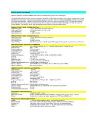
<strong>DE285</strong> <strong>HD</strong> <strong>Caption</strong> <strong>Decoder</strong>/<strong>VANC</strong> <strong>Monitor</strong>Appendix CVideo/Connector Specifications<strong>HD</strong>–SDI Video InputsNumber of Inputs 1 (Program In relay bypass protected)Connector BNC per IEC 169–8Format 1.485 Gbits/s SMPTE 292M (1080i, 720p, 480p,24psf) or 270 Mb/s SDInput Level 800 mV p–p ± 10%Input Impedance 75 OhmEqualizationAutomatic up to 100m @ 1.5Gb/s with Belden1694 or equivalent<strong>HD</strong>–SDI Video OutputsNumber of Outputs 2 (Program Out 1 relay bypass protected)Connector BNC per IEC 169–8Output Level 800 mV p–p ± 10%Output Impedance 75 OhmDC Offset 0V ± 0.5VRise/Fall Time 200pS nominalOvershoot< 10% of amplitudeWide Band Jitter < 0.2 UIData Input CharacteristicsData PortsGPI/GPOSerial Data FormatUSB PortsLANElectricalPowerPower ConsumptionPhysicalDimensionsWeight2 serial DB9 female connectors25–pin GPIO(TEST, for factory use only)1 USB master (TEST, for factory use only)2 USB slaveRJ45 connector, 10/100 Base T TCP/IP115/230V AC 50/60Hz< 20 W19” rack mount x 1RU x 9” deep8 lbs.42 Copyright ©2009-2011 <strong>EEG</strong> <strong>Enterprises</strong>, Inc.All rights reserved.
<strong>DE285</strong> <strong>HD</strong> <strong>Caption</strong> <strong>Decoder</strong>/<strong>VANC</strong> <strong>Monitor</strong>Appendix DBinary ANC Dump Data FormatTo view the ANC capture that you have saved to your USB stick, firstopen the file in a hex editor and then view the data format chart below.Description SizeDIDSDIDData CountDataChecksumFrame Number1 byte1 byte1 bytespecified by Data Count1 byte1 byteANC Line Number 2 bytesThe ANC Line Number is little endian. If the most significant bit is set,the packet came from HANC; if not it came from <strong>VANC</strong>.The Frame Number is a 1 byte counter generated internally to the <strong>DE285</strong>that will allow you to determine frame barriers or gaps when looking atseries of packets.Copyright ©2009-2011 <strong>EEG</strong> <strong>Enterprises</strong>, Inc.All rights reserved.43