Vectra Genisys Service Manual - DJO Global
Vectra Genisys Service Manual - DJO Global
Vectra Genisys Service Manual - DJO Global
- No tags were found...

You also want an ePaper? Increase the reach of your titles
YUMPU automatically turns print PDFs into web optimized ePapers that Google loves.
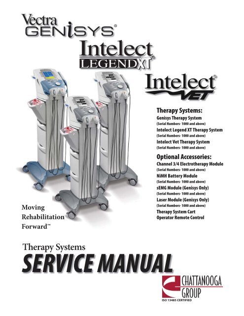
®MovingRehabilitationForwardTherapy Systems:<strong>Genisys</strong> Therapy System(Serial Numbers- 1000 and above)Intelect Legend XT Therapy System(Serial Numbers- 1000 and above)Intelect Vet Therapy System(Serial Numbers- 1000 and above)Optional Accessories:Channel 3/4 Electrotherapy Module(Serial Numbers- 1000 and above)NiMH Battery Module(Serial Numbers- 1000 and above)sEMG Module (<strong>Genisys</strong> Only)(Serial Numbers- 1000 and above)Laser Module (<strong>Genisys</strong> Only)(Serial Numbers- 1000 and above)Therapy System CartOperator Remote ControlTherapy SystemsSERVICE MANUALISO 13485 CERTIFIED
FOREWORD<strong>Vectra</strong> <strong>Genisys</strong>®/Intelect Legend XT®/ Intelect® Vet Therapy SystemsRead, understand, and follow the Safety Precautions and all other information contained in thismanual.This manual contains the necessary safety and field service information for those field servicetechnicians, certified by Chattanooga Group, to perform field service on the <strong>Vectra</strong> <strong>Genisys</strong>, IntelectLegend XT and Intelect Vet Therapy Systems, modules, and accessories.At the time of publication, the information contained herein was current and up-to-date. However,due to continual technological improvements and increased clinical knowledge in the field ofelectrotherapy, ultrasound, Iontophoresis, and Laser therapy, as well as Chattanooga Group’s policyof continual improvement, Chattanooga Group reserves the right to make periodic changes andimprovements to their equipment and documentation without any obligation on the part ofChattanooga Group.It is the sole responsibility for certified field service technicians to stay informed and trained in thelatest technology utilized in the <strong>Vectra</strong> <strong>Genisys</strong>, Intelect Legend XT and Intelect Vet Therapy Systemsby Chattanooga Group. From time to time, as significant improvements are incorporated, servicebulletins will be produced and made available on our web site (chattgroup.com) in lieu of reprintinga complete manual prematurely. These service bulletins will provide updated service informationand technological improvements to the <strong>Vectra</strong> <strong>Genisys</strong>, Intelect Legend XT and Intelect Vet TherapySystems for use by certified service technicians.Due to the complex nature of the technology utilized by Chattanooga Group, the recommendedtroubleshooting techniques are to determine “Bad Board” and board replacement only. No boardcomponent level troubleshooting is recommended, nor will information or parts be supplied byChattanooga Group.Any board component level troubleshooting performed will be at the sole risk and liability of thecertified field service technician performing such troubleshooting techniques. Performance of suchtechniques may render the warranty null and void.The <strong>Vectra</strong> <strong>Genisys</strong> and Intelect Legend XT equipment is to be used only under theprescription and supervision of a licensed medical practitioner.The Intelect Vet is to be used only under the prescription and supervision of a licensedveterinarian.©2008 Encore Medical, L.P. and its affiliates, Austin, Texas, USA. Any use of editorial, pictorial, or layout composition of this publication without express written consent fromChattanooga Group of Encore Medical, L.P. is strictly prohibited. This publication was written, illustrated, and prepared for distribution by Chattanooga Group of Encore Medical, L.P.1
1- THEORY OF OPERATION<strong>Vectra</strong> <strong>Genisys</strong>®/Intelect Legend XT®/ Intelect® Vet Therapy Systems1.1 OVERVIEWThe <strong>Vectra</strong> <strong>Genisys</strong>, Intelect Legend XT and Intelect Vet Therapy Systems are comprised of several PC boardassemblies housed within a common enclosure. These assemblies each support a distinct function inthe product. The basic elements are User Interface, Control Board, Stim Board, Ultrasound Board, UltrasoundApplicator, and Power Supply Circuits.When a Module (Channel 3/4 Electrotherapy, NiMH Battery, Laser, or sEMG) is installed, the Control Boardsoftware automatically recognizes that a Module has been installed and prompts the installer to performcertain tasks, for verification of Module installed, to make the respective Module fully functional. No additionalsoftware installation is required as the Therapy System contains all necessary software to accommodate anyModule installation.1.2 POWER SUPPLY CIRCUITSA universal input 100 Watt power supply provides the Control Board and Stim Board of the system with 24volts DC. The supply is connected to the mains at all times when the cord is attached. The 24 VDC supply isregulated locally at each PC board as required. On Combination Systems, a separate universal 75 Watt PowerSupply provides 24 volts DC to the Ultrasound PC Board. The 24 volt DC power is regulated at the board, asrequired.1.3 CONTROL BOARDThe Control Board serves just as its name implies. It controls the operation of the stim board, ultrasoundboard, user interface, optional modules, and accessories. The control board communicates to the stimboards and ultrasound board through a proprietary bus. The control board drives the display. The controlboard reads the menu buttons. The control board also reads the amplitude and the contrast control (IntelectXT Only) systems. The control board reads and manages the Multimedia (MMC) Card, Patient Data Card,and sEMG Data Card. Sound output is generated by the control board and routed to an internal speaker.The control board reads the optional Patient Interrupt Switch and Operator Remote Control (used toadminister <strong>Manual</strong> Stimulation Therapy).1.4 STIM BOARDThe Stim Board creates all muscle stimulation output. Communications to the Stim Board is via aproprietary bus. A Processor on the Stim Board acts on messages passed to it by the Control Board toset up waveforms and adjust output amplitude. Information can likewise be passed from the StimBoard back to the Control Board for monitoring Current, Microcurrent Probe (<strong>Vectra</strong> <strong>Genisys</strong> andIntelect Legend XT only) Contact Quality indication, etc. If the Stim Board does not respond asexpected to a command from the Control Board, output is stopped and an Error Message is generated.1.5 ULTRASOUND BOARD AND APPLICATOR (COMBINATION SYSTEMS ONLY)The Ultrasound Board generates the 1 or 3.3 MHz output to drive the Sound Head of the Applicator. TheUltrasound Board is accessed through the proprietary bus by the Control Board. It can provide current andvoltage information about the ultrasound output of the board. The calibration data for the Sound Head ispassed through the Ultrasound Board from the Applicator to the Control Board. By storing the calibrationdata in the Applicator, there is no calibration necessary for the Ultrasound Board and any calibratedChattanooga Group <strong>Vectra</strong> <strong>Genisys</strong>, Intelect Legend XT, or Intelect Vet Ultrasound Applicator can beconnected and operated to provide accurate coupling and output.1.6 USER INTERFACE AND ACCESSORIESThe LCD display panel provides the operator visible feedback in the way of menu choices. Pressing of themenu buttons makes selections from the menus. The control board interprets these user inputs and respondsaccordingly. Audible feedback is given as well for events such as key presses and end of treatment.The control board accesses the Patient Data Card, sEMG Data Card and MMC Card via an on board Reader/Writer Interface. The voltage necessary to operate the reader is provided by the 100 Watt Power Supply and isregulated by the Control Board.A. Channel 3/4 Electrotherapy ModuleThe Channel 3/4 Electrotherapy Module creates all muscle stimulation output for Channels 3 and 4.The Channel 3/4 Electrotherapy Module is interfaced with the System via a ribbon cable whichsupplies power and facilitates communication between the stim board and control board of thesystem. All waveforms available to channels 1 and 2 are available to channels 3 and 4 via the systemsoftware. No additional software is required for full functionality of the module.2
1- THEORY OF OPERATION<strong>Vectra</strong> <strong>Genisys</strong>®/Intelect Legend XT®/ Intelect® Vet Therapy Systems1.6 USER INTERFACE AND ACCESSORIES (CONTINUED)B. NiMH Battery ModuleThe NiMH Battery Module incorporates two Nickel Metal Hydride (NiMH) Battery packs anda PC Board. The PC Board monitors the Charge Level of the Batteries. The Batteries supply 24 VDC tothe system which is then distributed to the respective pcb’s through the system power supply.The Battery Module is interfaced with the system via a ribbon cable that facilitates communicationwith the Control Board and delivery of power to a Two Channel Electrotherapy or CombinationTherapy System. When the Therapy System is connected to a Mains Power Supply via the PowerCord, the NiMH Battery Module will charge. Once the Module is fully charged the software will stopthe charging process eliminating the possibility of overcharging. Battery power is used only whenthe Therapy System is not connected to a Mains Power Supply.C. Laser Module and Applicators (<strong>Genisys</strong> and Intelect Vet Therapy Systems ONLY)The Laser Module utilizes a PC Board to communicate with the Control Board via a ribbon cable. TheLaser Module supplies the power required for each Laser Applicator through the Laser ApplicatorCable to PC Boards mounted within the Applicator housing. All Calibration Data for the Applicatorsis stored on board the respective Applicator. Each Applicator incorporates a lens that is instrumentalin delivery of the laser radiation to the patient. The Laser applicators are classified as Class 3BLaser products and are capable of up to 1440 nm of laser radiation in the infrared spectrum.Approved eye protection must be worn by all persons in the vicinity when the Laser is on. TheTherapy System incorporates and demands entry of a unique PIN before operation of the LaserApplicators is allowed by the Therapy System. The Module also incorporates a Therapy Room DoorLockout Jack to accommodate a lockout switch that would prevent operation of the LaserApplicators should the lockout safety device be breached by persons entering or exiting the therapyroom. Purchase and installation of the Lockout Device is the responsibility of the facility or clinic.D. sEMG Module (<strong>Genisys</strong> Therapy Systems ONLY)The Surface Electromyography (sEMG) Module utilizes a PC board to communicate to the Stim andControl Boards via direct PC Board Contacts. The sEMG module reads and transmits muscle activitythrough lead wires and electrodes. The sEMG Module communicates muscle activity data to the ControlBoard which can store the data on an sEMG Data Card via the on board Card Reader/Writer for viewing ona PC in graph form via the optional Chattanooga Group Patient Data Management System (PDMS)Software and Card Reader.E. Operator Remote ControlThe Operator Remote Control is just as its name indicates and incorporates a PC Board. The Channel 1/2Operator Remote Control is interfaced with the Therapy System through its unique connector on thefront of the Therapy System and the Channel 3/4 Electrotherapy Module. The Operator Remote Controlcommunicates with the Stim Board(s) to the Control Board for the administration of <strong>Manual</strong> Stim Therapyonly.F. Therapy System CartThe Therapy System Cart is designed for use with the Chattanooga Group Therapy Systems only. Thecart alone provides mobility to the Therapy System and storage of necessary accessories and suppliesused in conjunction with the Therapy System.3
2- SAFETY PRECAUTIONS2.1 PRECAUTIONARY DEFINITIONSThe precautionary instructions found in thissection and throughout this manual are indicatedby specific symbols. Understand these symbolsand their definitions before operating thisequipment. The definition of these symbols are asfollows:CautionCorrosive<strong>Vectra</strong> <strong>Genisys</strong>®/Intelect Legend XT®/ Intelect® Vet Therapy SystemsText with a “CORROSIVE" indicator will explainpossible safety infractions if the chemicalcomponents of the battery are exposed to air,skin, or other materials.Laser Eye ProtectionText with a “CAUTION” indicator will explainpossible safety infractions that could have thepotential to cause minor to moderate injury ordamage to equipment.WarningText with a “WARNING” indicator will explainpossible safety infractions that will potentiallycause serious injury and equipment damage.Text with a “LASER EYE PROTECTION" indicatorwill explain possible safety infractions that couldcause serious eye injury or blindness if the eyesare directly or reflectively exposed to LaserRadiation.Spontaneous CombustionDangerText with a “DANGER” indicator will explainpossible safety infractions that are imminentlyhazardous situations that would result in deathor serious injury.Dangerous VoltageText with a “SPONTANEOUS COMBUSTION"indicator will explain possible safety infractionsthat could create conditions for a SpontaneousCombustion if the material is mishandled andnot disposed of properly.Biohazardous MaterialsText with a “DANGEROUS VOLTAGE” indicatorserves to inform the technician of possiblehazards resulting in the electrical chargedisbursement from certain components ifhandled or serviced improperly.Text with a “BIOHAZARD” indicator serves toinform the user of possible hazards resultingin improper handling of components andaccessories that have come in contact withbodily fluids.Non-Ionizing Electromagnetic RadiationLaserText with a “LASER" indicator will explainpossible safety infractions that are imminentlyhazardous situations that would result seriousinjury to eyes or blindness.4Text with a “NON-IONIZING ELECTROMAGNETICRADIATION" indicator informs the user ofpossible hazards resulting from elevated,potentially dangerous, levels of non-ionizingradiation.NoteThroughout this manual “NOTE” may be found.These Notes are helpful information to aid inthe particular area or function being described.
2- SAFETY PRECAUTIONS<strong>Vectra</strong> <strong>Genisys</strong>®/Intelect Legend XT®/ Intelect® Vet Therapy Systems2.2 PRECAUTIONARY INSTRUCTIONS• Read, understand, and practice the precautionary andoperating instructions. Know the limitations and hazardsassociated with using any laser device. Observe theprecautionary and operational decals placed on the unit.• Do not operate this unit when connected to any unit otherthan Chattanooga Group devices.• Do not operate this unit in an environment whereother devices are being used that intentionally radiateelectromagnetic energy in an unshielded manner. Portableand mobile RF communications equipment can affectMedical Electrical Equipment.• The Laser System should be routinely checked beforeeach use to determine that all controls function normally;especially that the dosage control properly adjusts theintensity of the laser output in a stable manner. Also,determine that the treatment time control actually terminatesthe laser output when the timer reaches zero.• Ultrasound should be routinely checked before each use todetermine that all controls function normally, especially thatthe intensity control does properly adjust the intensity of theultrasonic power output in a stable manner. Also, determinethat the treatment time control does actually terminateultrasonic power output when the timer reaches zero.• DO NOT use sharp objects such as a pencil point or ballpointpen to operate the buttons on the control panel as damagemay result.• Use of controls or adjustments or performance of proceduresother than those specified herein may result in hazardousexposure to laser energy.• Handle all Applicators with care. Inappropriate handling ofthe Laser Applicator may adversely affect its characteristics.• Inspect Laser Applicator, Lenses, Cables, and associatedconnectors before each use. Do not use a damaged orotherwise compromised Laser Applicator.• This unit should be operated, transported and stored intemperatures between 59° F and 104° F (15° C and 40° C),with Relative Humidity ranging from 30%-60%.• Where the integrity of the external protective earth conductorarrangement is in doubt, equipment shall be operated fromits internal electrical power source.• DO NOT permit any foreign materials or liquids to enter theunit. Take care to prevent any foreign materials including, butnot limited to, inflammables, water, and metallic objects fromentering the unit. These may cause unit damage, malfunction,electrical shock, fire, or personal injury.• Before each use, inspect Ultrasound Applicator for cracks,which may allow the ingress of conductive fluid.• Inspect all cables and associated connectors beforeeach use.• This equipment generates, uses and can radiate radiofrequency energy and, if not installed and used inaccordance with the instructions, may cause harmfulinterference to other devices in the vicinity. However,there is no guarantee that interference will not occur ina particular installation. Harmful interference to otherdevices can be determined by turning this equipment onand off. Try to correct the interference using one or moreof the following: reorient or relocate the receiving device,increase the separation between the equipment, connectthe equipment to an outlet on a different circuit from thatto which the other device(s) are connected and consult thefactory field service technician for help.• The <strong>Vectra</strong> <strong>Genisys</strong> Therapy System, the Intelect Legend XTTherapy System and the Intelect Vet Therapy System are notdesigned to prevent the ingress of water or liquids. Ingressof water or liquids could cause malfunction of internalcomponents of the system and therefore create a risk ofinjury to the patient.• Nylatex® Wraps contain dry natural rubber and may causeallergic reactions in patients with allergies to latex.• Use of parts or materials other than Chattanooga Group'scan degrade minimum safety.• U.S.A. Federal Law restricts these devices to sale by, or onthe order of, a physician or licensed practitioner. This deviceshould be used only under the continued supervision of aphysician or licensed practitioner.• Make certain the unit is electrically grounded by connectingonly to a grounded electrical service receptacle conformingto the applicable national and local electrical codes.• This device should be kept away from children.• Care must be taken when operating this equipment aroundother equipment. Potential electromagnetic or otherinterference could occur to this or to the other equipment.Try to minimize this interference by not using otherequipment in conjunction with it.• This equipment is not designed to prevent the ingress of wateror liquids. Ingress of water or liquids could cause malfunctionof internal components of the system and therefore create arisk of injury to the patient.• Do not drop the applicator or unit on hard surfaces. Do notcool an overheated applicator with ice water or ice packs. Donot allow the applicator to reach maximum temperaturesrepeatedly. Do not submerge the applicator or unit in water.All of these conditions will damage the applicator and unit.Damage resulting from these conditions is not covered underthe warranty.• The safety of TENS waveforms for use during pregnancy orbirth has not been established.• TENS is not effective for pain of central origin. (This includesheadache.)• TENS should be used only under the continued supervisionof a physician or licensed practitioner.• TENS waveforms have no curative value.• TENS is a symptomatic treatment, and as such, suppressesthe sensation of pain which would otherwise serve as aprotective mechanism.• Electronic monitoring equipment (such as ECG monitorsand ECG alarms) may not operate properly when TENSstimulation is in use.• In the event that an Error message or Warning appearsbeginning with a 2 or 3, immediately stop all use of thesystem and contact the dealer or Chattanooga Group forservice. Errors and Warnings in these categories indicate aninternal problem with the system that must be tested byChattanooga Group or a Field <strong>Service</strong> Technician certifiedby Chattanooga Group before any further operation oruse of the system. Use of a system that indicates an Erroror Warning in these categories may pose a risk of injury tothe patient, user or cause extensive internal damage to thesystem.5
2- SAFETY PRECAUTIONS2.2 PRECAUTIONARY INSTRUCTIONS (CONTINUED)<strong>Vectra</strong> <strong>Genisys</strong>®/Intelect Legend XT®/ Intelect® Vet Therapy Systems• Use of controls or adjustments or performance ofprocedures other than those specified herein may result inhazardous exposure to ultrasonic energy.• Before administering any treatment to a patient you shouldbecome acquainted with the operating procedures foreach mode of treatment available, as well as the indications,contraindications, warnings and precautions. Consultother resources for additional information regarding theapplication of Electrotherapy and Ultrasound.• To prevent electrical shock, disconnect the unit fromthe power source before attempting any maintenanceprocedures.• Keep electrodes separated during treatment. Electrodes incontact with each other could result in improper stimulationor skin burns.• Long term effects of chronic electrical stimulation areunknown.• Stimulation should not be applied over the anterior neckor mouth. Severe spasm of the laryngeal and pharyngealmuscles may occur and the contractions may be strongenough to close the airway or cause difficulty in breathing.• Stimulation should not be applied transthoracically in thatthe introduction of electrical current into the heart maycause cardiac arrhythmia.• Stimulation should not be applied over swollen, infected,and inflamed areas or skin eruptions, e.g., phlebitis,thrombophlebitis, varicose veins, etc.• Stimulation should not be applied over, or in proximity to,cancerous lesions.• Output current density is related to electrode size. Improperapplication may result in patient injury. If any questionarises as to the proper electrode size, consult a licensedpractitioner prior to therapy session.• The <strong>Vectra</strong> <strong>Genisys</strong> Therapy System optional modules andassociated accessories are designed for use only with theChattanooga Group <strong>Vectra</strong> <strong>Genisys</strong> Electrotherapy andCombination Therapy Systems.• Remove the Ultrasound or Laser Applicator by pulling thecable connector only. DO NOT remove by pulling the cable.• Stimulus delivered by the TENS waveforms of thisdevice, in certain configurations, will deliver a charge of25 microcoulombs (μC) or greater per pulse and maybe sufficient to cause electrocution. Electrical currentof this magnitude must not flow through the thoraxbecause it may cause a cardiac arrhythmia.• Patients with an implanted neurostimulation devicemust not be treated with or be in close proximity toany shortwave diathermy, microwave diathermy,therapeutic ultrasound diathermy or laser diathermyanywhere on their body. Energy from diathermy(shortwave, microwave, ultrasound and laser) can betransferred through the implanted neurostimulationsystem, can cause tissue damage, and can result insevere injury or death. Injury, damage or death canoccur during diathermy therapy even if the implantedneurostimulation system is turned “off.”• Handle, clean and dispose of components andaccessories that have come in contact with bodilyfluids according to National, Local and Facility rules,regulations and procedures.• DO NOT connect the unit to an electrical supply withoutfirst verifying that the power supply is the correctvoltage. Incorrect voltage may cause unit damage,malfunction, electrical shock, fire, or personal injury. Yourunit was constructed to operate only on the electricalvoltage specified on the Voltage Rating and SerialNumber Plate. Contact your dealer if the unit is notproperly rated.• When the unit is on, not all wavelengths are visibleto the naked eye. Therefore, when performing anyoperational or functional check, make certain all personsin the vicinity of the laser wear Chattanooga Group laserprotective eyewear.• DO NOT point the laser beam directly into human oranimal eyes. The lens of the eye does not detect theinvisible, coherent laser beams, potentially resulting inpermanent retinal damage.• Class 3B Lasers are considered an acute hazard to theskin and eyes from direct radiation. Eye injury will occuris laser is viewed directly or from specular frelection. Eyeprotection is required for all persons in the treatmentarea.• Power Supplies retain High Voltage!• NiMH batteries contain Class E corrosive materials. In theevent of battery cell rupture or leakage, handle batterymodule wearing neoprene or natural rubber gloves.Contents of a ruptured or leaking battery can causerespiratory irritation. Hypersensitivity to nickel can causeallergic pulmonary asthma. Contents of cell coming incontact with skin can cause skin irritation and chemicalburns.• Never, under any circumstances, open the batterycells. Should an individual cell from a battery becomedisassembled, spontaneous combustion of the negativeelectrode is possible. There can be a delay betweenexposure to air and spontaneous combustion.• Charge the Battery Module according to theinstructions found in this manual. Never attempt tocharge the Battery Module on any other chargingmechanism.• Use the Battery Module only with the <strong>Vectra</strong> <strong>Genisys</strong>Therapy Systems.• Do not reverse the polarity of the Battery Module. Doingso can increase the individual cell temperature andcause cell rupture or leakage.• Never dispose of Battery Module in fire. Never shortcircuit the battery. The battery may explode, ignite, leakor get hot causing serious personal injury.• Dispose of NiMH batteries according to national, stateand local codes and regulations.6
3- NOMENCLATURE<strong>Vectra</strong> <strong>Genisys</strong>®/Intelect Legend XT®/ Intelect® Vet Therapy Systems3.1 VECTRA GENISYS, INTELECT LEGEND XT AND INTELECT VET THERAPY SYSTEMSA. <strong>Vectra</strong> <strong>Genisys</strong>, Intelect Legend XT and Intelect Vet Therapy SystemsThe nomenclature graphic below, Figure 3.1,locates the major components of an <strong>Vectra</strong><strong>Genisys</strong>, Intelect Legend XT and Intelect Vettwo channel combination therapy systemequipped with the following: Channel 3/4Electrotherapy Module, *sEMG Module, andTherapy System Cart.Refer to the respective pages of this sectionfor specific nomenclature of the optionalmodules.* <strong>Genisys</strong> Therapy Systems ONLYTWO CHANNEL COMBINATION THERAPY SYSTEMREFER TO PAGE 8TWO CHANNEL ELECTROTHERAPY SYSTEMREFER TO PAGE 9ULTRASOUND APPLICATORDUAL CHANNEL SEMG MODULE*REFER TO PAGE 14(INSTALLED TO BOTTOM OF THERAPY SYSTEM)CHANNEL 3/4 ELECTROTHERAPY MODULEREFER TO PAGE 10ORNIMH BATTERY MODULEREFER TO PAGE 11ORLASER MODULE & APPLICATORS*REFER TO PAGES 12 AND 13CHANNELS 1/2 AND 3/4 OPERATOR REMOTEREFER TO PAGE 16THERAPY SYSTEM CARTREFER TO PAGE 15FIGURE 3.17
3- NOMENCLATURE<strong>Vectra</strong> <strong>Genisys</strong>®/Intelect Legend XT®/ Intelect® Vet Therapy Systems3.1 VECTRA GENISYS, INTELECT LEGEND XT AND INTELECT VET THERAPY SYSTEMS (CONTINUED)B. <strong>Vectra</strong> <strong>Genisys</strong>, Intelect Legend XT and Intelect Vet Combination Therapy SystemsThe nomenclature graphics below, Figure 3.2,indicate the general locations of the exteriorcomponents of the Two Channel <strong>Vectra</strong> <strong>Genisys</strong>,Intelect Legend XT or the Intelect VetCombination Therapy Systems.111Know the components and their functionsbefore performing any operation of or serviceto the <strong>Vectra</strong> <strong>Genisys</strong>, Intelect Legend XT or theIntelect Vet Two Channel Combination TherapySystems.6832745109191.2.3.4.5.6.7.8.9.10.Screen Contrast Control (Not functional on colorSystems)System Power On/Off SwitchTechnical Maintenance PortMain Power CordRear Access PanelTwo Channel Combo SystemUltrasound Applicator (5cm 2 shown) ComboSystems OnlyUser Interface (Screen and Buttons)Front Access PanelPatient Data Card and sEMG Data Card access portFIGURE 3.211.12.13.14.15.16.17.18.19.12 13Multimedia Card (MMC) access portFront Access Panel Lanyard- When reinstalling theFront Access Panel, make certain the Lanyard doesnot become kinkedChannel 1/2 Operator Remote Control ConnectorPatient Interrupt Switch ConnectorChannel 1 Lead Wire ConnectorChannel 2 Lead Wire ConnectorMicrocurrent Probe ConnectorUltrasound Applicator ConnectorTherapy System to Module Ribbon Cable(not shown)14151617188
3- NOMENCLATURE<strong>Vectra</strong> <strong>Genisys</strong>®/Intelect Legend XT®/ Intelect® Vet Therapy Systems3.1 VECTRA GENISYS, INTELECT LEGEND XT AND INTELECT VET THERAPY SYSTEMS (CONTINUED)C. <strong>Vectra</strong> <strong>Genisys</strong>, Intelect Legend XT and Intelect Vet Electrotherapy SystemsThe nomenclature graphics below, Figure 3.3,indicate the general locations of the exteriorcomponents of the Two Channel <strong>Vectra</strong> <strong>Genisys</strong>,Intelect Legend XT or the Intelect Vet TwoChannel Electrotherapy Systems.Know the components and their functionsbefore performing any operation of or serviceto the <strong>Vectra</strong> <strong>Genisys</strong>, Intelect Legend XT orthe Intelect Vet Two Channel ElectrotherapySystems.16327451098171.2.3.4.5.6.7.8.9.Screen Contrast Control (Not functional on ColorSystems)System Power On/Off SwitchTechnical Maintenance PortMain Power CordRear Access PanelTwo Channel Electrotherapy SystemUser Interface (Screen and Buttons)Front Access PanelPatient Data Card and sEMG Data Card accessportFIGURE 3.310.11.12.13.14.15.16.17.1112Multimedia Card (MMC) access portFront Access Panel Lanyard- When reinstallingthe Front Access Panel, make certain the Lanyarddoes not become kinkedChannel 1/2 Operator Remote Control ConnectorPatient Interrupt Switch ConnectorChannel 1 Lead Wire ConnectorChannel 2 Lead Wire ConnectorMicrocurrent Probe ConnectorTherapy System to Module Ribbon Cable(not shown)131415169
3- NOMENCLATURE<strong>Vectra</strong> <strong>Genisys</strong>®/Intelect Legend XT®/ Intelect® Vet Therapy Systems3.1 VECTRA GENISYS, INTELECT LEGEND XT AND INTELECT VET THERAPY SYSTEMS (CONTINUED)D. <strong>Vectra</strong> <strong>Genisys</strong>, Intelect Legend XT and Intelect Vet Channel 3/4 Electrotherapy ModuleThe nomenclature graphics below, Figure 3.4,indicate the general locations of the exteriorcomponents of the <strong>Vectra</strong> <strong>Genisys</strong>, IntelectLegend XT and Intelect Vet Therapy SystemsChannel 3/4 Electrotherapy Module.Know the components and their functionsbefore performing any operation of or serviceto the <strong>Vectra</strong> <strong>Genisys</strong>, Intelect Legend XT andIntelect Vet Therapy Systems Channel 3/4Electrotherapy Module.6512437891011FIGURE 3.41. Two (2) Channel Electrotherapy Module2. Extended Front Access Panel3. Module to System Mounting Holes4. Module to System Feet Alignment Indents5. Power Cord Routing Port6. Module to System Connector7. Operator Remote Control Connector8. Patient Interrupt Switch Connector9. Channel 3 Lead Wire Connector10. Channel 4 Lead Wire Connector11. Microcurrent Probe ConnectorAlso Included:• Four 4mm X 20mm mounting screws• Channel 3 and 4 Lead Wires• Sample of Dura-Stick II electrodesNOTE:The Channel 3/4 Electrotherapy Module is notoperable unless it is properly connected to a <strong>Vectra</strong><strong>Genisys</strong>, Intelect Legend XT or an Intelect Vet TherapySystem.10
3- NOMENCLATURE<strong>Vectra</strong> <strong>Genisys</strong>®/Intelect Legend XT®/ Intelect® Vet Therapy Systems3.1 VECTRA GENISYS, INTELECT LEGEND XT AND INTELECT VET THERAPY SYSTEMS (CONTINUED)E. <strong>Vectra</strong> <strong>Genisys</strong>, Intelect Legend XT and Intelect Vet NiMH Battery ModuleThe nomenclature graphic below, Figure 3.5,indicates the general locations of the exteriorcomponents of the <strong>Vectra</strong> <strong>Genisys</strong>, IntelectLegend XT and Intelect Vet Systems NiMHBattery Module.Know the components and their functionsbefore performing any operation of or serviceto the <strong>Vectra</strong> <strong>Genisys</strong>, Intelect Legend XT andIntelect Vet Therapy Systems NiMH BatteryModule.651243FIGURE 3.51. NiMH Battery Module2. Extended Front Access Panel3. Module to System Mounting Holes4. Module to System Feet Alignment Indents5. Power Cord Routing Port6. Module to System ConnectorNOTE:The NiMH Battery Module is not operable unless itis properly connected to an <strong>Vectra</strong> <strong>Genisys</strong>, IntelectLegend XT, or Intelect Vet Therapy System.11
3- NOMENCLATURE<strong>Vectra</strong> <strong>Genisys</strong>®/Intelect Legend XT®/ Intelect® Vet Therapy Systems3.1 VECTRA GENISYS, INTELECT LEGEND XT AND INTELECT VET THERAPY SYSTEMS (CONTINUED)F. <strong>Vectra</strong> <strong>Genisys</strong> and Intelect Vet Laser ModuleThe nomenclature graphic below, Figure 3.6,indicates the general locations of the exteriorcomponents of the <strong>Vectra</strong> <strong>Genisys</strong> and IntelectVet Therapy System Laser Module.Know the components and their functionsbefore performing any operation of or service tothe Therapy System Laser Module.6512437 8 9 10FIGURE 3.61. Laser Module2. Extended Front Access Panel3. Module to System Mounting Holes4. Module to System Feet Alignment Indents5. Power Cord Routing Port6. Module to System Header7. Patient Interrupt Switch (Optional)8. Therapy Room Door Lockout Jack9. Point Locator (for use with Single Applicator LaserApplicators)10. Laser ApplicatorNOTE:The Laser Module is not operable unless it is properlyconnected only to its Therapy System.NOTE:No Field <strong>Service</strong> is applicable to the Laser Module orLaser Applicators. All Laser Modules and Applicatorssuspected to require service or calibration must besent to the factory.• DO NOT point the laser beam directly intohuman or animal eyes. The lens of the eyedoes not detect the invisible, coherent laserbeams, potentially resulting in permanentretinal damage.• Class 3B Lasers are considered an acute hazardto the skin and eyes from direct radiation.Eye injury will occur if laser is viewed directlyor from specular reflection. Laser protectiveeyewear is required for all persons in thetreatment area.• Approved Laser protective eyewear must beworn at all times by all persons in the vicinitywhen the Laser is On.12
3- NOMENCLATURE<strong>Vectra</strong> <strong>Genisys</strong>®/Intelect Legend XT®/ Intelect® Vet Therapy Systems3.1 VECTRA GENISYS, INTELECT LEGEND XT AND INTELECT VET THERAPY SYSTEMS (CONTINUED)G. <strong>Vectra</strong> <strong>Genisys</strong> and Intelect Vet Laser ApplicatorsThe nomenclature graphics below, Figure 3.7,indicate the general locations of the exteriorcomponents of the <strong>Vectra</strong> <strong>Genisys</strong> and IntelectVet Therapy System Laser Applicators.1Know the components and their functionsbefore performing any operation of or serviceto the <strong>Vectra</strong> <strong>Genisys</strong> and Intelect Vet TherapySystem Laser Therapy System Laser Applicators.7237616241256NOTE:No Field <strong>Service</strong> is applicable to the Laser Module or Laser Applicators. All LaserModules and Applicators suspected to require service or calibration must be sentto the factory.71.2.3.4.5.6.Laser On LEDLaser Applicator On/Off ButtonSingle Diode Applicator HousingLED Cluster Applicator HousingLaser Cluster Applicator HousingLaser Aperture LensLaser Aperture7.NOTE:The Laser Applicators are not operable unless they areconnected to its Therapy Systems only via the LaserModule.No Field <strong>Service</strong> is applicable to the Laser Module orLaser Applicators. All Laser Modules and Applicatorssuspected to require service or calibration must besent to the factory.FIGURE 3.7• DO NOT point the laser beam directly intohuman or animal eyes. The lens of the eyedoes not detect the invisible, coherent laserbeams, potentially resulting in permanentretinal damage.• Class 3B Lasers are considered an acute hazardto the skin and eyes from direct radiation.Eye injury will occur if laser is viewed directlyor from specular reflection. Laser protectiveeyewear is required for all persons in thetreatment area.• Approved Laser protective eyewear must beworn at all times by all persons in the vicinitywhen the Laser is On.13
3- NOMENCLATURE<strong>Vectra</strong> <strong>Genisys</strong>®/Intelect Legend XT®/ Intelect® Vet Therapy Systems3.1 VECTRA GENISYS, INTELECT LEGEND XT AND INTELECT VET THERAPY SYSTEMS (CONTINUED)H. <strong>Vectra</strong> <strong>Genisys</strong> Dual Channel sEMG ModuleThe nomenclature graphics below, Figure 3.8,indicate the general locations of the exteriorcomponents of the <strong>Vectra</strong> <strong>Genisys</strong> TherapySystem Dual Channel sEMG Module.Know the components and their functionsbefore performing any operation of or service tothe <strong>Vectra</strong> <strong>Genisys</strong> Therapy System Dual ChannelsEMG Module.134265FIGURE 3.81. sEMG Module Top Housing2. Module Removal Slot3. Module to System Mounting Tabs4. Module to System PC Board Contacts5. Module to System Retaining Tab6. sEMG Module Bottom HousingNOTE:The <strong>Vectra</strong> <strong>Genisys</strong> Dual Channel sEMG Module is notoperable unless it is connected to the <strong>Vectra</strong> <strong>Genisys</strong>Therapy System.14
3- NOMENCLATURE<strong>Vectra</strong> <strong>Genisys</strong>®/Intelect Legend XT®/ Intelect® Vet Therapy Systems3.1 VECTRA GENISYS, INTELECT LEGEND XT AND INTELECT VET THERAPY SYSTEMS (CONTINUED)I. <strong>Vectra</strong> <strong>Genisys</strong>, Intelect Legend XT and Intelect Vet Therapy System CartThe nomenclature graphics below, Figure 3.9,indicate the general locations of the exteriorcomponents of the <strong>Vectra</strong> <strong>Genisys</strong>, IntelectLegend XT and Intelect Vet TherapySystems Cart.Know the components and their functions beforeperforming any operation of or service to the<strong>Vectra</strong> <strong>Genisys</strong>, Intelect Legend XT and IntelectVet Therapy Systems Cart.132485671. Cart Top2. System to Cart Retaining Screw (4)3. Storage Bins (6)4. Cart Rear Swivel Casters5. Cart Base6. Cart Front Swivel, Locking Casters7. Cart Bottom Access Plate8. Front and Rear Cart ExtrusionsFIGURE 3.915
3- NOMENCLATURE<strong>Vectra</strong> <strong>Genisys</strong>®/Intelect Legend XT®/ Intelect® Vet Therapy Systems3.1 VECTRA GENISYS, INTELECT LEGEND XT AND INTELECT VET THERAPY SYSTEMS (CONTINUED)J. <strong>Vectra</strong> <strong>Genisys</strong>, Intelect Legend XT and Intelect Vet Operator Remote ControlThe nomenclature graphics below, Figure 3.10,Know the components and their functionsindicate the general locations of the exteriorbefore performing any operation of or servicecomponents of the <strong>Vectra</strong> <strong>Genisys</strong>, Intelectto the <strong>Vectra</strong> <strong>Genisys</strong>, Intelect Legend XT andLegend XT and Intelect Vet Therapy SystemsIntelect Vet Therapy Systems Operator RemoteOperator Remote Control.Control.71652*34* Blue button for Channels 1/2 Operator Remote ControlOrange button for Channels 3/4 Operator Remote ControlFIGURE 3.101. Operator Remote Storage Hook2. Treatment Pause Button3. Channel 2 Increase Intensity Button4. Channel 2 Decrease Intensity Button5. <strong>Manual</strong> Stimulation Button6. Channel 1 Decrease Intensity Button7. Channel 1 Increase Intensity ButtonNOTE:The <strong>Vectra</strong> <strong>Genisys</strong>, Intelect Legend XT, or Intelect VetOperator Remote Control is not operable unless it isproperly connected to the its Therapy System.Operator Remote Control Symbol DefinitionsINCREASEINTENSITYDECREASEINTENSITYMPAUSETREATMENTMANUALSTIMULATION16
3- NOMENCLATURE<strong>Vectra</strong> <strong>Genisys</strong>®/Intelect Legend XT®/ Intelect® Vet Therapy Systems3.2 VECTRA GENISYS, INTELECT LEGEND XT AND INTELECT VET THERAPY SYSTEMS HARDWAREAND SOFTWARE SYMBOL DEFINITIONSThe symbol graphics below are found on thesystem as well as within the software. Thesesymbols are defined below for the purpose ofrecognition and functionality when operatingor performing service on an <strong>Vectra</strong> <strong>Genisys</strong>,Intelect Legend XT or Intelect Vet Therapy System,Modules, and Accessories.ON/OFFSWITCHDATAPORTMULTI-MEDIA ANDPATIENT CARDSTOPTREATMENTPAUSETREATMENTSTARTTREATMENTCHANNEL 1/2OPERATORREMOTECONTROL(OPTIONAL)PATIENTINTERRUPTSWITCH(OPTIONAL)CHANNEL 1LEAD WIRESCHANNEL 2LEAD WIRESKnow the symbols and their definitions beforeperforming any operation of or service to the<strong>Vectra</strong> <strong>Genisys</strong>, Intelect Legend XT or Intelect VetTherapy Systems, Modules, or Accessories.A. Hardware Symbols C. Optional Accessory SymbolsCONTRAST CONTROL(NOT FUNCTIONAL ONGENISYS SYSTEMS)CLINICALRESOURCESBACK1. Operator Remote Control SymbolsINCREASEINTENSITYDECREASEINTENSITY2. NiMH Battery Module SymbolsCHARGE LEVELMPAUSETREATMENTMANUALSTIMULATIONBATTERYCHARGING3. Channel 3/4 Electrotherapy Module SymbolsPATIENTINTERRUPTSWITCH(OPTIONAL)CHANNEL 3LEAD WIRESCHANNEL 4LEAD WIRESMICROCURRENTPROBE(INACTIVE ONINTELECT VET)CHANNEL 3/4OPERATORREMOTE|CONTROL(OPTIONAL)THERAPYINTENSITYCONTROLHOMEB. Software SymbolsMOVE UPMOVE DOWNMOVE RIGHTMICROCURRENTPROBE(INACTIVE ONINTELECT VET)ULTRASOUNDAPPLICATORMOVE LEFTACCEPT ANDRETURNDO NOT ACCEPTAND RETURN4. Laser Module Symbols (<strong>Genisys</strong> Only)PATIENTINTERRUPTSWITCH(OPTIONAL)TREATMENTROOM INTERLOCKCONNECTOR5. Laser Applicator Symbols (<strong>Genisys</strong> Only)PAUSETREATMENT6. Patient Interrupt SwitchPATIENTINTERRUPTSWITCH(OPTIONAL)POINTLOCATOR(INACTIVE)LASERAPPLICATOR17
4- SPECIFICATIONSThe specifications found in this section providephysical details of the <strong>Vectra</strong> <strong>Genisys</strong>, IntelectLegend XT and Intelect Vet Therapy Systems. Thissection also provides waveform specifications toaid in troubleshooting.A. Therapy Systems Physical Specifications<strong>Vectra</strong> <strong>Genisys</strong>®/Intelect Legend XT®/ Intelect® Vet Therapy Systems4.1 VECTRA GENISYS, INTELECT LEGEND XT AND INTELECT VET THERAPY SYSTEMSRefer to this section when performingtroubleshooting, replacement, and repair of a<strong>Vectra</strong> <strong>Genisys</strong>, Intelect Legend XT and Intelect VetTherapy System, Modules, and Accessories.HEIGHTCART ONLYHEIGHTWITH SYSTEM & SYSTEM WITH MODULEDEPTHWIDTHFIGURE 4.1DimensionsHeightCart Only . . . . . . . . . . . . . . . . . . . . . . . . . . . . . . . . . . . . . . . . . . . . . . . . . . . . . . . . . . . . . . . . . . . . . . . . . . . . . . . . . . . . . . . . 33.75 in (85.7 cm)With System . . . . . . . . . . . . . . . . . . . . . . . . . . . . . . . . . . . . . . . . . . . . . . . . . . . . . . . . . . . . . . . . . . . . . . . . . . . . . . . . . . . . . . 42.50 in (108 cm)With System and Module . . . . . . . . . . . . . . . . . . . . . . . . . . . . . . . . . . . . . . . . . . . . . . . . . . . . . . . . . . . . . . . . . . . . . . 44.25 in (112.4 cm)Width . . . . . . . . . . . . . . . . . . . . . . . . . . . . . . . . . . . . . . . . . . . . . . . . . . . . . . . . . . . . . . . . . . . . . . . . . . . . . . . . . . . . . . . . . . . . . . . . 17 in (43.2 cm)Depth . . . . . . . . . . . . . . . . . . . . . . . . . . . . . . . . . . . . . . . . . . . . . . . . . . . . . . . . . . . . . . . . . . . . . . . . . . . . . . . . . . . . . . . . . . . . . 16.25 in (41.3 cm)Power (Combination and Electrotherapy Systems)Input . . . . . . . . . . . . . . . . . . . . . . . . . . . . . . . . . . . . . . . . . . . . . . . . . . . . . . . . . . . . . . . . . . . . . . . . . . . . . 100 - 240 V - 175 VA, 50/60 HzOutput (Internal Power Supply) . . . . . . . . . . . . . . . . . . . . . . . . . . . . . . . . . . . . . . . . . . . . . . . . . . . . . . . . . . . . . . . . . . . . . . . .+24, 7.3 AElectrical Class . . . . . . . . . . . . . . . . . . . . . . . . . . . . . . . . . . . . . . . . . . . . . . . . . . . . . . . . . . . . . . . . . . . . . . . . . . . . . . . . . . . . . . . . . . . CLASS IMode of Operation . . . . . . . . . . . . . . . . . . . . . . . . . . . . . . . . . . . . . . . . . . . . . . . . . . . . . . . . . . . . . . . . . . . . . . . . . . . . . . . . . .ContinuousElectrical TypeUltrasound (Combination Systems Only) and Laser Module (<strong>Vectra</strong> <strong>Genisys</strong> and Intelect Vet Only) . . . . TYPE BElectrotherapy, sEMG and Channel 3/4 Module . . . . . . . . . . . . . . . . . . . . . . . . . . . . . . . . . . . . . . . . . . . . . . . . . . . . . . TYPE BF18
4- SPECIFICATIONS4.2 ELECTROTHERAPY WAVEFORM SPECIFICATIONSThe specifications found in this section providethe necessary waveform specifications to aid introubleshooting. A waveform graphic from anoscilloscope is also provided for clarification.Refer to this section when performingtroubleshooting, replacement, and repair of theTherapy System, Modules, and Accessories.A. IFC (Interferential) Traditional (4 Pole)-Figure 4.2 (<strong>Vectra</strong> <strong>Genisys</strong>, Intelect LegendXT, and Intelect Vet)Output Mode . . . . . . . . . . . . . . . . . . . . . . . ElectrodesOutput Intensity . . . . . . . . . . . . . . . . 0-100 mA(CC)0-100 V (CV)Carrier Frequency . . . .2,500, 4,000, and 5,000 HzBeat Frequency (Sweep Off ) . . . . . . . . . .1-200 HzSweep Time (Fixed) . . . . . . . . . . . . . . . . 15 secondsSweep Low Beat Frequency . . . . . . . . . .1-199 HzSweep High Beat Frequency . . . . . . . . . .2-200 HzVector Scan . . . . . . . Off, <strong>Manual</strong>, 40%, and 100%Treatment Time . . . . . . . . . . . . . . . . . . 1-60 MinutesMode Selection . . . . . . . . . . . . . . . . . . . . . CC or CV*(Intelect Vet Mode Selection Fixed- CV only)Available on Channels . . . . . .1 & 2, 3 & 4 Option<strong>Vectra</strong> <strong>Genisys</strong>®/Intelect Legend XT®/ Intelect® Vet Therapy SystemsNOTE:All waveforms, except High Voltage Pulsed Current(HVPC), of the <strong>Vectra</strong> <strong>Genisys</strong>, Intelect Legend XTand Intelect Vet Therapy Systems have a 200 mAcurrent limit.VMS, VMS Burst, and all TENS waveform outputintensities are measured, specified, and listed topeak, not peak to peak.All waveforms are available on all channels.FIGURE 4.2B. TENS- Asymmetrical Biphasic- Figure 4.3(<strong>Vectra</strong> <strong>Genisys</strong>)Output Mode . . . . . . . . . . . . . . . . . . . . . . . ElectrodesOutput Intensity . . . . . . . . . . . . . . . . 0-110 mA (CC)0-110 V (CV)Phase Duration . . . . . . . . . . . . . . . . . .20-1,000 μsecFrequency . . . . . . . . . . . . . . . . . . . . . . . . . . . .1-250 HzMode Selection . . . . . . . . . . . . . . . . . . . . . CC or CV*Burst Frequency . . . . . . . . . . . . . . . . . . . . . .0-10 bpsFrequency Modulation . . . . . . . . . . . . . . .0-250 HzAmplitude Modulation . . . . . . . . . .Off, 40%, 60%,80%, and 100%Cycle Time . . . . . . . . . . . . . . . . . . . .4/4, 4/8, 7/7, 5/5,4/12, 10/10, 10/20, 10/30, 10/50Treatment Time . . . . . . . . . . . . . . . . . . 1-60 minutesAvailable on Channels . . . . . .1 & 2, 3 & 4 Option*CC= Constant CurrentCV= Constant Voltage19FIGURE 4.3Stimulus delivered by the TENS waveforms of this device, in certainconfigurations, will deliver a charge of 25 microcoulombs (μC) orgreater per pulse and may be sufficient to cause electrocution.Electrical current of this magnitude must not flow through thethorax because it may cause a cardiac arrhythmia.
4- SPECIFICATIONS<strong>Vectra</strong> <strong>Genisys</strong>®/Intelect Legend XT®/ Intelect® Vet Therapy Systems4.2 ELECTROTHERAPY WAVEFORM SPECIFICATIONS (CONTINUED)C. TENS- Symmetrical Biphasic- Figure 4.4(<strong>Vectra</strong> <strong>Genisys</strong>, and Intelect Legend XT)Output Mode . . . . . . . . . . . . . . . . . . . . . . . ElectrodesOutput Intensity . . . . . . . . . . . . . . . . . 0-80 mA (CC)0-80 V (CV)Phase Duration . . . . . . . . . . . . . . . . . .20-1,000 μsecFrequency . . . . . . . . . . . . . . . . . . . . . . . . . . . .1-250 HzMode Selection . . . . . . . . . . . . . . . . . . . . . CC or CV*Burst Frequency . . . . . . . . . . . . . . . . . . . . . .0-10 bpsFrequency Modulation . . . . . . . . . . . . . . .0-250 HzAmplitude Modulation . . . . . . . . . .Off, 40%, 60%,80%, and 100%Cycle Time . . . . . . . . . . . . . . . . . . . .4/4, 4/8, 7/7, 5/5,4/12, 10/10, 10/20, 10/30, 10/50Treatment Time . . . . . . . . . . . . . . . . . . 1-60 minutesAvailable on Channels . . . . . .1 & 2, 3 & 4 OptionFIGURE 4.4D. High Voltage Pulsed Current (HVPC)-Figure 4.5 (<strong>Vectra</strong> <strong>Genisys</strong>, Intelect LegendXT, and Intelect Vet)Output Mode . . . . . . . . . . . . . . Electrodes or ProbeOutput Intensity . . . . . . . . . . . . . . . . . . . . . . . 0-500 VPolarity . . . . . . . . . . . . . . . . . . . Positive or NegativeRamp . . . . . . . . . . . . . . . . 0.5 sec, 1 sec, 2 sec, 5 secDisplay . . . . . . . . . . . . . . . . . . .Peak Current or VoltsSweep . . . . . . . . . . . . . . . . Continuous, 80/120 pps,1/120 pps, 1/10 ppsFrequency . . . . . . . . . . . . . . . . . . . . . . . . . . 10-120 HzCycle Time . . . . . . . . . . . . . . Continuous, 5/5, 4/12,10/10, 10/20, 10/30, 10/50Treatment Time . . . . . . . . . . . . . . . . . . 1-60 MinutesAnti-Fatique . . . . . . . . . . . . . . . . . . . . . . . . . Off or OnAvailable on Channels . . . . . .1 & 2, 3 & 4 OptionFIGURE 4.5*CC= Constant CurrentCV= Constant Voltage20
4- SPECIFICATIONS<strong>Vectra</strong> <strong>Genisys</strong>®/Intelect Legend XT®/ Intelect® Vet Therapy Systems4.2 ELECTROTHERAPY WAVEFORM SPECIFICATIONS (CONTINUED)E. VMS - Figure 4.6 (<strong>Vectra</strong> <strong>Genisys</strong>, andIntelect Vet)Output Mode . . . . . . . . . . . . . . . . . . . . . . . ElectrodesOutput Intensity . . . . . . . . . . . . . . . . . . . . .0-200 mA (CC)0-200 V (CV)Channel Mode . . . . Single, Reciprocal, Co-ContractPhase Duration . . . . . . . . . . . . . . . . . . . . . . . . 20-400 μsecMode Selection . . . . . . . . . . . . . . . . . . . . . . . . . CC or CV*Anti-Fatigue . . . . . . . . . . . . . . . . . . . . . . . . . . . . . . Off or OnSet Intensity . .Individual Channel Intensity Settingin Reciprocal and Co-Contract modesCycle Time . . . . . . . . . . . . . . . . . .Continuous, 5/5, 4/12,10/10, 10/20, 10/30, 10/50Frequency . . . . . . . . . . . . . . . . . . . . . . . . . . . . . . . 1-200 ppsRamp . . . . . . . . . . . . . 0.5 sec, 1 sec, 2 sec, and 5 secTreatment Time . . . . . . . . . . . . . . . . . . 1-60 minutesAvailable on Channels . . . . . .1 & 2, 3 & 4 OptionFIGURE 4.6F. IFC (Interferential) Premodulated (2p)-Figure 4.7 (<strong>Vectra</strong> <strong>Genisys</strong>, Intelect LegendXT and Intelect Vet)Output Mode . . . . . . . . . . . . . . . . . . . . . . . ElectrodesOutput Intensity . . . . . . . . . . . . . . . . 0-100 mA(CC)0-100 V (CV)Carrier Frequency (Fixed) . . . . . . . . . . . . . 2,500 HzBeat Frequency (Sweep Off ) . . . . . . . . . .1-200 HzSweep Time (Fixed) . . . . . . . . . . . . . . . . 15 secondsSweep Low Beat Frequency . . . . . . . . . .1-199 HzSweep High Beat Frequency . . . . . . . . . .2-200 HzVector Scan . . . . . . . Off, <strong>Manual</strong>, 40%, and 100%Treatment Time . . . . . . . . . . . . . . . . . . 1-60 MinutesMode Selection . . . . . . . . . . . . . . . . . . . . . CC or CV*(Intelect Vet Mode Selection Fixed- CC only)Available on Channels . . . . . .1 & 2, 3 & 4 OptionFIGURE 4.7*CC= Constant CurrentCV= Constant Voltage21
4- SPECIFICATIONS<strong>Vectra</strong> <strong>Genisys</strong>®/Intelect Legend XT®/ Intelect® Vet Therapy Systems4.2 ELECTROTHERAPY WAVEFORM SPECIFICATIONS (CONTINUED)G. Russian- Figure 4.8 (<strong>Vectra</strong> <strong>Genisys</strong>, IntelectLegend XT and Intelect Vet)Output Mode . . . . . . . . . . . . . . . . . . . . . . ElectrodesOutput Intensity . . . . . . . . . . . . . . . . . . . .0-100 mA (CC)0-100 V (CV)Carrier Frequency (Fixed) . . . . . . . . . . . . . 2,500 HzChannel Mode . . . . Single, Reciprocal, Co-ContractDuty Cycle . . . . . 10%, 20%, 30%, 40%, and 50%Mode Selection . . . . . . . . . . . . . . . . . . . . . . . . . CC or CV*(Intelect Vet Mode Selection Fixed- CC only)Anti-Fatigue . . . . . . . . . . . . . . . . . . . . . . . . . . . . . . Off or OnCycle Time . . . . . . . . . . . . . Continuous, 5/5, 4/12,10/10, 10/20, 10/30, 10/50Burst Frequency . . . . . . . . . . . . . . . . . . . 20-100 bpsRamp . . . . . . . . . . . . . . . . . 0.5, 1, 2, and 5 secondsTreatment Time . . . . . . . . . . . . . . . . . 1-60 minutesAvailable on Channels . . . . . .1 & 2, 3 & 4 OptionFIGURE 4.8H. Microcurrent- Figure 4.9 (<strong>Vectra</strong> <strong>Genisys</strong>and Intelect Legend XT)Output Mode . . . . . . . . . . . . . Electrodes or ProbeOutput Intensity . . . . . . . . . . . . . . . . . . . . . . 5-1000.0 μAPolarity . . . . . . .Positive, Negative, or AlternatingTreatment Time . . . . . 1-60 Minutes (Electrodes)1-60 Seconds (Probe)Carrier Frequency . . . . . . . . . . . . . . . . 0.1- 1000 HzDuty Cycle (Fixed) . . . . . . . . . . . . . . . . . . . . . . . . 50%Ramp (Fixed) . . . . . . . . . . . . . . . . . . . . . . . . 1 secondFIGURE 4.9*CC= Constant CurrentCV= Constant Voltage22
4- SPECIFICATIONS<strong>Vectra</strong> <strong>Genisys</strong>®/Intelect Legend XT®/ Intelect® Vet Therapy Systems4.2 ELECTROTHERAPY WAVEFORM SPECIFICATIONS (CONTINUED)I. VMS Burst- Figure 4.10 (<strong>Vectra</strong> <strong>Genisys</strong>)Output Mode . . . . . . . . . . . . . . . . . . . . . . . ElectrodesOutput Intensity . . . . . . . . . . . . . . . . . . . . .0-200 mA (CC)0-200 V (CV)Channel Mode . . . . Single, Reciprocal, Co-ContractPhase Duration . . . . . . . . . . . . . . . . . . . . . . . . 20-400 μsecMode Selection . . . . . . . . . . . . . . . . . . . . . . . . . CC or CV*Anti-Fatigue . . . . . . . . . . . . . . . . . . . . . . . . . . . . . . Off or OnSet Intensity . .Individual Channel Intensity Settingin Reciprocal and Co-Contract modesCycle Time . . . . . . . . . . . . . . . . . .Continuous, 5/5, 4/12,10/10, 10/20, 10/30, 10/50Frequency . . . . . . . . . . . . . . . . . . . . . . . . . . . . . . . 1-200 ppsRamp . . . . . . . . . . . . . 0.5 sec, 1 sec, 2 sec, and 5 secTreatment Time . . . . . . . . . . . . . . . . . . 1-60 minutesAvailable on Channels . . . . . . 1 & 2, 3 & 4 OptionFIGURE 4.10J. DC (Direct Current)- Figure 4.11 (<strong>Vectra</strong><strong>Genisys</strong>)Output Mode . . . . . . . . . . . . . . . . . . . . . . .ElectrodesOutput Intensity . . . . . . . . . . . . . . . . . . . . . . . .0-4 mAPolarity Reversal . . . . . . . . . . . . . . . . . . . . . .On or OffWith Polarity Reversal On, Polarity will changeafter 50% of treatment time.Cycle Time . . . . . . . . . . . . Continuous, 5/60, 10/60Treatment Time . . . . . . . . . . . . . . . . . . 1-10 minutesMode Selection (Fixed). . . . . . . . . . . . . . . . . . . . . . . . . CC*Available on Channels . . . . . . 1 & 2, 3 & 4 OptionFIGURE 4.11K. Iontophoresis- (Intelect Vet)Output Mode . . . . . . . . . . . . . . . . . . . . . . .ElectrodesOutput Intensity . . . . . . . . . . . . . . . . . . . . . . . .0-4 mACalculated Dosage . . . . . . . . . 40-80 mA - MinuteMode Selection (Fixed). . . . . . . . . . . . . . . . . . . . . . . . . CC*Available on Channels . . . . . . 1 & 2, 3 & 4 Option*CC= Constant CurrentCV= Constant Voltage23
4- SPECIFICATIONS<strong>Vectra</strong> <strong>Genisys</strong>®/Intelect Legend XT®/ Intelect® Vet Therapy Systems4.3 ULTRASOUND SPECIFICATIONSThis section provides the necessary UltrasoundSpecifications to aid in troubleshooting the<strong>Vectra</strong> <strong>Genisys</strong>, Intelect Legend XT or Intelect VetUltrasound PC Board and Applicators.1 cm 2 2 cm2 (STANDARD)5 cm 2Refer to these specifications as necessary whentroubleshooting the Ultrasound PC Board andApplicators.10 cm 2UltrasoundFrequency . . . . . . . . . . . . . . . . . . . . . . . . . . . . . . . . . . . . . . . . . . . . . . . . . . . . . . . . . . . . . . . . . . . . . . 1 MHz, ± 5%; 3.3 MHz, ±5%Duty Cycles . . . . . . . . . . . . . . . . . . . . . . . . . . . . . . . . . . . . . . . . . . . . . . . . . . . . . . . . . . . . . . . . 10%, 20%, 50%, and ContinuousPulse Frequency . . . . . . . . . . . . . . . . . . . . . . . . . . . . . . . . . . . . . . . . . . . . . . . . . . . . . . . . . . . . . . . . . . . . . . . . . . . . . . . . . . . . . . 100 HzPulse Duration . . . . . . . . . . . . . . . . . . . . . . . . . . . . . . . . . . . . . . . . . . . . 1 mSec, ±20%; 2 mSec, ±20%, and 5 mSec, ±20%Output Power10 cm2 Crystal . . . . . . . . . . . . . . . . . . . . . . . . . . . . . . . . . . . . . . . . . . . . . . .0-20 Watts at 1 MHz and 0-10 Watts at 3.3 MHz5 cm2 Crystal . . . . . . . . . . . . . . . . . . . . . . . . . . . . . . . . . . . . . . . . . . . . . . . . . . . . . . . . . . . . . . . . . . . . . .0-10 Watts, 1 and 3.3 MHz2 cm2 Crystal . . . . . . . . . . . . . . . . . . . . . . . . . . . . . . . . . . . . . . . . . . . . . . . . . . . . . . . . . . . . . . . . . . . . . . . 0-4 Watts, 1 and 3.3 MHz1 cm2 Crystal . . . . . . . . . . . . . . . . . . . . . . . . . . . . . . . . . . . . . . . . . . . . . . . . . . . . . . . . . . . . . . . . . . . . . . . . 0-2 Watts 3.3 MHz OnlyAmplitude . . . . . . . . . . . . . . . . . . . . . . . . . . . . . . . . . . . . . . . . . . . . . . . . . . . . . . . . . . . . . 0 to 2.5 w/cm2 in continuous mode,0-3 w/cm2 in pulsed modesOutput accuracy . . . . . . . . . . . . . . . . . . . . . . . . . . . . . . . . . . . . . . . . . . . . . . . . . . . . . . . . . . . . ± 20% above 10% of maximumTemporal Peak to Average Ratios: . . . . . . . . . . . . . . . . . . . . . . . . . . . . . . . . . . . . . . . . . . . . . 2:1, ± 20%, at 50% Duty Cycle5:1, ± 20%, at 20% Duty Cycle9:1, ± 20%, at 10% Duty CycleBeam Nonuniformity Ratio. . . . . . . . . . . . . . . . . . . . . . . . . . . . . . . . . . . . . . . . . . . . . . . . . . . . . . . . . . . . . . . . . 5.0 : 1 maximumBeam Type . . . . . . . . . . . . . . . . . . . . . . . . . . . . . . . . . . . . . . . . . . . . . . . . . . . . . . . . . . . . . . . . . . . . . . . . . . . . . . . . . . . . . . CollimatingIPX0 Rating for Unit . . . . . . . . . . . . . . . . . . . . . . . . . . . . . . . . . . . . . . . . . . . . . . . . . . . . . . . . . . . . . . . . . . . . . . . . . . . . . . . . . . . . .IPX0IPX7 Rating for Applicator . . . . . . . . . . . . . . . . . . . . . . . . . . . . . . . . . . . . . . . . . . . . . . . . . . . . . . . . . . . . . . . . . . . . . . . . . . . . . . .IPX7Effective Radiating Areas . . . . . . . . . . . . . . . . . . . . . . . . . . . . . . . . . . . . . . . . . . . . . . . . . . . . . . 0 cm 2 Crystal: 6.8 cm 2 – 10 cm 25 cm 2 Crystal: 3.5 cm 2 – 5 cm 22 cm 2 Crystal: 1.4 cm 2 – 2 cm 21 cm 2 Crystal: 0.7 cm 2 – 1 cm 2Treatment Time . . . . . . . . . . . . . . . . . . . . . . . . . . . . . . . . . . . . . . . . . . . . . . . . . . . . . . . . . . . . . . . . . . . . . . . . . . . . . . . . . . . . . . .1-30 MinutesHead Warming FeatureThe Head Warming feature of an <strong>Vectra</strong> <strong>Genisys</strong>, Intelect Legend XT or Intelect Vet Combination Therapy Systemutilizes Ultrasound output resulting in warming of the Sound Head to increase patient comfort.With Head Warming enabled, ultrasound is emitted without pressing the Start button. The Applicator LED will notilluminate during the Head Warming period. US Channel will indicate "Head Warming".Output . . . . . . . . . . . . . . . . . . . . . . . . . . . . . . . . . . . . . . . . . . . . . . . . . . . . . . . . . . . . . . . . . . . . . . . .0 - 50% Cycling of maximum powerFrequency . . . . . . . . . . . . . . . . . . . . . . . . . . . . . . . . . . . . . . . . . . . . . . . . . . . . . . . . . . . . . . . . . . . . . . . . . . . . . . . . . . . . . . . . . . . . . . . . . 3.3 MhzSound Head Temperature . . . . . . . . . . . . . . . . . . . . . . . . . . . . . . . . . . . . . . . . . . . . . . . . . . . . . . . . . 85 °F - 110 °F (29.4 °C - 43.3 °C)24
4- SPECIFICATIONS<strong>Vectra</strong> <strong>Genisys</strong>®/Intelect Legend XT®/ Intelect® Vet Therapy Systems4.4 DESCRIPTION OF DEVICE MARKINGSThe markings on the <strong>Vectra</strong> <strong>Genisys</strong> Therapy System, the Intelect Legend XT Therapy System and the Intelect VetTherapy System are your assurance of their conformity to the highest applicable standards of medical equipmentsafety and electromagnetic compatibility. One or more of the following markings may appear on these devices:9700675Listed by Intertek Testing <strong>Service</strong>s NA Inc.Conforms to UL Standard UL/IEC/EN60601-1, IEC/EN 60601-1-2, IEC 60601-2-5,IEC 60601-2-10Certified to CAN/CSA Standard C22.2 No.601.1-M90 w/A2EU Directive on Waste Electrical andElectronic Equipment (WEEE) ensures thatproduct is appropriately disposed of orrecycled at the end of its life.Refer to Instruction <strong>Manual</strong>/BookletEquipment capable of delivering outputvalues in excess of 10 mA r.m.s. or 10V r.m.s.averaged over any period of 5 sType B EquipmentType BF EquipmentProtected EarthDangerous VoltageNon-Ionizing Radiation25
4- SPECIFICATIONS<strong>Vectra</strong> <strong>Genisys</strong>®/Intelect Legend XT®/ Intelect® Vet Therapy Systems4.5 LASER MODULE SPECIFICATIONS (VECTRA GENISYS AND INTELECT VET)This section provides the necessary LaserModule and Applicator Specifications to aid introubleshooting.Refer to these specifications as necessary whentroubleshooting the Laser Module and Applicators.Power Input . . . . . . . . . . . . . . . . . . . . . . . . . . . . . . . . . . . . . . . . . . . . . . . . . . . . . . . . . . . . . . . . . . . . . . . . . . .Therapy System DependentOutput to Laser Applicators . . . . . . . . . . . . . . . . . . . . . . . . . . . . . . . . . . . . . . . . . . . . . . . . . . . . . . . . . . .Per Applicator RequirementNOTE:No Field <strong>Service</strong> is applicable to the Laser Module orLaser Applicators. All Laser Modules and Applicatorssuspected to require service or calibration must besent to the factory.• DO NOT point the laser beam directly intohuman or animal eyes. The lens of the eyedoes not detect the invisible, coherent laserbeams, potentially resulting in permanentretinal damage.• Class 3B Lasers are considered an acute hazardto the skin and eyes from direct radiation.Eye injury will occur if laser is viewed directlyor from specular reflection. Laser protectiveeyewear is required for all persons in thetreatment area.• Approved Laser protective eyewear must beworn at all times by all persons in the vicinitywhen the Laser is On.26
4- SPECIFICATIONS<strong>Vectra</strong> <strong>Genisys</strong>®/Intelect Legend XT®/ Intelect® Vet Therapy Systems4.6 LASER APPLICATOR SPECIFICATIONS (VECTRA GENISYS AND INTELECT VET)A. Single Diode ApplicatorsNOTE:No Field <strong>Service</strong> is applicable to the Laser Module orLaser Applicators. All Laser Modules and Applicatorssuspected to require service or calibration must besent to the factory.ApplicatorWavelength(nm)Single Diode Laser and LED ApplicatorsOutput Power(mW)Power Density(W/cm2)Contact Area(cm 2 )DiodeType850 nm 100 mW 850 100 1.43 0.07 LASER850 nm 200 mW 850 200 2.86 0.07 LASER820 nm 300 mW 820 300 0.606 0.495 LASER820 nm 500 mW 820 500 1.01 0.495 LASERFor all single diode and cluster laser and LED applicators, the expected increase in the measured quantities aftermanufacture added to the values measured at the time of manufacture is ±20%.UVLight SpectrumIR400 nm 500 nm 600 nm 700 nmVisible Light27
4- SPECIFICATIONS<strong>Vectra</strong> <strong>Genisys</strong>®/Intelect Legend XT®/ Intelect® Vet Therapy Systems4.6 LASER APPLICATOR SPECIFICATIONS VECTRA GENISYS AND INTELECT VET (CONTINUED)B. 9, 13, and 19 Diode ApplicatorsNOTE:No Field <strong>Service</strong> is applicable to the Laser Moduleor Laser Applicators. All Laser Applicators suspectedto require service or calibration must be sent to thefactory.ApplicatorFor all Laser and LED applicators, the expected increase in the measured quantities, after manufacture, added tothe values measured at the time of manufacture is ±20%.UVOutput Power(mW)9 and 13 Diode Cluster ApplicatorsPower Density(W/cm2)Light SpectrumContact Area(cm2)540 mW 9 Diode Cluster 540 0.072 7.551040 mW 9 DioseCluster415 mW 13 DiodeCluster715 mW 13 DiodeCluster1040 0.135 7.55415 0.055 7.55715 0.095 7.55DiodeSpecifications4- 670 nm (10 mW) LED5- 850 nm (100 mW) LASER4- 670 nm (10 mW) LED5- 850 nm (200 mW) LASER7- 670 nm (10 mW) LED3- 850 nm (100 mW) LASER3- 950 nm (15 mW) SLD7- 670 nm (10 mW) LED3- 850 nm (200 mW) LASER3- 950 nm (15 mW) SLDIR400 nm 500 nm 600 nm 700 nmVisible Light28
4- SPECIFICATIONS<strong>Vectra</strong> <strong>Genisys</strong>®/Intelect Legend XT®/ Intelect® Vet Therapy Systems4.6 LASER APPLICATOR SPECIFICATIONS VECTRA GENISYS AND INTELECT VET (CONTINUED)C. 33 Diode ApplicatorsNOTE:No Field <strong>Service</strong> is applicable to the Laser Moduleor Laser Applicators. All Laser Applicators suspectedto require service or calibration must be sent to thefactory.Applicator1440 mW 33 DiodeClusterOutput Power(mW)33 Diode Cluster ApplicatorsPower Density(W/cm2)Contact Area(cm 2 )1440 0.046 31.2DiodeSpecifications12- 670 nm (10 mW) LED8- 880 nm (25 mW) SLD8- 950 nm (15 mW) SLD5- 850 nm (200 mW) LASERFor all Laser and LED applicators, the expected increase in the measured quantities, after manufacture, added tothe values measured at the time of manufacture is ±20%.UVLight SpectrumIR400 nm 500 nm 600 nm 700 nmVisible Light29
5- TROUBLESHOOTING5.1 THERAPY SYSTEM ERROR MESSAGESA. The information provided below is intended toaid in defining the Software Error Messages of the<strong>Vectra</strong> <strong>Genisys</strong>, Intelect Legend XT or IntelectVet Therapy Systems. Once a particular ErrorMessage is defined the information will also listprobable causes and possible remedies.No Board Level troubleshooting or Field RepairInformation is or will be provided by ChattanoogaGroup for Field Repair of the <strong>Vectra</strong> <strong>Genisys</strong>,Intelect Legend XT or Intelect Vet TherapySystem, Modules, or Accessories.<strong>Vectra</strong> <strong>Genisys</strong>®/Intelect Legend XT®/ Intelect® Vet Therapy SystemsError messages in the range of 100 to 199 areprimarily user definable and remedied by followingthe instructions given by the Therapy System. Errormessages in the ranges of 200- 299 and 300-399,require Technical Assistance.NOTE:No Field <strong>Service</strong> is applicable to the Laser Moduleor Laser Applicators. All Laser Applicators suspectedto require service or calibration must be sent to thefactory.CodeNumberTypeMessageProbable CausePossible Remedies100 Warning Overcurrent A. Check Electrodes and Lead Wires. Make certain Lead Wires are not damaged and are properlyconnected to the system. Make certain Lead Wires are properly connected to the Electrodes andthat electrodes are not damaged and are making proper contact with treatment area.B. Replace Lead Wires and Electrodes101 Warning Shorted Lead Wires A. Check Electrodes and Lead Wires. Make certain Lead Wires are not damaged and are properlyconnected to the system. Make certain Lead Wires are properly connected to the Electrodes andthat electrodes are not damaged and are making proper contact with treatment area.B. Replace Lead Wires and Electrodes102 Warning Bad Contact Quality A. Make certain Electrodes are making proper contact with the treatment area.B. Make certain Lead Wires are properly connected to Electrodes.C. Replace Electrodes and Lead Wires.103 Warning Blank Patient ID Properly enter Patient ID. Refer to Therapy System User <strong>Manual</strong> for Patient Data Card instructions.104 Warning 1. Blank Protocol Name2. Blank Sequence Name106107WarningWarning1. Attempting to delete factory set Sequence.2. Attempting to delete Clinical Protocol.108 Warning Attempting to save additional User Protocols orSequences after system memory has reached themaximum allowed (200).109110111WarningWarningWarningAttempting to access protocols or sequences andnone are found in the system.112 Warning Ultrasound Applicator disconnected from systemduring treatment session.113 Warning Attempting to perform Ultrasound treatment with noApplicator connected to the system.Properly enter Protocol or Sequence Name. Refer to the appropriate section of the Therapy SystemUser <strong>Manual</strong>.Cannot delete factory set Clinical Protocols or factory set Sequences.Delete some User Protocols or Sequences. Refer to appropriate section of the Therapy System User<strong>Manual</strong> for instructions.A. User Protocols- No protocols have been saved in the system. Refer to Therapy System User<strong>Manual</strong> to save User ProtocolsB. Sequences- No User Sequences have been saved in the system. Refer to Therapy System User<strong>Manual</strong> to save Sequences.A. Connect Ultrasound Applicator to system.B. If Ultrasound Applicator is connected, reset system by turning power switch Off and On.C. If problem persists, connect a known good Ultrasound Applicator. If problem continues, contactdealer or factory for service.A. Connect the desired Ultrasound Applicator to the system.B. If Ultrasound Applicator is connected, reset system by turning power switch Off and On.C. If problem persists, connect a known good Ultrasound Applicator. If problem continues, contactdealer or factory for service.114 Warning Ultrasound Applicator is not calibrated. Attempt to use a known good Applicator. If problem continues, contact dealer or factory for service.115 Warning Ultrasound Applicator is too hot. Allow Ultrasound Applicator Sound Head to cool to ambient temperature.116117WarningWarning1. No Patient Data Card is inserted into the system.2. Attempted to use an Invalid Patient Data Card.A. Properly insert the Patient Data Card into the system port. Refer to Therapy System User <strong>Manual</strong>for new and existing Patient Data Card instructions.B. Attempt to use a known good Patient Data Card.C. Make certain a Patient Data Card and not an sEMG Data Card is being used.D. If problem continues, contact dealer or factory for service.30
5- TROUBLESHOOTING<strong>Vectra</strong> <strong>Genisys</strong>®/Intelect Legend XT®/ Intelect® Vet Therapy Systems5.1 THERAPY SYSTEM ERROR MESSAGES (CONTINUED)CodeNumberTypeMessageProbable Cause118 Warning Attempting to save additional User Protocols or Sequences aftersystem memory has reached the maximum allowed (200).119120121122WarningWarningWarningWarning1. Attempted to read a treatment from Patient Data Card that isnot a valid treatment for the system2. Attempted to use a Non-Patient Data Card.3. No Patient Data Card inserted into system port.4. Unknown type of smart card inserted into system.129 Warning sEMG Data Card full. A. sEMG Data Card faulty. Insert a known good sEMG Data Card. If problem continues,contact dealer or factory for service.130 Warning Another treatment is running while attempting to set up andperform a Laser Therapy treatment.A. Allow existing treatment to complete before starting Laser Therapy.B. If no other treatment is running, reset Therapy System by turning main power switchOff and On.131 Warning Treatment Room Door Lockout is breached. A. Make certain Treatment Room Door is completely closed.B. Make certain the Lockout cable is connected to the system.C. Replace Lockout to System cable with a known good cable.D. Contact department responsible for installation of the Treatment Room Door Lockoutmechanism for maintenance or repair.E. If problem continues, send Laser Module to factory for <strong>Service</strong>.132 Warning Attempted to start a laser treatment but noLaser Applicator isplugged in.133 Warning Laser Applicator became unplugged while performing a lasertreatment.Possible RemediesDelete some User Protocols or Sequences. Refer to appropriate section of the TherapySystem User <strong>Manual</strong> for instructions.A. Use a Patient Data Card with proper treatment data for the system.B. Properly insert a Patient Data Card.C. Insert a known good Patient Data Card.D. If problem persists, insert a known good Patient Data Card. If problem continues, contactdealer or Factory for service.123 Warning Patient Data Card is full. Erase Patient Data Card. Refer to Therapy System User <strong>Manual</strong> for instructions.124 Warning Patient Treatment Data already saved. A. Cannot save same data again on Patient Data Card.B. Use a new Patient Data Card to resave data.C. Erase Patient Data Card and resave treatment data.125 Warning Multimedia Card (MMC) not in system port. A. Properly insert the MMC card into the system port.B. Insert a known good MMC Card. If problem continues, contact dealer or ChattanoogaGroup for <strong>Service</strong>.126 Warning No valid channels are available for attempted treatment. A. Complete existing treatment before attempting to start another.B. Reset Therapy System by turning main power switch Off and On.127128WarningWarning1. No sEMG Channels are available for treatment.2. No sEMG Module installed or detected by system.A. Wait until current treatment is complete.B. Reset Therapy System by turning main power switch Off and On.C. Make certain sEMG Module is properly installed. Refer to sEMG Module User <strong>Manual</strong> forinstallation instructions.D. Replace sEMG Module with known good sEMG Module.E. If problem continues, contact dealer or factory for service.A. Connect desired Laser Applicator to the system.B. If Applicator is connected, reset Therapy System by turning main power switch Off andOn.C. Connect a known good Laser Applicator.D. If problem continues, send Laser Module to factory for <strong>Service</strong>.A. Connect desired Laser Applicator to the system.B. If Laser Applicator is connected, reset Therapy System by turning main power switchOff and On.C. Connect a known good Laser Applicator.D. If problem continues, send Laser Module to factory for <strong>Service</strong>.134 Warning Entered incorrect laser PIN. A. Enter correct Laser PIN number.B. If problem continues, send Laser Module to factory for <strong>Service</strong>.31
5- TROUBLESHOOTING<strong>Vectra</strong> <strong>Genisys</strong>®/Intelect Legend XT®/ Intelect® Vet Therapy Systems5.1 THERAPY SYSTEM ERROR MESSAGES (CONTINUED)CodeNumberTypeMessageProbable CausePossible Remedies135 Warning Control Board Software upgrade warning. Upgrade Control Board Software to latest version. Contact dealer or Chattanooga Group for latestsoftware upgrade and instructions.136 Warning Stim Board Main Software upgrade warning. Upgrade Stim Board Software to latest version. Contact dealer or Chattanooga Group for latestsoftware upgrade and instructions.137 Warning Stim Board Main Software upgrade warning. Upgrade Stim Board Software to latest version. Contact dealer or Chattanooga Group for latestsoftware upgrade and instructions.138 Warning Ultrasound Board Software upgrade warning. Upgrade Ultrasound Board Software to latest version. Contact dealer or Chattanooga Group forlatest software upgrade and instructions.139 Warning Laser Board Software upgrade warning. Upgrade Laser Board Software to latest version. Contact dealer or Chattanooga Group for latestsoftware upgrade and instructions.140 Warning MMC Software upgrade warning. Upgrade MMC Software to latest version. Contact dealer or Chattanooga Group for latest softwareupgrade and instructions.141 Warning Battery Module Software upgrade warning. Upgrade Battery Software to latest version. Contact dealer or Chattanooga Group for latestsoftware upgrade and instructions.142 Warning A Laser Protocol was selected but no Laser Module isinstalled on system.143 Warning A Laser Protocol was selected but no Laser Applicatorconnected to system.144 Warning Wrong Laser Applicator connected to system for theprotocol selected.145 Warning Patient Data Card button on Home Screen was pressedwith no Patient Data Card installed into system port andno treatment currently being performed.Install Laser Module to Therapy System. Refer to Laser Module User <strong>Manual</strong> for installationInstructions.A. Connect proper Laser Applicator to the system.B. If Laser Applicator is connected, reset Therapy System by turning main power switchOff and On.C. Connect a known good Laser Applicator.D. If problem continues, send Laser Module to factory for <strong>Service</strong>.A. Connect correct Laser Applicator to the system.B. If Applicator is connected, reset Therapy System by turning main power switch Off and On.C. Connect a known good Laser Applicator.D. If problem continues, send Laser Module to factory for <strong>Service</strong>.Properly insert a Patient Data Card, set up and perform the treatment and, save data to PatientData Card.32
5- TROUBLESHOOTING<strong>Vectra</strong> <strong>Genisys</strong>®/Intelect Legend XT®/ Intelect® Vet Therapy Systems5.1 THERAPY SYSTEM ERROR MESSAGES (CONTINUED)CodeNumberTypeMessageERROR MESSAGES REQUIRING TECHNICAL ASSISTANCE (200-299)Probable CausePossible Remedies200 Error Error reading the system Real Time Clock (RTC) Replace Control Board201 Error Internal List Box Memory Error. Reinstall software. If problem persists, replace Control Board.202 Error Program Control Software Allocation Memory Error Reinstall software. If problem persists, replace Control Board.203 Error Error erasing Patient Data Card Insert known good Patient Data Card. If problem persists, replace Control Board.204 Error Error writing to sEMG Data Card. Insert known good sEMG Data Card. If problem persists, replace Control Board.205 Error MMC Card Formatting Error.Insert known good MMC Card. If problem persists, replace Control Board.(Using Tech <strong>Service</strong> Utilities)206 Error Error reading MMC. Insert known good MMC Card. If problem persists, replace Control Board.207 Error Error reading protocols on power up of system. Restore default protocols. All User Protocols and Saved Sequences will be deletedpermanently from the system.208 Error Error reading protocols. Restore default protocols. All User Protocols and Saved Sequences will be deletedpermanently from the system.209 Error Error writing protocol. Restore default protocols. All User Protocols and Saved Sequences will be deletedpermanently from the system.210 Error Error Calibrating Ultrasound Applicator. A. Connect a known good Ultrasound Applicator.B. Replace Ultrasound Board.C. Replace Control Board.211 Error Error saving Calibration Data to Ultrasound Applicator. A. Connect a known good Ultrasound Applicator.B. Replace Ultrasound Board.C. Replace Control Board.212 Error Ultrasound Applicator not calibrated OK Error. A. Connect a known good Ultrasound Applicator.B. Replace Ultrasound Board.C. Replace Control Board.213 Error Time out error saving Ultrasound ApplicatorCalibration Data to Applicator.A. Connect a known good Ultrasound Applicator.B. Replace Ultrasound Board.C. Replace Control Board.214 Error General Laser PC Board Error. Send Laser Module to factory for <strong>Service</strong>.215 Error Laser Applicator out of calibration due to laser output Send Laser Applicator to factory for <strong>Service</strong>.being too high.216 Error Laser Applicator out of calibration due to laser output Send Laser Applicator to factory for <strong>Service</strong>.being too low.217 Error Laser Applicator out of Calibration Due to LED output Send Laser Applicator to factory for <strong>Service</strong>.being too high.218 Error Laser Applicator out of Calibration Due to LED output Send Laser Applicator to factory for <strong>Service</strong>.being too low.219 Error Error while performing a Software upgrade. A. Turn Therapy System Off and back On. Reattempt upgrade.B. Replace the PC Board that the software is attempting to upgrade.220 Error Error while performing a Software upgrade. A. Turn Therapy System Off and back On. Reattempt upgrade.B. Replace the PC Board that the software is attempting to upgrade.221 Error Error while performing a Software upgrade. A. Turn Therapy System Off and back On. Reattempt upgrade.B. Replace the PC Board that the software is attempting to upgrade.222 Error Error while performing a Software upgrade. A. Turn Therapy System Off and back On. Reattempt upgrade.B. Replace the PC Board that the software is attempting to upgrade.223 Error Error while performing a Software upgrade. A. Turn Therapy System Off and back On. Reattempt upgrade.B. Replace the PC Board that the software is attempting to upgrade.33
5- TROUBLESHOOTING<strong>Vectra</strong> <strong>Genisys</strong>®/Intelect Legend XT®/ Intelect® Vet Therapy Systems5.1 THERAPY SYSTEM ERROR MESSAGES (CONTINUED)CodeNumberTypeMessageERROR MESSAGES REQUIRING TECHNICAL ASSISTANCE (200-299)Probable CausePossible Remedies224 Error Error while performing a Software upgrade. A. Turn Therapy System Off and back On. Reattempt upgrade.B. Replace the PC Board that the software is attempting to upgrade.225 Error Error while performing a Software upgrade. A. Turn Therapy System Off and back On. Reattempt upgrade.B. Replace the PC Board that the software is attempting to upgrade.226 Error Error while performing a Software upgrade. A. Turn Therapy System Off and back On. Reattempt upgrade.B. Replace the PC Board that the software is attempting to upgrade.227 Error Error while performing a Software upgrade. A. Turn Therapy System Off and back On. Reattempt upgrade.B. Replace the PC Board that the software is attempting to upgrade.228 Error Error while performing a Software upgrade. A. Turn Therapy System Off and back On. Reattempt upgrade.B. Replace the PC Board that the software is attempting to upgrade.229 Error Error while performing a Software upgrade. A. Turn Therapy System Off and back On. Reattempt upgrade.B. Replace the PC Board that the software is attempting to upgrade.230 Error Error while performing a Software upgrade. A. Turn Therapy System Off and back On. Reattempt upgrade.B. Replace the PC Board that the software is attempting to upgrade.231 Error Error while performing a Software upgrade. A. Turn Therapy System Off and back On. Reattempt upgrade.B. Replace the PC Board that the software is attempting to upgrade.232 Error Error while performing a Software upgrade. A. Turn Therapy System Off and back On. Reattempt upgrade.B. Replace the PC Board that the software is attempting to upgrade.233 Error Error while performing a Software upgrade. A. Turn Therapy System Off and back On. Reattempt upgrade.B. Replace the PC Board that the software is attempting to upgrade.234 Error Error while performing a Software upgrade. A. Turn Therapy System Off and back On. Reattempt upgrade.B. Replace the PC Board that the software is attempting to upgrade.235 Error Error while performing a Software upgrade. A. Turn Therapy System Off and back On. Reattempt upgrade.B. Replace the PC Board that the software is attempting to upgrade.236 Error Error while performing a Software upgrade. A. Turn Therapy System Off and back On. Reattempt upgrade.B. Replace the PC Board that the software is attempting to upgrade.237 Error Error while performing a Software upgrade. A. Turn Therapy System Off and back On. Reattempt upgrade.B. Replace the PC Board that the software is attempting to upgrade.238 Error Error while performing a Software upgrade. A. Turn Therapy System Off and back On. Reattempt upgrade.B. Replace the PC Board that the software is attempting to upgrade.239 Error Error while performing a Software upgrade. A. Turn Therapy System Off and back On. Reattempt upgrade.B. Replace the PC Board that the software is attempting to upgrade.240 Error Error while performing a Software upgrade. A. Turn Therapy System Off and back On. Reattempt upgrade.B. Replace the PC Board that the software is attempting to upgrade.NOTE:Errors 219-231: after replacing the PC Board, and if the problem persists, send the Therapy System to the Factoryfor <strong>Service</strong>.Errors 233-240: after replacing the PC Board, and if the problem persists, send the Therapy System to the Factoryfor <strong>Service</strong>.If Errors 219-240 occur while attempting to upgrade Laser Software, send the Laser Module and Applicators tothe Factory for <strong>Service</strong>.34
5- TROUBLESHOOTING<strong>Vectra</strong> <strong>Genisys</strong>®/Intelect Legend XT®/ Intelect® Vet Therapy Systems5.1 THERAPY SYSTEM ERROR MESSAGES (CONTINUED)CodeNumberTypeMessageCRITICAL ERRORS DEMANDING TECHNICAL SERVICE (300-399)Probable CausePossible Remedies300 Critical Error Stim Board not found on Power up. A. On Therapy System, make certain internal Ribbon Cable is seated on Stim PC Board and ControlBoard.B. On Channel 3/4 Electrotherapy Module, make certain the Therapy System to Module RibbonCable is seated in the Therapy System and on the Module.C. If problem persists, replace appropriate Stim PC Board.D. Replace Control Board.301 Critical Error Stim Board failed Power up self test. A. On Therapy System, make certain internal Ribbon Cable is seated on Stim PC Board and ControlBoard.B. On Channel 3/4 Electrotherapy Module, make certain the Therapy System to Module RibbonCable is seated in the Therapy System and on the Module.C. If problem persists, replace appropriate Stim PC Board.D. Replace Control Board.302 Critical Error Stim Board Reset occurred. But, neither the main uPnor channel uP reset bit was set.A. On Therapy System, make certain internal Ribbon Cable is seated on Stim PC Board and ControlBoard.B. On Channel 3/4 Electrotherapy Module, make certain the Therapy System to Module RibbonCable is seated in the Therapy System and on the Module.C. If problem persists, replace appropriate Stim PC Board.D. Replace Control Board.303 Critical Error Main uP on Stim Board reset occurred. A. On Therapy System, make certain internal Ribbon Cable is seated on Stim PC Board and ControlBoard.B. On Channel 3/4 Electrotherapy Module, make certain the Therapy System to Module RibbonCable is seated in the Therapy System and on the Module.C. If problem persists, replace appropriate Stim PC Board.D. Replace Control Board.304 Critical Error Channel A uP on Stim Board reset occurred. A. On Therapy System, make certain internal Ribbon Cable is seated on Stim PC Board and ControlBoard.B. On Channel 3/4 Electrotherapy Module, make certain the Therapy System to Module RibbonCable is seated in the Therapy System and on the Module.C. If problem persists, replace appropriate Stim PC Board.D. Replace Control Board.305 Critical Error Channel B uP on Stim Board reset occurred. A. On Therapy System, make certain internal Ribbon Cable is seated on Stim PC Board and ControlBoard.B. On Channel 3/4 Electrotherapy Module, make certain the Therapy System to Module RibbonCable is seated in the Therapy System and on the Module.C. If problem persists, replace appropriate Stim PC Board.D. Replace Control Board.306 Critical Error Error writing to Stim Board. A. On Therapy System, make certain internal Ribbon Cable is seated on Stim PC Board and ControlBoard.B. On Channel 3/4 Electrotherapy Module, make certain the Therapy System to Module RibbonCable is seated in the Therapy System and on the Module.C. If problem persists, replace appropriate Stim PC Board.D. Replace Control Board.307 Critical Error Error writing from Stim Board. A. On Therapy System, make certain internal Ribbon Cable is seated on Stim PC Board and ControlBoard.B. On Channel 3/4 Electrotherapy Module, make certain the Therapy System to Module RibbonCable is seated in the Therapy System and on the Module.C. If problem persists, replace appropriate Stim PC Board.D. Replace Control Board.35
5- TROUBLESHOOTING<strong>Vectra</strong> <strong>Genisys</strong>®/Intelect Legend XT®/ Intelect® Vet Therapy Systems5.1 THERAPY SYSTEM ERROR MESSAGES (CONTINUED)CodeNumberTypeMessageCRITICAL ERRORS DEMANDING TECHNICAL SERVICE (300-399)Probable Cause36Possible Remedies308 Critical Error Error reading from Stim Board. A. On Therapy System, make certain internal Ribbon Cable is seated on Stim PC Board and ControlBoard.B. On Channel 3/4 Electrotherapy Module, make certain the Therapy System to Module RibbonCable is seated in the Therapy System and on the Module.C. If problem persists, replace appropriate Stim PC Board.D. Replace Control Board.309 Critical Error Error reading from Stim Board. A. On Therapy System, make certain internal Ribbon Cable is seated on Stim PC Board and ControlBoard.B. On Channel 3/4 Electrotherapy Module, make certain the Therapy System to Module RibbonCable is seated in the Therapy System and on the Module.C. If problem persists, replace appropriate Stim PC Board.D. Replace Control Board.310 Critical Error Ultrasound Board has reported an error. A. Make certain Ultrasound PC Board is completely seated on internal Header and Ribbon Cable isseated on Stim PC Board and Control Board.B. If problem persists, replace Ultrasound PC Board.C. Replace Control Board .311 Critical Error Ultrasound Board has reset. A. Make certain Ultrasound PC Board is completely seated on internal Header and Ribbon Cable isseated on Stim PC Board and Control Board.B. If problem persists, replace Ultrasound PC Board.C. Replace Control Board .312 Critical Error Error writing to Ultrasound Board. A. Make certain Ultrasound PC Board is completely seated on internal Header and Ribbon Cable isseated on Stim PC Board and Control Board.B. If problem persists, replace Ultrasound PC Board.C. Replace Control Board .313 Critical Error Error reading from Ultrasound Board. A. Make certain Ultrasound PC Board is completely seated on internal Header and Ribbon Cable isseated on Stim PC Board and Control Board.B. If problem persists, replace Ultrasound PC Board.C. Replace Control Board .314 Critical Error Error reading from Ultrasound Board. A. Make certain Ultrasound PC Board is completely seated on internal Header and Ribbon Cable isseated on Stim PC Board and Control Board.B. If problem persists, replace Ultrasound PC Board.C. Replace Control Board .315 Critical Error Error reading from Ultrasound Board. A. Make certain Ultrasound PC Board is completely seated on internal Header and Ribbon Cable isseated on Stim PC Board and Control Board.B. If problem persists, replace Ultrasound PC Board.C. Replace Control Board .316 Critical Error Error writing to Module Board. A. Make certain the Therapy System to Module Ribbon Cable is seated in the Therapy System andon the Module.B. If problem persists, replace appropriate Stim PC Board.C. Replace Control Board.317 Critical Error Error reading from Module Board. A. Make certain the Therapy System to Module Ribbon Cable is seated in the Therapy System andon the Module.B. If problem persists, replace appropriate Stim PC Board.C. Replace Control Board.318 Critical Error Error reading from Module Board. A. Make certain the Therapy System to Module Ribbon Cable is seated in the Therapy System andon the Module.B. If problem persists, replace appropriate Stim PC Board.C. Replace Control Board.319 Critical Error Error writing to Laser Board. A. Replace Control Board.B. Send Laser Module to factory for <strong>Service</strong>.
5- TROUBLESHOOTING<strong>Vectra</strong> <strong>Genisys</strong>®/Intelect Legend XT®/ Intelect® Vet Therapy Systems5.1 THERAPY SYSTEM ERROR MESSAGES (CONTINUED)B. The information provided below is intended toaid in additional troubleshooting of the <strong>Vectra</strong><strong>Genisys</strong>, Intelect Legend XT or Intelect VetTherapy Systems.NOTE:No Field <strong>Service</strong> is applicable to the Laser Moduleor Laser Applicators. All Laser Applicators suspectedto require service or calibration must be sent to thefactory.Problem Probable Cause Possible RemediesChannel 3/4 Module, Laser,or NiMH Battery Module notrecognized.1. Bad connection betweenSystem and Module.2. Bad Module.3. Bad Control Board.A. Make Certain Ribbon Cable is installed correctly and seatedcompletely.B. If Battery or Laser, replace with known good module. IfChannel 3/4 Electrotherapy Module, make necessary repairs.C. Replace Control Board.sEMG Module not recognized.Operator Remote Control doesn’twork according to User <strong>Manual</strong>instructions.Laser Module not functioningafter proper intallation has beenperformed.1. Bad contact between StimBoard and sEMG Module.2. Bad sEMG Module.3. Bad Stim Board.4. Bad Control Board.1. Early Revision of Stim Boardand Connector Board.2. Bad Operator Remote Control.3. Bad Connector PC Board.4. Bad Stim Board.5. Bad Control Board.A. Remove sEMG Module and make certain the stim board isseated completely in the System housing. Check 1/4 TurnScrew for proper installation.B. Replace with known good sEMG Module.C. Replace Stim Board.D. Replace Control Board.A. Follow “Amendment to Operation” document shipped with Operator Remote.B. Therapy System- Replace Stim Board with 27057 Rev. E or above and Connector Board with27059 Rev E or above.Channel 3/4 Electrotherapy Module- Replace Stim Board with 27057 Rev. E or above andConnector Board with 27060 Rev F or above.C. Replace with known good Operator Remote Control.D. Replace Control Board.1. Therapy System Software not updated. 1. Update Therapy System Software to Version 2.0 or greater.37
5- TROUBLESHOOTING<strong>Vectra</strong> <strong>Genisys</strong>®/Intelect Legend XT®/ Intelect® Vet Therapy Systems5.2 THERAPY SYSTEM TESTINGA. General1. The following information is intended to aidin troubleshooting the major componentsof the <strong>Vectra</strong> <strong>Genisys</strong>, Intelect Legend XTand Intelect Vet Therapy Systems to “BoardLevel” only. These tests are FACTORY standardtesting procedures and methods used atthe factory before shipment of any <strong>Vectra</strong><strong>Genisys</strong>, Intelect Legend XT, or Intelect VetTherapy System.2. Due to the complex nature of the technologyutilized by Chattanooga Group, therecommended troubleshooting techniquesare to determine “Bad Board” and boardreplacement only. No board componentlevel troubleshooting is recommended norwill information or parts be supplied byChattanooga Group. Any board componentlevel troubleshooting performed will be atsole risk and liability of the <strong>Service</strong> Technicianperforming such troubleshooting techniques.3. Once a particular PC Board has beendetermined as bad, refer to the appropriateRemoval and Replacement Section of this<strong>Manual</strong> for proper replacement.B. Special Tools, Fixtures, & Materials Required1. Certain tests require the use of specialtools and fixtures. These will be listed atthe particular test where they are required.Testing with any other special tool or fixtureother than those stated could give erroneousreadings or test results. Always perform thetests exactly as stated to ensure accurateresults.2. Any special tools or fixtures required canbe obtained through Chattanooga Group<strong>Service</strong> Department.3. Scope and other standard test equipmentsettings will be listed for each test performedto aid in performing the test to FACTORYstandards and ensure proper readings.4. The troubleshooting and repair of the <strong>Vectra</strong><strong>Genisys</strong>, Intelect Legend XT or Intelect VetTherapy Systems, Modules, and Accessoriesshould be performed only by authorizedtechnicians trained and certified byChattanooga Group.C. Equipment Required1. Oscilloscope and Probes2. ESTI-2 Load Test Fixture3. Digital Multimeter4. Microcurrent Probe (Accessory)5. Operator Remote Control (OptionalAccessory)386. Ultrasound Applicators (Accessories)7. Dielectric Withstand (Hi-Pot) and groundresistance testerNOTE:Adjust Dielectric Withstand tester toindicate fault with 120 k Ohm Load acrossthe output when at specified test voltage.8. Milliohm Meter9. Ohmic Instruments UPM DT 10 or DT 100Ultrasound Power Meter10. Audio Signal Generator, B-K Precision, Model300111. 14 cm diameter (5.50”) Optical Cast IRLongpass Filter (For Cluster LaserApplicators)12. UV and IR Laser Detection Cards (For LaserApplicators)13. Dissolved Oxygen Test Kit. Used to testoxygen level of degassed water14. Degassed Water (
5- TROUBLESHOOTING5.3 VISUAL INSPECTIONVisually inspect the <strong>Vectra</strong> <strong>Genisys</strong>, Intelect LegendXT and Intelect Vet Therapy Systems. A visualinspection can, to an experienced technician,indicate possible abuse of the unit and internalproblems.5.4 LEAKAGE TESTSConduct all necessary leakage tests as requiredper “Chapter 7 Electrical Equipment” of the1999, or later, edition of the NFPA (National FireProtection Association) “Health Care Facility”standards. See Figure 5.1.5.5 UNIT STARTUP AND FAN TESTINGA. Test1. Place System face up on work surface.2. Connect power cord to unit and plug into anapproved power receptacle.3. Turn system on. Press the ElectrotherapyButton. Press the Interferential Button.4. Place hand at the back of system, at MainsPower Switch, to verify fan is blowing out.See Figure 5.2.B. Test Results1. Unit will not Start= Unit Failed Testa) Bad Fuse.b) Possible bad Main Power Switch.c) Possible bad Power Supply.d) Possible bad power outlet or Power Cord.2. Home Screen does not display= Unit FailedTest.a) Possible bad display.b) Possible bad Control Board.c) Possible bad Power Supply.Visually check power LED. LED Shouldilluminate Blue. Turn system off with powerswitch. Power LED should illuminateGreen. If Power LED illuminates Blue withsystem On and Green with system Off, thePower Supply is good. Replace ControlBoard.3. Fan not blowing outward= Unit Failed Testa) Fan Blowing Inward.Fan wired wrong. Rewire or replace fan.b) Fan not blowing.1) Possible bad Fan.2) Possible bad Power Supply.3) Possible bad Control Board.<strong>Vectra</strong> <strong>Genisys</strong>®/Intelect Legend XT®/ Intelect® Vet Therapy SystemsFIGURE 5.1UNIT FAILING DIELECTRIC WITHSTAND OR LEAKAGETESTS COULD INDICATE SERIOUS INTERNAL PROBLEMS.DO NOT PLACE UNIT BACK INTO SERVICE! SEND UNITTO FACTORY FOR REPAIR! DO NOT ATTEMPT TO REPAIR!FIGURE 5.239
5- TROUBLESHOOTING<strong>Vectra</strong> <strong>Genisys</strong>®/Intelect Legend XT®/ Intelect® Vet Therapy Systems5.6 STIMULATOR TEST SYSTEM SETUPThe following tests for Stimulator Outputs will beperformed on Channels 1 and 2. The performanceof these same tests will apply to the Channel 3 and4 Electrotherapy Module for four channel therapysystems.A. Equipment Required1. ESTI-2 Load Test Fixture2. Calibrated Oscilloscope and ProbesB. System Set Up1. Install known good Lead Wires to Channels 1and 2 on the system or Channels 3 and 4 onthe Channel 3/4 Electrotherapy Module. SeeFigure 5.3.2. Connect Lead Wires from the system to theESTI-2 Load Test Fixture- Channel 1 or 3 toChannel 1 IN and Channel 2 or 4 to Channel2 IN. See Figure 5.4.3. Connect Scope Probes to the Channel 1 ToSCOPE and Channel 2 To SCOPE Tabs on theESTI 2 Load Test Fixture respectively. SeeFigure 5.4.4. Place ESTI-2 Load Switch in the 1 K position.See Figure 5.4.5. Install power cord into system and plug intoproper power supply. Turn system On.LOAD SWITCHTO 1KFIGURE 5.3SCOPE TOESTI-2THERAPY SYSTEM TOESTI-2FIGURE 5.440
5- TROUBLESHOOTING5.7 VMS MODE TESTA. VMS Mode Test Procedures1.2.3.4.5.6.7.8.9.10.11.12.Set Scope; Time- 100 μS, Channel- 50 V, andTrigger- DCPress Electrotherapy Button.Press VMS Button and then press EditButton.Press “Channel Mode” until “Co-Contracted”is displayed just beneath “Channel Mode”.Press Cycle Time Button until “Continuous” isdisplayed.Press Phase Duration and press the UpArrow until 300 is displayed just below“Phase Duration”.Press the Accept and Return Arrow.Turn Therapy Intensity Control clockwiseuntil 200 is displayed.Press “Start”.Compare waveform on scope to Figure 5.5.Press Stop Button. Then press Home Button.Press Select Channel Button until Channel 2is selected. Repeat steps 2 through 11.B. VMS Mode Test Results1. Waveform is the same between scope andFigure 5.5.Unit passed test.2. No waveform or considerably differentwaveform.Unit failed test. Replace appropriate Stim PCBoard.<strong>Vectra</strong> <strong>Genisys</strong>®/Intelect Legend XT®/ Intelect® Vet Therapy SystemsFIGURE 5.541
5- TROUBLESHOOTING5.8 INTERFERENTIAL MODE TESTIt is assumed that the unit is ready for tests asdescribed in 5.6 parts A and B. If not, Set up Unit per5.6 parts A and B prior to performing tests.A. Interferential Mode Test Procedures1.2.3.4.5.6.7.8.9.10.Set Scope; Time- 100 μS, Channel- 20 V, andTrigger- DC.Press Electrotherapy Button.Press IFC Traditional (4p) Button.Rotate Therapy Intensity Control clockwiseuntil 50 is displayed.Press Start Button.Compare waveform form on scope toFigure 5.6.Press “Pause”.Verify that the amplitude displayedbelow timer and beside Channel 1 and 2icons drops to zero (0). Verify that “Paused”is displayed beside the “Channel 1” and“Channel 2” icons.Press Stop Button.Press the Home Button. Move Lead wires toChannels 3 and 4 on 4 Channel Systemsand repeat steps 2 through 9.B. Interferential Mode Test Results1. Waveform is the same between scope andFigure 5.6, amplitude dropped to zerowhen paused and “Paused” displayed besidechannel icons.Unit passed test.2. No waveform or considerably differentwaveform.Unit failed test. Replace appropriate StimBoard.3. Amplitude failed to “zero” when paused.Unit failed test. Replace appropriate StimBoard.4. “Paused” did not display when unit paused.Unit failed test. Replace appropriate StimBoard.<strong>Vectra</strong> <strong>Genisys</strong>®/Intelect Legend XT®/ Intelect® Vet Therapy SystemsFIGURE 5.642
5- TROUBLESHOOTING5.9 PREMODULATED MODE TESTSet up System per 5.6 parts A and B prior toperforming test.A. Premodulated Mode Test Procedures1. Set Scope; Time- 2.50 mS, Channel- 20 V, andTrigger- DC.2. Press Electrotherapy Button.3. Press IFC Premodulated (2p) Button.4. Rotate Intensity Control clockwise until 50is displayed.5. Press “Start”.6. Compare waveform form on scope toFigure 5.7.7. Press Stop. Then press Home Button andmove scope probes to Channel 2 and repeatsteps 2 through 6. Repeat test on channels3 and 4 on 4 Channel Systems.B. Premodulated Mode Test Results1. Waveform is the same between scope andFigure 5.7.Unit passed test.2. No waveform or considerably differentwaveform.Unit failed test. Replace appropriate StimBoard.<strong>Vectra</strong> <strong>Genisys</strong>®/Intelect Legend XT®/ Intelect® Vet Therapy SystemsFIGURE 5.743
5- TROUBLESHOOTING5.10 RUSSIAN MODE TESTSet up System per 5.6 parts A and B prior toperforming test.A. Russian Mode Test Procedures1. Set Scope; Time- 5 mS, Channel- 50 V, andTrigger- DC.NOTE:A test of the Optional Patient Interrrupt Switchis provided within the Russian Mode Test. Ifyou do not have the Optional Patient InterruptSwitch, skip steps 2, and 11.2.3.4.5.6.7.8.9.10.11.12.Install Patient Interrupt Switch. SeeFigure 5.8.Press Electrotherapy Button.Press Russian Button. Press Edit Button.Press Channel Mode until Co-Contract isdisplayed.Press the Cycle Time Button untilContinuous is displayed.Rotate Therapy Intensity Control clockwiseuntil 100 is displayed.Press “Start”.Compare waveform on scope toFigure 5.9.Verify that both Channels reach 100.Press Patient Interrupt Switch. Verifytreatment stops and “Patient Switch forCh 1 and 2 was pressed. Press any buttonto continue...” message appears. SeeFigure 5.9A. Press any button.Press Stop Button. Press Home Button andmove scope probes to Channel 3 and 4on 4 Channel Systems. Repeat steps 2through 11.B. Russian Mode Test Results1.2.3.4.Waveform is the same between scopeand Figure 5.9, amplitude reached 100and patient switch message displayedwhen switch pressed. See Figure 5.9A.Unit passed test.No waveform or considerably differentwaveform.Unit failed test. Replace appropriate StimBoard.Amplitude failed to reach 100 on bothChannels.Unit failed test. Replace appropriate StimBoard.Patient Switch message did not displaywhen patient switch pressed.(Optional Patient Switch present)Unit failed test.a) Try a known good Patient Switch andrepeat test.b) Replace appropriate Stim Board.<strong>Vectra</strong> <strong>Genisys</strong>®/Intelect Legend XT®/ Intelect® Vet Therapy SystemsFIGURE 5.8FIGURE 5.9FIGURE 5.9A44
5- TROUBLESHOOTING<strong>Vectra</strong> <strong>Genisys</strong>®/Intelect Legend XT®/ Intelect® Vet Therapy Systems5.11 MICROCURRENT MODE TESTNOTE:This test does not apply to the Intelect Vet TherapySystem.Set up System per 5.6 parts A and B prior toperforming test.Place ESTI-2 Load Switch in the 10 K Micro positiononly for the Microcurrent Mode Tests. See Figure 5.10.A. Microcurrent Mode Test Procedures1. Set Scope; Time- 250 μS, Channel- 5.0 V,and Trigger- DC.2. Press Electrotherapy Button.3. Press Microcurrent Button and press EditButton.4. Press Frequency Button.5. Press the Up Arrow Button until 1000.0 Hzis displayed.6. Press the Accept and Return Arrow.NOTE:1000.0 Hz should be displayed withinthe Frequency icon. If not, repeat steps 4through 6.7. Press “Polarity” until “Alternating” appearswithin the Polarity icon.NOTE:The Frequency value will continue toramp and rotate due to AlternatingPolarity being selected. This is normal.8. Rotate Therapy Intensity Control until1000 is displayed.9. Press “Start”.10. Compare waveform on scope to Figure5.11 and Figure 5.11A.NOTE:The output will alternate between positiveand negative on the scope.11. Press Stop Button and then press HomeButton.12. Select the next channel to be tested bypressing the Select Channel Button untilthe desired channel is selected. Repeatsteps 2 through 11 for each channel.B. MicroCurrent Mode Test Results1. Waveform is the same between scopeand Figure 5.11 and Figure 5.11A.Unit passed test.2. No waveform or considerably differentwaveform.Unit failed test. Replace appropriate StimBoard.LOAD SWITCHTO 10K MICROFIGURE 5.10PROPER POSITIVE (+) “MICROCURRENT” WAVEFORMSPEC: 10 V PEAK TO PEAK ±10%FIGURE 5.11PROPER NEGATIVE (-) “MICROCURRENT” WAVEFORMSPEC: 10 V PEAK TO PEAK ±10%FIGURE 5.11A45
5- TROUBLESHOOTING5.12 HIGH VOLTAGE PULSED CURRENT(HVPC) MODE TESTSet up Unit per 5.6 parts A and B prior to performingtests.A. High Voltage Pulsed Current (HVPC) ModeTest Procedures1.2.3.4.5.6.7.8.9.10.11.Set Scope; Time- 25 μS, Channel- 50 V, andTrigger- DC.Press Electrotherapy Button.Press High Volt Button.Rotate Therapy Intensity Control clockwiseuntil 250 Volts is displayed.Press Start Button.Compare waveform on scope to Figure5.12.Press Edit Button.Press Polarity Button until Positive isdisplayed in Polarity icon.Compare waveform form on scope toFigure 5.13.Press Display Button until Peak Current isdisplayed in the Display icon.The numbers displayed for amplitudemust not exceed 1.5 Amps. See Figure5.14.Press “Stop”.12.B. High Voltage Pulsed Current (HVPC) ModeTest Results1. Waveforms on scope the same as Figures5.12 and 5.13 and Amps do notexceed 1.5.Unit passed test.2. No waveform or considerably differentwaveforms.Unit failed test. Replace appropriate StimBoard.3. Amps exceed 1.5.Unit failed test. Replace appropriate StimBoard.AMPS MUST NOTEXCEED 1.5<strong>Vectra</strong> <strong>Genisys</strong>®/Intelect Legend XT®/ Intelect® Vet Therapy SystemsPROPER NEGATIVE HIGH VOLT WAVEFORMFIGURE 5.12PROPER POSITIVE HIGH VOLT WAVEFORMFIGURE 5.13FIGURE 5.1446
5- TROUBLESHOOTING<strong>Vectra</strong> <strong>Genisys</strong>®/Intelect Legend XT®/ Intelect® Vet Therapy Systems5.13 MICROCURRENT PROBE MODE TESTNOTE:This test does not apply to the Intelect Vet TherapySystem.Set up Unit per 5.6 parts A and B prior to performingtests.Black Lead Wire for Channel 1 and Channel 3, andMicrocurrent Probe with Probe Tips are required for thistest.NOTE:This test to be performed on Channel 1 and 3 only.A. Microcurrent Probe Mode Test Procedures1.2.3.4.5.6.7.8.9.10.Install the Black Lead Wire into Channel 1connector on System. See Figures 5.15and 5.16.Install a Probe Tip into MicrocurrentProbe and plug Probe into Microcurrentconnector on the Therapy System. SeeFigure 5.15.Press Electrotherapy Button.Press Microcurrent Button. Press EditButton.Press Method Button until Probe isdisplayed within the Method icon. Anaudible beep will be heard, this is theSearch Mode Beep. A Contact QualityScale will also appear on the screen.Touch the probe to the metal tip of theBlack (-) Leadwire. See Figure 5.16.The beep (search mode) should increasein speed and the Contact Quality scaleshould display a full vertical Green Bar onColor Systems, Gray on Monochrome. SeeFigure 5.17.Press the blue button on the probe.The Search Mode Beep should stopand the treatment timer should begincountdown. Once the treatment timer isat zero (0), three high pitch beeps will beheard. The Search Mode Beep will restartsimultaneously [with probe away from themetal tip of the Black (-) Leadwire].Repeat steps 6 and 7 to verify SearchMode Beep speed increases and ContactQuality icon gives a full vertical Green orGray bar.Press Stop Button. This should terminatethe Search Mode Beep, stop the treatmentand the Home Screen should be displayed.FIGURE 5.15FIGURE 5.16FIGURE 5.1747
5- TROUBLESHOOTING<strong>Vectra</strong> <strong>Genisys</strong>®/Intelect Legend XT®/ Intelect® Vet Therapy Systems5.13 MICROCURRENT PROBE MODE TEST(CONTINUED)B. MicroCurrent Probe Mode Test Results1. Unit performs as described in steps 5-7and 10.Unit passed test.2. No Search Mode Beep. Unit failed test. Try aknown good Microcurrent Probe and repeattest. If still no beep. Replace appropriateStim Board.3. Good Search Mode beep but no beepspeed increase when probe touched tometal tip of the Black (-) Leadwire.Unit failed test.Replace probe, and lead wire with knowngood probe, and lead wire. Repeat test anduse process of elimination to determine ifprobe,or lead wire is the problem. Sameresults after test is repeated, replaceappropriate Stim Board.4. Tones OK but no Green or Gray vertical barin Contact Quality Scale. Unit failed test.Replace appropriate Stim Board. If problempersists, replace Control Board.48
5- TROUBLESHOOTING5.14 ULTRASOUND TESTSA. Equipment Required1. Degassed Water. Refer to page 37 forDegassed Water Recipes.2. Ohmic Instruments UPM DT 10 or DT 100Ultrasound Power Meter.3. Dissolved Oxygen Test Kit. Used to testoxygen level of degassed water.4. Ultrasound Applicator.5.15 ULTRASOUND APPLICATORIDENTIFICATION TESTNOTE:Use any <strong>Vectra</strong> <strong>Genisys</strong>, Intelect Legend XT or IntelectVet Ultrasound Applicator for this test.A. Ultrasound Applicator IdentificationTest Procedures1. Without Applicator installed, turn unit on.2. Look at the “Ultrasound” channel icon at thelower Left Hand corner of screen. It shouldread “No Appl.” See Figure 5.18.3. Plug the Ultrasound Applicator intoApplicator connector. See Figure 5.19.Watch Applicator LED while connectingto System. The LED should flash Green fivetimes.4. Look at the “Ultrasound” channel icon. Itshould read Available. See Figure 5.19.5. Press the Ultrasound Button. Press the EditButton.6. Press the Head Warming Button until On isdisplayed.7. Press the Back Button. Turn System Offand Back On with Main Power Switch.After System boots, view the Ultrasoundicon, Head Warming should be visible. SeeFigure 5.20.B. Ultrasound Applicator Identification TestResults1. Unit operates as described in steps 2, 4,and 7. Unit passed test.2. “Appl. Not Cal.” displays in Ultrasoundchannel icon.a) Applicator not calibrated or needsre-calibration.b) Possible bad Applicator. Re-test withknown good Applicator.3. “No Appl.” displayed after ten seconds ofApplicator being connected to System.a) Possible bad applicator. Re-test withknown good Applicator.b) Possible bad internal connection atUltrasound Board.c) Possible bad Ultrasound Board.d) Possible bad Control Board.<strong>Vectra</strong> <strong>Genisys</strong>®/Intelect Legend XT®/ Intelect® Vet Therapy SystemsFIGURE 5.18FIGURE 5.19FIGURE 5.2049
5- TROUBLESHOOTING5.16 ULTRASOUND APPLICATOR OUTPUT TESTPerform this test using all available <strong>Vectra</strong> <strong>Genisys</strong>,Intelect Legend XT or Intelect Vet Applicators for theSystem being tested.A. Ultrasound Applicator Output TestProcedures1.2.3.4.5.6.7.8.9.10.Set up Ohmic Instruments UPM DT10 or DT 100 Ultrasound Power Meterper Operator’s Instructions and fill testreservoir with Degassed Water.Place an Applicator into the Power Meterretainer. Make certain the Sound Head iscompletely submerged in the degassedwater and centered directly over theStainless Steel Cone. See Figure 5.21.“Zero” meter.Press Ultrasound Button. Press Edit Button.Press Duty Cycle Button until 100% isdisplayed within the Duty Cycle icon.Press Display Button until “Watts” appearswithin the Display icon.Press “Start”.Rotate Therapy Intensity Control clockwiseuntil the appropriate “Watts” is displayedper Figure 5.22.Compare Power Meter readings to Figure5.22 to all settings for the respectiveApplicator being tested as shown inFigure 5.22.Press Frequency Button until 3.3 MHzis displayed within the Frequency icon.Repeat test and compare readings toFigure 5.22.NOTE:The Applicator LED should constantly illuminate greenduring the Applicator Output tests.B. Ultrasound Applicator Output Test Results1.2.Output ranges fall within the specifiedranges as listed in Figure 5.22.Unit passed test.Readings fall outside specified ranges ofFigure 5.22.a) Possible bad Degassed Water in PowerMeter.b) Possible use of Power Meter other thanOhmic Instruments UPM DT 10 orDT 100 Ultrasound Power Meter.c) Possible bad or out of calibrationApplicator.d) Possible bad internal connection atUltrasound Board.e) Check Ultrasound Board internalconnections.f) Replace Ultrasound Board.g) Replace Control Board<strong>Vectra</strong> <strong>Genisys</strong>®/Intelect Legend XT®/ Intelect® Vet Therapy SystemsFIGURE 5.21USE ONLY DEGASSED WATER IN POWER METER FORTESTING ULTRASOUND APPLICATORS. USE OF OTHERTYPES OF WATER WILL CAUSE FALSE TEST RESULTS. SEEPAGE 37 FOR DEGASSED WATER RECIPES.DO NOT AERATE WATER WHEN FILLING POWER METERAPPLICATOR OUTPUT SPECIFICATIONSAPPLICATOR SIZE POWER SETTINGS OUTPUT RANGE1 cm 2 1 0.8 - 1.22 1.6 - 2.42 cm 2 1 0.8 - 1.22 1.6 - 2.44 3.2 - 4.85 cm 2 1 0.8 - 1.22 1.6 - 2.45 4.0 - 6.010 8.0 - 12.010 cm 2 1 0.8 - 1.25 4.0 - 6.010 8.0 - 12.015* 12.0 - 18.020* 16.0 - 24.0FIGURE 5.22* 1 MHz Only50
5- TROUBLESHOOTING5.17 ULTRASOUND DUTY CYCLE TESTThis test is performed using only the 5 cm 2 <strong>Vectra</strong><strong>Genisys</strong>, Intelect Legend XT or Intelect Vet Applicator.A. Ultrasound Duty Cycle Test Procedures1. Set up Ohmic Instruments UPM DT10 or DT 100 Ultrasound Power Meterper Operator’s Instructions and fill testreservoir with Degassed Water.2. Place an Applicator into the Power Meterretainer. Make certain the Sound Head iscompletely submerged in the degassedwater and centered directly over theStainless Steel Cone. See Figure 5.23.3. “Zero” meter.4. Press Ultrasound Button. Press Edit Button.5. Press Duty Cycle Button until 100% isdisplayed within the Duty Cycle icon.6. Press Display Button until “Watts” appearswithin the Display icon.7. Press “Start”.8. Rotate Therapy Intensity Control clockwiseuntil “Watts” is displayed. See Figure 5.24.9. Compare Power Meter readings to Figure5.24 to all settings for the respectiveApplicator being tested as shown inFigure 5.24.10. Press Frequency Button until 3.3 MHzis displayed within the Frequency icon.Repeat test and compare readings toFigure 5.24.B. Ultrasound Duty Cycle Test Results1. Duty Cycles fall within the specifiedranges as listed in Figure 5.24.Unit passed test.2. Readings fall outside specified ranges ofFigure 5.24.a) Possible bad degassed water in PowerMeter.b) Possible use of Power Meter other thanOhmic Instruments UPM DT 10 orDT 100 Ultrasound Power Meter.c) Possible bad or out of calibrationApplicator. Re-test with known goodUltrasound Applicator.d) Possible bad internal connection atUltrasound Board.e) Check Ultrasound Board internalconnections.f) Replace Ultrasound Board.g) Replace Control Board.<strong>Vectra</strong> <strong>Genisys</strong>®/Intelect Legend XT®/ Intelect® Vet Therapy SystemsFIGURE 5.23USE ONLY DEGASSED WATER IN POWER METER FORTESTING ULTRASOUND APPLICATORS. USE OF OTHERTYPES OF WATER WILL CAUSE FALSE TEST RESULTS. SEEPAGE 37 FOR DEGASSED WATER RECIPES.DO NOT AERATE WATER WHEN FILLING POWER METERAPPLICATOR OUTPUT SPECIFICATIONSAPPLICATOR SIZE DUTY CYCLE OUTPUT RANGE5 cm 2 10% 0.8 - 1.220% 1.6 - 2.450% 4.0 - 6.0100% (Continuous) 8.0 - 12.0FIGURE 5.2451
5- TROUBLESHOOTING5.18 COMBO OPERATION TESTThis test is performed using the 5 cm 2 Applicator.Select Channel 2 and set up System per 5.6 parts Aand B prior to performing tests.Connect <strong>Vectra</strong> <strong>Genisys</strong>, Intelect Legend XT or IntelectVet 5 cm 2 Applicator to the System. See Figure 5.25.Applicator LED will flash green five times.A. Combo Operation Test Procedures1. Set Scope; Time- 50 μS, Channel- 20 V, andTrigger- DC.2. Press Combination Button. Press EditButton.3. Press Display Button until “Watts” isdisplayed within Display icon.4. Press Select Waveform Button.5. Press the Up or Down Arrow Button untilIFC-4p is highlighted. Press the Accept andReturn Arrow Button.6. Press Edit Stim Button and rotate IntensityControl clockwise until “50 50” (mA) isdisplayed in “Amplitude Ch. 1 & 2” icon.7. Press “Start”.8. Touch the Ultrasound Applicator to theCombo Contact on the ESTI-2 Load TestFixture. The Combo Indicator on the ESTI-2should illuminate, See Figure 5.26.9. Compare waveform on scope to Figure5.27.B. Combo Operation Test Results1. Waveform on scope the same as Figure5.27 and the Combo Indicator illuminates.Unit passed test.2. No waveform or considerably differentwaveform.Unit failed test. Check appropriate StimBoard.<strong>Vectra</strong> <strong>Genisys</strong>®/Intelect Legend XT®/ Intelect® Vet Therapy SystemsCOMBO INDICATORILLUMINATEDFIGURE 5.25FIGURE 5.26FIGURE 5.2752
5- TROUBLESHOOTING<strong>Vectra</strong> <strong>Genisys</strong>®/Intelect Legend XT®/ Intelect® Vet Therapy Systems5.19 SEMG AND SEMG + ELECTRICALSTIMULATION TESTSNOTE:This test is for only the <strong>Vectra</strong> <strong>Genisys</strong> TherapySystem with properly installed sEMG.Perform this test on all Channels with sEMG. However,only one channel at a time can be tested with the TestEquipment described in this section.A. Test Equipment Required1. It will be necessary to build an Attenuatorfor this test. See Figure 5.28 for schematicof the required Attenuator.2. Calibrated Audio Signal Generator, B-KPrecision, Model 3001.3. Test leads for Audio Generator toAttenuator.4.NOTE:Audio Signal Generator must produce asine waveform.Known good set of sEMG Lead Wires.REDTO AUDIO WAVEFORMGENERATORBLACKSET FREQUENCY RANGEHZ TO X1AMPLITUDE TOMAXIMUMATTENUATOR SCHEMATIC100K 1%100K 1%49.9 OHM 1%49.9 OHM 1%FIGURE 5.28REDGREENBLACKTO SEMG LEAD WIRESB. sEMG Test Procedures1. Set up Audio Signal Generator as follows:a) Plug the Audio Signal Generator TestLeads into Generator SYNC Ports.b) Set the FREQ. RANGE Hz to X1.c) Turn the amplitude knob up tomaximum.d) Set the WAVEFORM to Sine waveform.e) Set the ATTEN to O.f) Set the FREQUENCY DIAL to 100.g) Turn Audio Signal Generator On.See Figure 5.29 for b-g.1. Turn System On. View Home Screen forthe presence of the sEMG and the sEMG +Stim icons. See Figure 5.30. If icons are notvisible, stop test and make necessary repairsto the sEMG Module and System.WAVEFORMTO SINEATTEN TO 0FIGURE 5.29SEMG AND SEMG + STIM ICONSTEST LEADS TOSYNC PORTSFREQUENCYDIAL TO 100FIGURE 5.3053
5- TROUBLESHOOTING<strong>Vectra</strong> <strong>Genisys</strong>®/Intelect Legend XT®/ Intelect® Vet Therapy Systems5.19 SEMG AND SEMG + ELECTRICALSTIMULATION TESTS (CONTINUED)2. If icons are present, connect known goodsEMG Lead Wire to Channels 1 and 2. SeeFigure 5.31.NOTE:Only one Channel at a time can be tested forsEMG.3.Connect the Channel 1 sEMG lead wires intothe Attenuator. Make certain each sEMG Leadis connected to its respective color on theAttenuator. See Figure 5.32.FIGURE 5.31LEAD WIRES TO THEIRRESPECTIVE COLORSON ATTENUATOR4.5.Press the sEMG Button on Home Screen.Channel 1 should read 7 or less. See Figure5.33.If Channel 1 reads less than 7, repeat steps2 through 5 on Channel 2. If any Channelbeing tested reads greater than 7, replace thesEMG Module and re-test.FIGURE 5.32NOTE:The reading on the Channel not being testedmay vary in its reading. This is insignificant asit is not under load.FIGURE 5.3354
5- TROUBLESHOOTING5.19 SEMG AND SEMG + ELECTRICALSTIMULATION TESTS (CONTINUED)7. Make certain the Audio Signal Generatoris set up per 5.19, part B, steps 1, a)through 1, g). Connect the Audio SignalGenerator Test Leads from the GeneratorSYNC Ports to the Attenuator (make certaintest leads are connected red to red and blackto black). See Figure 5.34.8. Connect the sEMG Lead Wire to Channel 1.9. View the System sEMG Screen. Channel 1should read between 604 and 738. SeeFigure 5.35.Test all sEMG Channels. If any Channel beingtested reads below 604 or greater than 738,replace the respective sEMG Module and retest.NOTE:The reading on the Channel not beingtested may vary in its reading. This isinsignificant as it is not under load.<strong>Vectra</strong> <strong>Genisys</strong>®/Intelect Legend XT®/ Intelect® Vet Therapy SystemsFIGURE 5.34C. sEMG Test ResultsIf any sEMG Channel fails any part of the testsas described in 5.19, B, steps 2 through 9,then the module fails the test.1. Make certain the sEMG Module is completelyseated in system housing and all contactsbetween Stim Board and sEMG Module aremaking proper contact.2. Replace the respective sEMG Module andre-test.3. Replace the respective Stim Board andre-test.4. Replace the Control Board and re-test.FIGURE 5.3555
5- TROUBLESHOOTING5.19 SEMG AND SEMG + ELECTRICALSTIMULATION TESTS (CONTINUED)D. sEMG + STIM Tests1.2.3.4.5.6.7.8.9.10.To Check Stim Output, conduct theElectrical Stimulator Tests as explained in5.6 through 5.13.Set up Signal Generator and Attenuator asdescribed in 5.19, part B.Select sEMG + Stim on the Therapy SystemHome Screen.Press Edit Button (software Version 2.0 andabove).Press Stim button on Therapy SystemHome Screen.Press the Up or Down Arrow button until“Sym Biph” is highlighted. Press the Acceptand Return Arrow button.Press the Edit Stim button.Rotate Treatment Intensity Knob until 5.0mA CC is displayed. Then press the Backbutton.Press Start sEMG + Stim button.The Audio Signal Generator and theattenuator should trigger the stimfunction of the Therapy System andRunning will display in the selectedchannel. See Figure 5.35A.<strong>Vectra</strong> <strong>Genisys</strong>®/Intelect Legend XT®/ Intelect® Vet Therapy SystemsFIGURE 5.35AE. sEMG + Stim Test Results1. Stim function is triggered. System passedtest.2. Stim function is not triggered. System FailedTestReplace appropriate Stim Board.NOTE:Test all sEMG Channels for proper triggering ofStim function.56
5- TROUBLESHOOTING5.20 NIMH BATTERY MODULE CHECKSThe following checks for the NiMH Battery Module areto check for possible damage to the Battery Cells andproper connections within the module and module toSystem connection.A. Tools and Equipment Required1. #1 Phillips Screwdriver2. Flat Blade ScrewdriverB. NiMH Battery Module Check ProceduresNOTE:If it is suspected that the NiMH Battery cellsmay be damaged or leaking, perform steps 8through 13 prior to any other tests or checks.1. With the NiMH Battery Module properlyinstalled onto the System, connectSystem Mains Power Cord to an approvedelectrical outlet.2. Turn system On and view the HomeScreen. The Charge Level and BatteryCharging icons should appear in thelower left corner of the Home Screen. SeeFigure 5.36.NOTE:If Battery Module is fully charged, theBattery Charging Icon will not be visibleand the Charge Level Icon will be fullyblack. If battery is fully charged, performsteps 4 through 7 below then performstep 3.3. Allow battery to charge until it can beverified that it is charging by viewing theCharge Level icon until the level indicatorfills more of the Charge Level icon.4. Set up the Ultrasound Test as described in5.16. Set Duty Cycle to 100%. Set Displayto Watts, rotate Therapy Intensity knobuntil 10.0 Watts is visible, set TreatmentTime to 60 minutes.5. Disconnect System Mains Power Cordfrom wall power outlet.6. With Ultrasound Applicator Sound Headsubmerged in the Power Meter degassedwater, press start.7. View the Charge Level Icon until it reducesthe fill area of the icon. This verifies properdischarging of the battery module.8. Turn System Off and remove the NiMHBattery Module from the System. Referto the proper Removal & Replacementsection for instructions.9. Using the #1 Phillips Screwdriver, removethe two retaining screws in the top of theNiMH Battery Module. See Figure 5.37.<strong>Vectra</strong> <strong>Genisys</strong>®/Intelect Legend XT®/ Intelect® Vet Therapy SystemsFIGURE 5.36FIGURE 5.3757
5- TROUBLESHOOTING5.20 NIMH BATTERY MODULE CHECKS(CONTINUED)10. Using the Flat Blade Screwdriver, carefullyrelease the tabs retaining the top plate inposition. It will be necessary to lift withone hand while releasing the tabs withthe Screwdriver. See Figure 5.38.NOTE:Their are eight retaining tabs. All must bereleased as shown in Figure 5.38.11. Lift the PC Board and check the BatteryPacks to PC Board connection to ensure itis completely seated. See Figure 5.39.12. Visually Inspect individual cells of bothbattery packs for leaks or ruptures. SeeFigure 5.40.13. Reassemble the battery Module. Do notover tighten the two retaining screws inthe module top. Over tightening maydamage the threaded brass inserts of thehousing.<strong>Vectra</strong> <strong>Genisys</strong>®/Intelect Legend XT®/ Intelect® Vet Therapy SystemsFIGURE 5.38C. NiMH Battery Module Checks Results1. Should any check fail, replace the entiremodule. No component parts are or will bemade available for the Battery Module byChattanooga Group.2. If the problem persists, replace the ControlBoard.• NiMH batteries contain Class E corrosivematerials. In the event of battery cell ruptureor leakage, handle battery module wearingneoprene or natural rubber gloves. Contentsof a ruptured or leaking battery can causerespiratory irritation. Hypersensitivity tonickel can cause allergic pulmonary asthma.Contents of cell coming in contact with skincan cause skin irritation and chemical burns.• Never, under any circumstances, open thebattery cells. Should an individual cell from abattery become disassembled, spontaneouscombustion of the negative electrode ispossible. There can be a delay betweenexposure to air and spontaneous combustion.FIGURE 5.39FIGURE 5.4058
6- REMOVAL/REPLACEMENT6.1 CHANNEL 3/4 ELECTROTHERAPY, NIMHBATTERY, AND LASER MODULEINSTALLATION AND REMOVAL<strong>Vectra</strong> <strong>Genisys</strong>®/Intelect Legend XT®/ Intelect® Vet Therapy SystemsREAR PANELDISCONNECT THE SYSTEM FROM THE POWERSOURCE (OUTLET OR REMOVE BATTERY MODULE IFINSTALLED) BEFORE ATTEMPTING ANY MAINTENANCE,INSTALLATION, REMOVAL, OR REPLACEMENTPROCEDURES TO PREVENT ELECTRICAL SHOCK ANDPOSSIBLE DAMAGE TO SYSTEM.A. Tools & Equipment Required1. #1 Phillips Screwdriver2. Flat Blade Screwdriver3. Needle Nose PliersThe following procedures apply to all Channel 3/4Electrotherapy, NiMH Battery, and Laser Modules(<strong>Vectra</strong> <strong>Genisys</strong> and Intelect Vet) that mount to thebase of a Therapy System.B. Module Installation1.2.3.4.5.Disconnect Therapy System from thepower source.Remove the Rear Panel and disconnect thePower Cord from the System. See Figure6.1.Place system on a level working surface.Remove the Front Access Panel anddisconnect all existing cables and LeadWires. See Figure 6.2.Using a #1 Phillips Screwdriver, remove thescrew securing the Lanyard to the FrontAccess Panel. See Figure 6.3.NOTE:When turning over Therapy System ontoits face, place a clean, soft cloth under thelens to prevent scratching or lens damage.If the system is equipped with an sEMGModule, leave it in place to maintain sEMGfunctions for Channels 1 and 2. The sEMGModule will not interfere with installation ofa Module to the Therapy System.DISCONNECTPOWER CORDREMOVE FRONT ACCESSPANEL AND DISCONNECTALL CABLESFIGURE 6.1FIGURE 6.2FIGURE 6.3REMOVELANYARD6.Turn system over, remove the labelcovering the Ribbon Cable and unrollRibbon Cable. See Figure 6.4.RIBBONCABLEBe careful not to disconnect the Ribbon Cable fromthe <strong>Vectra</strong> <strong>Genisys</strong>, Intelect Legend XT and IntelectVet Therapy Systems.REMOVELABELFIGURE 6.4LEAVE SEMGIN PLACE59
6- REMOVAL/REPLACEMENT6.1 CHANNEL 3/4 ELECTROTHERAPY, NIMHBATTERY, AND LASER MODULEINSTALLATION AND REMOVAL(CONTINUED)<strong>Vectra</strong> <strong>Genisys</strong>®/Intelect Legend XT®/ Intelect® Vet Therapy SystemsBLUE STRIPDISCONNECT THE SYSTEM FROM THE POWERSOURCE (OUTLET OR REMOVE BATTERY MODULE IFINSTALLED) BEFORE ATTEMPTING ANY MAINTENANCE,INSTALLATION, REMOVAL, OR REPLACEMENTPROCEDURES TO PREVENT ELECTRICAL SHOCK ANDPOSSIBLE DAMAGE TO SYSTEM.Lay Therapy System on its side andposition the Module to be installed besideit. Install Ribbon Cable to Module andseat completely on module pins. Makecertain the Blue Strip on Ribbon Cable ispositioned as shown in Figure 6.5.DO NOT TWIST RIBBON CABLE!If Ribbon Cable is twisted, the pins will not properlyalign. If power is applied to the system withmisalignment of pins or a twisted ribbon cable,the controlling electronics in the Module will bedestroyed and possible damage to the Systeminternal components could occur.POSITION THERAPY SYSTEMAND MODULE AS SHOWNFIGURE 6.5RIBBON CABLE MUST BEPOSITIONED AS SHOWN7.8.Position Therapy System over Module asshown in Figure 6.6. Align Therapy SystemFeet with Module Indentions. RIBBONCABLE MUST BE POSITIONED AS SHOWN!Place System onto Module making certainthe System Feet are within the ModuleIdentions.RIBBON CABLE MUST BEPOSITIONED AS SHOWNFEET ALIGNEDWITH INDENTIONSFIGURE 6.660
6- REMOVAL/REPLACEMENT<strong>Vectra</strong> <strong>Genisys</strong>®/Intelect Legend XT®/ Intelect® Vet Therapy Systems6.1 CHANNEL 3/4 ELECTROTHERAPY, NIMHBATTERY, AND LASER MODULEINSTALLATION AND REMOVAL(CONTINUED)DISCONNECT THE SYSTEM FROM THE POWERSOURCE (OUTLET OR REMOVE BATTERY MODULE IFINSTALLED) BEFORE ATTEMPTING ANY MAINTENANCE,INSTALLATION, REMOVAL, OR REPLACEMENTPROCEDURES TO PREVENT ELECTRICAL SHOCK ANDPOSSIBLE DAMAGE TO SYSTEM.9.Holding Module to System, position bothon one side and secure the Module to theSystem with four 4 mm x 20 mm Screws.See Figure 6.7. Tighten only enough toprevent Module from shifting on TherapySystem.EXTENDED FRONTACCESS PANELFIGURE 6.74 MM X 20 MMSCREWS10.Set the assembly upright on the worksurface and install the new Extended FrontAccess Panel to the Lanyard. See Figure6.8.NOTE:When mounting the Front Access Panelto the Therapy System, make certain theLanyard does not become kinked.LANYARDFIGURE 6.811.Route Power Cord through Module toTherapy System. See Figure 6.9. ReinstallRear Panel. Plug Power Cord into anapproved power outlet.NOTE:If installing Therapy System with Module toa Therapy System Cart, refer to the TherapySystem Cart Installation instructions.FIGURE 6.961
6- REMOVAL/REPLACEMENT<strong>Vectra</strong> <strong>Genisys</strong>®/Intelect Legend XT®/ Intelect® Vet Therapy Systems6.1 CHANNEL 3/4 ELECTROTHERAPY, NIMHBATTERY, AND LASER MODULEINSTALLATION AND REMOVAL(CONTINUED)12. Install all cables, Lead Wires, etc. to theTherapy System and Module whereapplicable. Refer to page 14 for SymbolDefinitions. See Figure 6.10.CHANNEL 3/4 ELECTROTHERAPY MODULE SHOWNFIGURE 6.1013.14.Turn the System On using the On/OffSwitch. The system will automaticallyrecognize the added module and display aconfiguration change message. See Figure6.11.Read and carefully follow the instructionson the Screen.Verify that the module installed is the moduledisplayed in the message BEFORE pressing theSTART button. If it is not, DO NOT press the STARTbutton. Turn the system OFF and back ON. If theproblem persists, call the dealer or ChattanoogaGroup Technical Support immediately. DO NOT USETHE SYSTEM until all necessary repairs are made bya Technician certified by Chattanooga Group. If useis attempted before repairs are made, the systemmay operate unpredictably and has the potentialof causing injury to the patient or damage to thesystem internal components.FIGURE 6.11B. Module Removal1. Remove Module in reverse order ofinstallation beginning with step A, 13.2. After module is removed, follow instructionsin steps A, 14 and A, 15.62
6- REMOVAL/REPLACEMENT6.2 SEMG MODULE INSTALLATION ANDREMOVAL (VECTRA GENISYS ONLY)• Disconnect the system from the power source(outlet or remove battery module if installed) beforeattempting any maintenance, installation, removal, orreplacement procedures to prevent electrical shockand possible damage to system.• Be careful not to damage the contacts of thesEMG Module, Therapy System, or Module StimBoard contacts.• When installing sEMG, verify that the modelnumber is capable of supporting the functions ofsEMG.A. Tools and Equipment Required1. #1 Phillips Screwdriver2. Flat Blade ScrewdriverB. sEMG InstallationNOTE:If installing or replacing an sEMG Moduleon a Therapy System with a Channel 3/4Electrotherapy Module, Battery Module, orLaser Module already installed, and the sEMGfunctions are desired for Channels 1 and 2, itwill be necessary to remove the module fromthe system. Refer to 6.1, B for instructions.If replacing or installing an sEMG Moduleto a Therapy System with a Channel 3/4Electrotherapy Module, and it is desired thatsEMG function be available to Channels 3 and 4,it will not be necessary to remove the moduleas it will be installed to the Module.The sEMG Module can only be installed on theTherapy System and Channel 3/4 ElectrotherapyModule. This allows a maximum of two sEMGmodules on a four channel Electrotherapy orCombination Therapy System. An sEMG Modulecannot be installed on the NiMH Battery orLaser Module.Only two channels of sEMG can be used atany given time even if the Therapy System isequipped with two sEMG Modules.1. Disconnect Power Cord from the powersource and turn system over on its face.NOTE:When turning over Therapy System onto itsface, place a clean, soft cloth under the lensto prevent scratching or lens damage.<strong>Vectra</strong> <strong>Genisys</strong>®/Intelect Legend XT®/ Intelect® Vet Therapy SystemsNOTE:Twist the Screwdriver to break tabs free.Carefully remove tabs so as not to cause anydamage to the PC Board Contacts belowthe tabs. If installing on the Channel 3/4Electrotherapy Module, remove tabs fromthe Module in the same manner.2. Using a Flat Blade Screwdriver, carefullyremove the four breakout tabs on theSystem bottom. See Figure 6.12.FIGURE 6.1263
6- REMOVAL/REPLACEMENT<strong>Vectra</strong> <strong>Genisys</strong>®/Intelect Legend XT®/ Intelect® Vet Therapy Systems6.2 SEMG MODULE INSTALLATION AND REMOVAL(VECTRA GENISYS ONLY) (CONTINUED)DISCONNECT THE SYSTEM FROM THE POWERSOURCE (OUTLET OR REMOVE BATTERY MODULE IFINSTALLED) BEFORE ATTEMPTING ANY MAINTENANCE,INSTALLATION, REMOVAL, OR REPLACEMENTPROCEDURES TO PREVENT ELECTRICAL SHOCK ANDPOSSIBLE DAMAGE TO SYSTEM.3.4.5.Position the Surface EMG Module so thatthe two mounting tabs are inserted into theSystem or Electrotherapy Module mountingslots. See Figure 6.13.Push the upper portion of the sEMG Moduleuntil it snaps and is locked into position. SeeFigure 6.14.Re-install module if required. Refer to 6.2.FIGURE 6.13FIGURE 6.146.Route Power Cord through the Module andconnect to the Therapy System. Install allcables, Lead Wires, etc. to the Therapy Systemand Module where applicable. Refer to page17 for symbol definitions. See Figure 6.15.CHANNEL 3/4 ELECTROTHERAPY MODULE SHOWNFIGURE 6.1564
6- REMOVAL/REPLACEMENT<strong>Vectra</strong> <strong>Genisys</strong>®/Intelect Legend XT®/ Intelect® Vet Therapy Systems6.2 SEMG MODULE INSTALLATION AND REMOVAL(VECTRA GENISYS ONLY) (CONTINUED)7. Turn the System On using the On/Off Switch.The system will automatically recognize theadded module and display a configurationchange message. See Figure 6.16.Verify that the module installed is the moduledisplayed in the message BEFORE pressing theSTART button. If it is not, DO NOT press the STARTbutton. Turn the system OFF and back ON. If theproblem persists, call the dealer or ChattanoogaGroup Technical Support immediately. DO NOT USETHE SYSTEM until all necessary repairs are made bya Technician certified by Chattanooga Group. If useis attempted before repairs are made, the systemmay operate unpredictably and has the potentialof causing injury to the patient or damage to thesystem internal components.FIGURE 6.168.Read and carefully follow the instructions onthe Screen.C. Module Removal1. Remove Module, if necessary, from TherapySystem. Refer to 6.2, B for instructions.2. Place a Flat Blade Screwdriver under thelocking tab of the sEMG Module. Firmly pushin and twist Screwdriver. The Module shouldrelease from the Therapy System. SeeFigure 6.17.NOTE:If no sEMG Module will be re-installed on thesystem. Install sEMG Plug Kit, part number28027, to protect and cover the Stim Boardcontacts. The Therapy System may be placedback into service without an sEMG Moduleinstalled as long as the sEMG Plug Kit isinstalled to protect the PC Board contacts.3. Refer to steps 7 and 8 to finalize removal.FIGURE 6.1765
6- REMOVAL/REPLACEMENT6.3 THERAPY SYSTEM- SEPARATINGTOP & BOTTOM<strong>Vectra</strong> <strong>Genisys</strong>®/Intelect Legend XT®/ Intelect® Vet Therapy SystemsREMOVE 4 SCREWSDISCONNECT THE SYSTEM FROM THE POWERSOURCE (OUTLET OR REMOVE BATTERY MODULE IFINSTALLED) BEFORE ATTEMPTING ANY MAINTENANCE,INSTALLATION, REMOVAL, OR REPLACEMENTPROCEDURES TO PREVENT ELECTRICAL SHOCK ANDPOSSIBLE DAMAGE TO SYSTEM.A. Tools and Equipment Required1. #1 Phillips Screwdriver2. Flat Blade ScrewdriverB. Removing Top from Bottom1. Place system face down on a soft worksurface.2. Remove any Module (NiMH Battery, Channel3/4 Electrotherapy or Laser) from the System.Refer to 6.2, part C for instructions.NOTE:It is not necessary to remove an sEMGModule from the System unless the StimBoard is being replaced.3. Remove the four mounting screwssecuring the top and bottom together.See Figure 6.18.4. Turn System over on its feet and carefullyseparate the System Top from the BottomHousing.NOTE:On Combination Systems, it may benecessary to use a Flat Blade Screwdriveraround the Ultrasound Applicator Rest toseparate the top from the bottom. SeeFigure 6.19.5. Raise the System Top and disconnect theControl Board Ribbon Cable from the StimBoard or Ultrasound Board on CombinationSystems. See Figure 6.20.FIGURE 6.18FIGURE 6.19CONTROL BOARDRIBBON CABLEFIGURE 6.2066
6- REMOVAL/REPLACEMENT<strong>Vectra</strong> <strong>Genisys</strong>®/Intelect Legend XT®/ Intelect® Vet Therapy Systems6.3 THERAPY SYSTEM- SEPARATING TOP &BOTTOM (CONTINUED)DISCONNECT THE SYSTEM FROM THE POWERSOURCE (OUTLET OR REMOVE BATTERY MODULE IFINSTALLED) BEFORE ATTEMPTING ANY MAINTENANCE,INSTALLATION, REMOVAL, OR REPLACEMENTPROCEDURES TO PREVENT ELECTRICAL SHOCK ANDPOSSIBLE DAMAGE TO SYSTEM.6. Lay System Top on the edge and disconnectthe remaining harnesses from the ControlBoard. See Figure 6.21.C. Replacing Top to BottomReplace System Top by reversing the steps 1-5on page 66.NOTE:Do not over tighten the screws. Over tighteningwill damage the threads of the brass inserts.REMOVEHARNESSESFIGURE 6.2167
6- REMOVAL/REPLACEMENT<strong>Vectra</strong> <strong>Genisys</strong>®/Intelect Legend XT®/ Intelect® Vet Therapy Systems6.4 THERAPY SYSTEM- FANDISCONNECT THE SYSTEM FROM THE POWERSOURCE (OUTLET OR REMOVE BATTERY MODULE IFINSTALLED) BEFORE ATTEMPTING ANY MAINTENANCE,INSTALLATION, REMOVAL, OR REPLACEMENTPROCEDURES TO PREVENT ELECTRICAL SHOCK ANDPOSSIBLE DAMAGE TO SYSTEM.REMOVESCREWSA. Tools and Equipment Required#1 Phillips ScrewdriverB. Therapy System Fan Removal1. Separate Top from Bottom. Refer to 6.3,part B.2. Using a #1 Phillips Screwdriver, remove theTwo Fan Retaining Screws securing the Fanto the System Top. See Figure 6.22.3. Remove the Fan Harness from the ControlBoard. See Figure 6.23.FIGURE 6.22REMOVEFAN HARNESS4.Remove the Fan Baffle from the Fan Housing.See Figure 6.24.FIGURE 6.23C. Replacing Fan1. Replace new Fan, part number 27158 byreversing the steps 1- 3 above.NOTE:Do not over tighten the screws. Overtightening will damage the threads of thebrass standoffs.REMOVEBAFFLEFIGURE 6.246868
6- REMOVAL/REPLACEMENT6.5 THERAPY SYSTEM- CONTROL BOARDASSEMBLYPOWERDISTRIBUTIONBOARD<strong>Vectra</strong> <strong>Genisys</strong>®/Intelect Legend XT®/ Intelect® Vet Therapy SystemsDISCONNECT THE SYSTEM FROM THE POWERSOURCE (OUTLET OR REMOVE BATTERY MODULE IFINSTALLED) BEFORE ATTEMPTING ANY MAINTENANCE,INSTALLATION, REMOVAL, OR REPLACEMENTPROCEDURES TO PREVENT ELECTRICAL SHOCK ANDPOSSIBLE DAMAGE TO SYSTEM.A. Tools and Equipment Required1. #1 Phillips Screwdriver2. Needle Nose PliersB. Control Board Assembly Removal1. Separate Top from Bottom. Refer to 6.3,part B.2. Remove Fan. Refer to 6.4, part B.3. Remove the Contrast Knob. See Figure 6.25.4. Remove the Control Board Ribbon Cable andthe two Control Board Assembly RetainingScrews. See Figure 6.26.5. Starting at the top of the Control BoardAssembly, lift Control Board with one hand,push in and release the plastic clips holdingControl Board Assembly in position. SeeFigure 6.27.6. While holding up on Control Board Assembly,use the Needle Nose Pliers to squeeze thelower plastic retainers holding the bottom ofthe Control Board. See Figure 6.27 inset.7. Remove the Card Reader Housing from theControl Board Assembly.C. Replacing Control Board Assembly1. Replace new Control Board Assembly, partnumber 27053 by reversing the steps 1- 7above.NOTE:Do not over tighten the screws. Overtightening will damage the threads of thebrass inserts.2. Install Therapy Intensity Control Knob on thefront side of Therapy System Top.3. Re-assemble Therapy System referring to theappropriate sections of this manual for properinstructions.REMOVERIBBON CABLEREMOVERETAININGSCREWSFIGURE 6.25FIGURE 6.26MAKE CERTAIN THE CONTROL BOARD RIBBONCABLE IS INSTALLED WITH THE BLACK STRIP AT THENUMBER “1” ON THE CONTROL BOARD. FAILURETO PROPERLY INSTALL RIBBON CABLE COULDCAUSE EXTENSIVE DAMAGE TO THE INTERNALCOMPONENTS OF THE SYSTEM WHEN TURNED ON.FIGURE 6.2769
6- REMOVAL/REPLACEMENT<strong>Vectra</strong> <strong>Genisys</strong>®/Intelect Legend XT®/ Intelect® Vet Therapy Systems6.6 THERAPY SYSTEM- KEYMAT ASSEMBLYDISCONNECT THE SYSTEM FROM THE POWERSOURCE (OUTLET OR REMOVE BATTERY MODULE IFINSTALLED) BEFORE ATTEMPTING ANY MAINTENANCE,INSTALLATION, REMOVAL, OR REPLACEMENTPROCEDURES TO PREVENT ELECTRICAL SHOCK ANDPOSSIBLE DAMAGE TO SYSTEM.A. Tools and Equipment Required1. #1 Phillips Screwdriver2. Needle Nose PliersB. Keymat Assembly Removal1. Separate Top from Bottom. Refer to 6.3,part B.2. Remove Fan. Refer to 6.4, part B.3. Remove Control Board Assembly. Refer to6.5, part B.4. Remove eight Keymat PC Board RetainingScrews. See Figure 6.28.5. Starting at the top of the Keymat PC Board,lift board with one hand, push in and releasethe plastic clips holding the Keymat PC Boardin position. See Figure 6.29.6. Remove Keymats from the System Top. SeeFigure 6.30.C. Replacing Keymat Assembly1. Replace with new Keymat Assembly Kit byreversing the steps 1- 6 above.REMOVERETAININGSCREWSFIGURE 6.28LIFT PC BOARD ANDRELEASE PLASTIC CLIPSFIGURE 6.29MAKE CERTAIN WHEN INSTALLING CONTROL BOARDASSEMBLY TO KEYMAT PC BOARD PINS FROM THECONTROL BOARD ALIGN WITH THE CONNECTOR ONTHE KEYMAT PC BOARD.REMOVE ALL THREEKEYMATS2.NOTE:Do not over tighten the screws. Overtightening will damage the threads of thebrass inserts.Re-assemble Therapy System referring tothe appropriate sections of this manual forproper instructions.FIGURE 6.3070
6- REMOVAL/REPLACEMENT<strong>Vectra</strong> <strong>Genisys</strong>®/Intelect Legend XT®/ Intelect® Vet Therapy Systems6.7 THERAPY SYSTEM- CONNECTOR BOARDDISCONNECT THE SYSTEM FROM THE POWERSOURCE (OUTLET OR REMOVE BATTERY MODULE IFINSTALLED) BEFORE ATTEMPTING ANY MAINTENANCE,INSTALLATION, REMOVAL, OR REPLACEMENTPROCEDURES TO PREVENT ELECTRICAL SHOCK ANDPOSSIBLE DAMAGE TO SYSTEM.A. Tools and Equipment Required#1 Phillips ScrewdriverB. Connector Board Removal1. Separate Top from Bottom. Refer to 6.3,part B.2. Remove Connector Infill and Lanyard. Layaside. See Figure 6.31.3. Carefully pull Connector Board out towardfront of System. See Figure 6.32.REMOVE CONNECTOR INFILL(LANYARD NOT ILLUSTRATED)FIGURE 6.31PULL CONNECTOR BOARDTOWARD SYSTEM FRONTFIGURE 6.32C. Replacing Connector Board1. Replace new Connector Board, part number27059 in reverse order of steps 1-3 above.Make Certain the words “THIS SIDE UP” onConnector Board are facing up. Make certainConnector Board is completely seated in StimBoard Connector. See Figure 6.33.2. Re-install the Connector Infill and Lanyard.Refer to Figure 6.31.3. Re-assemble Therapy System. Refer to 6.3,part C for proper instructions.NOTE:Do not over tighten the screws. Overtightening will damage the threads of thebrass inserts.FIGURE 6.3371
6- REMOVAL/REPLACEMENT<strong>Vectra</strong> <strong>Genisys</strong>®/Intelect Legend XT®/ Intelect® Vet Therapy Systems6.8 THERAPY SYSTEM- ULTRASOUND BOARD(COMBINATION SYSTEMS ONLY)DISCONNECT THE SYSTEM FROM THE POWERSOURCE (OUTLET OR REMOVE BATTERY MODULE IFINSTALLED) BEFORE ATTEMPTING ANY MAINTENANCE,INSTALLATION, REMOVAL, OR REPLACEMENTPROCEDURES TO PREVENT ELECTRICAL SHOCK ANDPOSSIBLE DAMAGE TO SYSTEM.A. Tools and Equipment Required1. #1 Phillips Screwdriver2. Needle Nose PliersB. Ultrasound Board Removal1. Separate Top from Bottom. Refer to 6.3,part B.2. Remove Connector Board. Refer to 6.7.NOTE:It may be necessary to have help inremoving the Ultrasound Board due to thetight fit of the Header Connector betweenthe Ultrasound Board and the Stim Board.3. Gently and firmly pull up the back cornersof the Ultrasound Board and use the NeedleNose Pliers to release the board fromthe Blue Stand offs in each corner of theUltrasound Board. See Figure 6.34.4. Firmly pull each side of the Ultrasoundboard up until the board is almost off of theHeader Connector and is clear of the StandOff Barbs. See Figure 6.35.5. Use the Needle Nose Pliers to release theUltrasound Board from the front Stand Offs.See inset in Figure 6.34.C. Replacing Ultrasound Board1. Replace new Ultrasound Board, partnumber 27055 in reverse order of steps 1-5above.FIGURE 6.34FIRMLY PULL EACH SIDE OF THEBOARD UPFIGURE 6.35MAKE CERTAIN THE STIM BOARD HEADER PINS AREPROPERLY ALIGNED WITH THE ULTRASOUND BOARDWHEN INSTALLING ULTRASOUND BOARD. SEEFIGURE 6.36.FAILURE TO PROPERLY ALIGN HEADER PINS WILLRESULT IN SEVERE DAMAGE TO THE SYSTEM.2.Re-assemble Therapy System. Refer to 6.7and 6.3, part C for proper instructions.NOTE:Do not over tighten the screws. Overtightening will damage the threads of thebrass inserts.FIGURE 6.3672
6- REMOVAL/REPLACEMENT6.9 THERAPY SYSTEM- STIM BOARD(CHANNELS 1/2)DISCONNECT THE SYSTEM FROM THE POWERSOURCE (OUTLET OR REMOVE BATTERY MODULE IFINSTALLED) BEFORE ATTEMPTING ANY MAINTENANCE,INSTALLATION, REMOVAL, OR REPLACEMENTPROCEDURES TO PREVENT ELECTRICAL SHOCK ANDPOSSIBLE DAMAGE TO SYSTEM.A. Tools and Equipment Required1. #1 Phillips Screwdriver2. Needle Nose Pliers3. Flat Blade ScrewdriverB. Stim Board (Channels 1/2) Removal1. Remove Channel 3/4 Electrotherapy, NiMHBattery, or Laser Module, if installed. Refer to6.1 for instructions.2. Remove sEMG Module if equipped. Referto 6.2, part C.3. Separate Top from Bottom. Refer to 6.3,part B.4. Remove Connector Board. Refer to 6.7,part B.5. Remove Ultrasound Board on CombinationSystems. Refer to 6.10.6. Lay Therapy System on one side and use theFlat Blade Screwdriver to remove the 1/4Turn Fastener retaining the Stim Board inposition. See Figure 6.37.7. Remove System to Module Ribbon Cablefrom System. See Figure 6.37A.8. Gently pull up on each corner and releasethe plastic retaining tabs holding the StimBoard in position. See Figure 6.38.C. Replacing Stim Board1. Replace new Stim Board, part number 27056in reverse order of steps 1-8 above. Makecertain Jumpers are properly set on StimBoard. See Figure 6.38ANOTE:Position Ribbon Cable so the Blue Strip ispositioned as shown in Figure 6.37A. Presson Stim Board while seating Ribbon Cable tothe system. On Combination Systems, installthe Ribbon Cable and 1/4 turn fastenerbefore installing the Ultrasound Board.2. Re-assemble Therapy System. Refer to6.8 part C, 6.7 and 6.3, part C for properinstructions.NOTE:Do not over tighten the screws. Overtightening will damage the threads of thebrass inserts.<strong>Vectra</strong> <strong>Genisys</strong>®/Intelect Legend XT®/ Intelect® Vet Therapy SystemsREMOVERIBBON CABLERELEASE LOCKING TABS ONEACH SIDE OF STIM BOARDCHANNEL 1/2POSITIONLOCKEDINDICATORFIGURE 6.37BLUE STRIPFIGURE 6.37 AFIGURE 6.38FIGURE 6.48ASLOT 90° TOLOCKED INDICATORCHANNEL 3/4POSITION73
6- REMOVAL/REPLACEMENT<strong>Vectra</strong> <strong>Genisys</strong>®/Intelect Legend XT®/ Intelect® Vet Therapy Systems6.10 THERAPY SYSTEM- POWER SUPPLIESNOTE:The <strong>Vectra</strong> <strong>Genisys</strong>, Intelect Legend XT andIntelect Vet Therapy Systems incorporate twodifferent Power Supply configurations:Combination Therapy System- Two PowerSupplies, one 75 Watt for Ultrasound Power andone 100 Watt to power the rest of the system.Electrotherapy System- One 100 Watt PowerSupply.DISCONNECT THE SYSTEM FROM THE POWERSOURCE (OUTLET OR REMOVE BATTERY MODULE IFINSTALLED) BEFORE ATTEMPTING ANY MAINTENANCE,INSTALLATION, REMOVAL, OR REPLACEMENTPROCEDURES TO PREVENT ELECTRICAL SHOCK ANDPOSSIBLE DAMAGE TO SYSTEM.A. Tools and Equipment Required1. #1 Phillips Screwdriver2. Insulated Needle Nose Pliers3. Flat Blade Screwdriver4. Digital MultimeterB. Power Supply Removal1.2.3.4.5.Separate Top from Bottom. Refer to 6.3,part B.Remove Connector Board. Refer to 6.7,part B.Remove Ultrasound Board on CombinationSystems. Refer to 6.8, part B.Remove Stim Board. Refer to 6.9, part B.Using the # 1 Phillips Screwdriver, removethe two screws securing the Power SupplyAssembly to the System Housing. SeeFigure 6.39.POWER SUPPLIES RETAIN HIGH VOLTAGE!WHEN REMOVING FROM SYSTEM, HANDLEPOWER SUPPLIES BY MOUNTING BRACKETSONLY.6.7.Lift Power Supply Assembly up to removefrom rear mounting tabs. See Figure 6.40.Using the Digital Multimeter, discharge thePower Supplies as follows:a) 100 Watt Power Supply- DischargeCapacitor C4. See Figure 6.41.b) 75 Watt Power Supply (Combo SystemsOnly)- Discharge Capacitor on back ofPower Supply PC Board. Pins are oneither side of “R8A” on PC Board. SeeFigure 6.41.100 WATTPOWER SUPPLYREMOVESCREWSFIGURE 6.39REARMOUNTINGTABSBRACKETSFIGURE 6.4075 WATTPOWER SUPPLY(COMBINATION SYSTEMS ONLY)FIGURE 6.41POWER SUPPLYASSEMBLY74
6- REMOVAL/REPLACEMENT6.10 THERAPY SYSTEM- POWER SUPPLIES(CONTINUED)DISCONNECT THE SYSTEM FROM THE POWERSOURCE (OUTLET OR REMOVE BATTERY MODULE IFINSTALLED) BEFORE ATTEMPTING ANY MAINTENANCE,INSTALLATION, REMOVAL, OR REPLACEMENTPROCEDURES TO PREVENT ELECTRICAL SHOCK ANDPOSSIBLE DAMAGE TO SYSTEM.8.9.10.11.Using Insulated Needle Nose Pliers,disconnect the Mains Connector WiringHarness from the Power Supply Assembly.See Figure 6.45.Remove 100 Watt Power Supply fromMounting Bracket by removing the tworetaining screws from the inside top of thePower Supply. See Figure 6.42.NOTE:Steps 10 and 11 below applies only toCombination Systems.Remove 75 Watt Power Supply fromMounting Bracket by removing the twomounting screws on the back of MountingBracket securing the 75 Watt Power Supply.See inset at Figure 6.43.Using Insulated Needle Nose Pliers, removethe 100 Watt Power Supply Harness fromthe 75 Watt Power Supply. See Figure6.44.C. Replacing Power Supplies1. Replace new Power Supplies in reverseorder of preceding steps, using partnumbers:a) 27048 100 Watt Power Supplyb) 27049 75 Watt Power Supply (ComboSystem Only)2. Re-assemble Therapy System. Refer to 6.9,part C, 6.8, part C, 6.7, part C, and 6.3,part C for proper instructions.NOTE:Do not over tighten the screws. Overtightening will damage the threads of thebrass inserts.<strong>Vectra</strong> <strong>Genisys</strong>®/Intelect Legend XT®/ Intelect® Vet Therapy SystemsFIGURE 6.42100 WATTSCREWS75 WATTSCREWSFIGURE 6.43MAINS WIRINGHARNESSPLIERS NOTSHOWNFOR CLARITYFIGURE 6.4475
6- REMOVAL/REPLACEMENT<strong>Vectra</strong> <strong>Genisys</strong>®/Intelect Legend XT®/ Intelect® Vet Therapy Systems6.11 CHANNEL 3/4 ELECTROTHERAPY MODULECONNECTOR BOARDDISCONNECT THE SYSTEM FROM THE POWERSOURCE (OUTLET OR REMOVE BATTERY MODULE IFINSTALLED) BEFORE ATTEMPTING ANY MAINTENANCE,INSTALLATION, REMOVAL, OR REPLACEMENTPROCEDURES TO PREVENT ELECTRICAL SHOCK ANDPOSSIBLE DAMAGE TO SYSTEM.A. Tools and Equipment Required1. #1 Phillips Screwdriver2. Flat Blade ScrewdriverB. Module Connector Board Removal1. Remove Module from Therapy System.Refer to 6.2, part C.2. Release the Module Top Retaining Tabs withthe Flat Blade Screwdriver. See Figure 6.45.Remove Top.3. Remove Module Connector Infill. SeeFigure 6.46.4. Carefully pull Connector Board out towardfront of Module. See Figure 6.47.C. Replacing Connector Board1. Replace new Connector Board, partnumber 27059 in reverse order of steps1-4 above. Make Certain the words“THIS SIDE UP” on Connector Board arefacing up. Make certain Connector Board iscompletely seated in Stim Board Connector.See Figure 6.47.2. Re-install the Connector Infill and Lanyard.Refer to Figure 6.46.3. Re-assemble Therapy System referring tothe appropriate sections of this manual forproper instructions.NOTE:Do not over tighten the screws. Overtightening will damage the threads of thebrass inserts.FIGURE 6.45FIGURE 6.46RELEASE TABSLIFT CONNECTOR INFILL OUTOF MODULE HOUSINGFIGURE 6.4776
6- REMOVAL/REPLACEMENT<strong>Vectra</strong> <strong>Genisys</strong>®/Intelect Legend XT®/ Intelect® Vet Therapy Systems6.12 CHANNEL 3/4 ELECTROTHERAPYMODULE STIM BOARDDISCONNECT THE SYSTEM FROM THE POWERSOURCE (OUTLET OR REMOVE BATTERY MODULE IFINSTALLED) BEFORE ATTEMPTING ANY MAINTENANCE,INSTALLATION, REMOVAL, OR REPLACEMENTPROCEDURES TO PREVENT ELECTRICAL SHOCK ANDPOSSIBLE DAMAGE TO SYSTEM.A. Tools and Equipment Required1. #1 Phillips Screwdriver2. Flat Blade ScrewdriverB. Channel 3/4 Electrotherapy ModuleStim Board Removal1. Remove Module from Therapy System.Refer to 6.2, part C.2. Remove Module Connector Infill. Referto Figure 6.13.3. Remove Module Connector Board. SeeFigure 6.48.4. Lift Channel 3/4 Stim Board from ModuleHousing. See Figure 6.48A.FIGURE 6.48CONNECTORBOARDC. Replacing Channel 3/4 ElectrotherapyModule Stim Board1. Replace new Stim Board, part number27056 in reverse order of steps 1-4 above.2. Re-assemble Module and Therapy Systemreferring to the appropriate sections of thismanual for proper instructions.NOTE:Do not over tighten the screws. Overtightening will damage the threads of thebrass inserts.LIFT OUTSTIM BOARDFIGURE 6.48A77
6- REMOVAL/REPLACEMENT<strong>Vectra</strong> <strong>Genisys</strong>®/Intelect Legend XT®/ Intelect® Vet Therapy Systems6.13 MOUNTING AND DISMOUNTING THERAPYSYSTEM AND THERAPY SYSTEM CARTDISCONNECT THE SYSTEM FROM THE POWERSOURCE (OUTLET OR REMOVE BATTERY MODULE IFINSTALLED) BEFORE ATTEMPTING ANY MAINTENANCE,INSTALLATION, REMOVAL, OR REPLACEMENTPROCEDURES TO PREVENT ELECTRICAL SHOCK ANDPOSSIBLE DAMAGE TO SYSTEM.A. Mounting Therapy System toTherapy System Cart1. Remove all the Storage Bins from bothsides of the Therapy System Cart by pullingeach bin out and up. See Figure 6.49.2. Allow approximately 11.5 cm (4.5”) of thepower cord extending through the top ofthe cart for connecting to system. If thesystem is equipped with an optional NiMHBattery, Laser, or Channel 3/4 ElectrotherapyModule, it will be necessary to allow 16.5cm (6.5”) of the Power Cord extendingthrough the top of the Therapy SystemCart. See Figure 6.50.3. Secure the System to the cart with the foursocket head screws in the Therapy SystemCart Top. See Figure 6.51.NOTE:Secure the System to the cart bytightening the screws by hand only. Donot use a wrench to tighten the screws.Overtightening may cause damage to theSystem or Module housing.4. Plug Power Cord into the System MainsDisconnect and reinstall the Rear AccessPanel. Install all lead wires and cables tothe System.5. Install Storage Bins into Therapy SystemCart. Start with bottom Storage Bin first.B. Dismounting Therapy System fromTherapy System Cart1. To remove the System from the TherapySystem Cart, repeat the Mounting Systemto Therapy System Cart instructions inreverse order.11.5 CM (4.5”)SYSTEM ONLY16.5 CM (6.5”)SYSTEM W/MODULEFIGURE 6.49FIGURE 6.50HAND TIGHTEN THE SOCKETHEAD SCREWS TO SECURESYSTEM TO CARTREMOVEALL BINSFIGURE 6.5178
7- GENERAL MAINTENANCEDISCONNECT THE SYSTEM FROM THE POWERSOURCE (OUTLET OR REMOVE BATTERY MODULE IFINSTALLED) BEFORE ATTEMPTING ANY MAINTENANCE,INSTALLATION, REMOVAL, OR REPLACEMENTPROCEDURES TO PREVENT ELECTRICAL SHOCK ANDPOSSIBLE DAMAGE TO SYSTEM.7.1 CLEANING THE SYSTEMA. Cleaning the Therapy SystemWith the system disconnected from the powersource, clean the system with a clean, lintfree cloth moistened with water and mildantibacterial soap. If a more sterile cleaningis needed, use a cloth moistened with anantimicrobial cleaner.Do not submerse the system in liquids. Shouldthe unit accidentally become submersed,contact the dealer or Chattanooga Group<strong>Service</strong> Department immediately. Do notattempt to use a system that has been wetinside until inspected and tested by a <strong>Service</strong>Technician certified by Chattanooga Group.Do not allow liquids to enter the ventilation holesin the optional modules. This could permanentlydamage the modules.B. Lens Cleaning1. Therapy System Screen LensClean the Therapy System Lens with theNOVUS ® Plastic Polishing System. NOVUS canbe purchased by going to novuspolish.com onthe internet. Follow the instructions as given byNOVUS on their product.Do Not Use alcohol or chlorine based solventsas this may damage the lens.2. Laser Applicator LensesUse only NOVUS #1 to clean the LaserApplicator Lenses. The Lens associated witheach Laser Applicator has certain opticalqualities that are critical to the properoperation of the Laser Applicator. Do notuse NOVUS #2 OR #3 on the Laser ApplicatorLenses. If the Lens is scratched it must bereplaced by the factory.The Laser applicators are not designed toprevent the ingress of liquids. Do not submersethe Laser Applicator in any liquid.<strong>Vectra</strong> <strong>Genisys</strong>®/Intelect Legend XT®/ Intelect® Vet Therapy Systems7.2 CALIBRATION REQUIREMENTSA. Ultrasound Applicators:Annual factory calibration is required for allUltrasound Applicators. Only the Applicatorsshould be sent to the factory for thisprocedure.B. Laser ApplicatorsAll Laser Applicators require annual calibration.All Laser Applicators must be sent to thefactory for annual calibration.7.3 FIELD SERVICEA. All field service procedures as described inthis <strong>Service</strong> <strong>Manual</strong> for the <strong>Vectra</strong> <strong>Genisys</strong>,Intelect Legend XT and Intelect Vet must beperformed by a <strong>Service</strong> Technician certified byChattanooga Group.B. Any attempted outside the scope of this<strong>Service</strong> <strong>Manual</strong> is the sole responsibility andliability of the Field Technician performing suchprocedures.C. All repairs to the Laser Module and LaserApplicators must be performed at the factory.There are no field serviceable components forthe Laser Module or Laser Applicators.7.4 FACTORY SERVICEWhen the <strong>Vectra</strong> <strong>Genisys</strong>, Intelect Legend XTand Intelect Vet Therapy Systems requires factoryservice, contact the dealer or Chattanooga Group<strong>Service</strong> Department.NOTE: These units were calibrated duringthe manufacturing process and areready to be placed into service upondelivery.NOVUS is the Registered Trademark of NOVUS Inc.79
8- ULTRASOUND CALIBRATION8.1 GENERALA. Tools and Equipment Required1. <strong>Vectra</strong> <strong>Genisys</strong>, Intelect Legend XT and theIntelect Vet Combination Therapy Systemand all <strong>Vectra</strong> <strong>Genisys</strong>, Intelect Legend XTand the Intelect Vet Ultrasound Applicatorsassociated with the System being serviced.2. Ohmic Instruments UPM DT 10 or DT 100Ultrasound Power Meter, set to “watts”.3. Degassed Water. Refer to page 37 forDegassed Water Recipes.<strong>Vectra</strong> <strong>Genisys</strong>®/Intelect Legend XT®/ Intelect® Vet Therapy SystemsTHERAPY SYSTEMS WITHSOFTWARE VERSION 2.0 ORABOVEUSE ONLY DEGASSED WATER IN POWER METER FORCALIBRATING ULTRASOUND APPLICATORS.USE OF OTHER TYPES OF WATER WILL CAUSE FALSEREADINGS AND BAD TEST RESULTS.SEE PAGE 37 FOR DEGASSED WATER RECIPES.USE OF OTHER BRANDS OR TYPES OF TOOLS,EQUIPMENT, FIXTURES, MATERIALS, AND SUPPLIESOTHER THAN THOSE SPECIFICALLY LISTED IN “A. Toolsand Equipment Required” ABOVE WILL GIVE BADTEST AND CALIBRATION RESULTS.IF PROPER EQUIPMENT IS NOT AVAILABLE ORCAN NOT BE OBTAINED, SEND THE ULTRASOUNDAPPLICATORS TO THE FACTORY FOR CALIBRATION.FIGURE 8.1ULTRASOUND CALIBRATIONBUTTONB. Ultrasound Applicator CalibrationProcedures1. Enter the Technical <strong>Service</strong> Screen of theTherapy System by pressing the Stop,Pause, and Start Buttons simultaneously. SeeFigure 8.1.NOTE:To access the Technical <strong>Service</strong> Screen ofTherapy Systems with Version 2.0 or abovesoftware, simultaneously press the twobuttons located at the upper right of thescreen. See inset at Figure 8.1.2. Set up Power Meter per Ohmic User <strong>Manual</strong>.Position the Ultrasound Applicator in thePower Meter.3. Press the Ultrasound Calibration Button. SeeFigure 8.2.4. Press the Head Size Button until the sizeapplicator being calibrated is displayed. SeeFigure 8.3.5. Press the Start Button, refer to Figure 8.3.Follow the instructions displayed on theTherapy System.6. Repeat this procedure for each UltrasoundApplicator associated with the TherapyHEAD SIZE BUTTONFIGURE 8.2FIGURE 8.3STARTBUTTON80
9- PARTS<strong>Vectra</strong> <strong>Genisys</strong>®/Intelect Legend XT®/ Intelect® Vet Therapy SystemsTOP TO BOTTOM ASSEMBLYTOP ASSEMBLYSEE PAGE 841BOTTOM ASSEMBLYSEE PAGE 8276523433ITEMNUMBERPARTNUMBERDESCRIPTION1 27159 Bottom Assembly to Top Assembly Ribbon Cable 12 27306 Rear Access Panel 13 27138 Screw, M3 x 16 mm 44 27029 Front Access Panel 15 27020 Lanyard 16 21188 Screw, #4-40 x .375in 17 27007 Front Infill 1QTYREQ'D81
9- PARTS<strong>Vectra</strong> <strong>Genisys</strong>®/Intelect Legend XT®/ Intelect® Vet Therapy SystemsCOMBINATION SYSTEM BASE ASSEMBLYSTIM & ULTRASOUND BOARD ASSEMBLYSEE PAGE 83111131221014569787ITEMNUMBERPARTNUMBERDESCRIPTION1 27022 Mains Harness Clip 12 27276 Main Power Switch 15 27277 Mains Power Input Connector 16 27010 Applicator Holder 17 27274 Feet 48 27436 Stim Board 1/4 Turn Pin 19 27059 Stim Connector Board 110 27142 Screws, M3 x 6mm 211 27006 Base Housing 112 27048 100 Watt Power Supply 113 27049 75 Watt Power Supply (Combination Systems Only) 114 27000 Power Supply Mounting Bracket 1QTYREQ'D82
9- PARTS<strong>Vectra</strong> <strong>Genisys</strong>®/Intelect Legend XT®/ Intelect® Vet Therapy SystemsCOMBINATION STIM & ULTRASOUND PC BOARD ASSEMBLY123343ITEMNUMBERPARTNUMBERDESCRIPTION1 27055 Ultrasound PC Board 12 27161 Ultrasound to Stim Header 13 27160 PC Board Stand Off 44 27057 Stim PC Board 1QTYREQ'D83
9- PARTSTOP HOUSING ASSEMBLY7 - 7A<strong>Vectra</strong> <strong>Genisys</strong>®/Intelect Legend XT®/ Intelect® Vet Therapy Systems1, 1A and 1B2 - 2A53 - 3A46 - 6A55CONTROL BOARDASSEMBLYSEE PAGE 85 AND 86ITEMNUMBER5PARTNUMBER84DESCRIPTION1 27107 Top Housing (<strong>Vectra</strong> <strong>Genisys</strong>) 11A 27237 Top Housing (Intelect Legend XT) 11B 29024 Top Housing (Intelect Vet) 12 27026 Left Keymat (<strong>Vectra</strong> <strong>Genisys</strong>) 12A 27235 Left Keymat (Intelect Legend XT) 13 27027 Right Keymat (<strong>Vectra</strong> <strong>Genisys</strong>) 13A 27236 Right Keymat (Intelect Legend XT) 14 27051 Keymat PC Board 15 27142 Screw, M3 x 6 mm 106 27028 Bottom Keymat (<strong>Vectra</strong> <strong>Genisys</strong>) 16A 27301 Bottom Keymat (Intelect Legend XT) 17 27305 Intensity Control Knob (<strong>Vectra</strong> <strong>Genisys</strong>) 17A 27238 Intensity Control Knob (Intelect Legend XT) 1QTYREQ'D
9- PARTS<strong>Vectra</strong> <strong>Genisys</strong>®/Intelect Legend XT®/ Intelect® Vet Therapy SystemsVECTRA GENISYS AND INTELECT VET CONTROL BOARD ASSEMBLY11121231456610798ITEMNUMBERPARTNUMBER85DESCRIPTION1 27093 Color Display Mounting Bracket/Spacer 22 27162 Color Display 13 27012 Contrast Knob (Not Functional) 14 27053 Color Control PC Board 15 27137 Screw, M4 x 8 mm 26 21188 Screw, PSM PT Type 47 27021 Air Exhaust Funnel 18 27158 Cooling Fan 19 27136 Screw, #4-40 x .375” 410 27144 Fan Mounting Stand Off, M4 x 16 mm 211 27024 MMC Card Top 112 27009 Patient Data Card and MMC Card System Port Housing 1QTYREQ'D
9- PARTS<strong>Vectra</strong> <strong>Genisys</strong>®/Intelect Legend XT®/ Intelect® Vet Therapy SystemsINTELECT LEGEND XT CONTROL BOARD ASSEMBLY12143413567128891110ITEMNUMBERPARTNUMBERDESCRIPTION1 27512 Screw, M3 x 4 mm 42 27180 Monochromatic LCD 13 27145 Stand Off, M3 x 10 mm 44 27012 Contrast Knob (Functional) 15 27053 Control PCB 16 27137 Screw, M4 x 8 mm 27 27021 Air Exhaust Funnel 18 27144 Stand Off, M4 x 16 mm 29 27142 Screw, M3 x 6 mm 410 27158 Cooling Fan 111 27136 Screw, M4 x 35 mm 212 27756 Inverter 113 27009 Patient Data Card and MMC Card System Port Housing 114 27085 MMC Card Top 1QTYREQ'D86
9- PARTS<strong>Vectra</strong> <strong>Genisys</strong>®/Intelect Legend XT®/ Intelect® Vet Therapy SystemsCHANNEL 3/4 ELECTROTHERAPY MODULE ASSEMBLY8127345565ITEMNUMBERPARTNUMBERDESCRIPTION1 27015 Module Top 12 27353 Stim Board to Ribbon Cable Header 13 27057 Stim PC Board 14 27016 Module Bottom Housing 15 27150 Feet 46 27061 Channel 3/4 Stim Connector PC Board 17 27017 Connector Infill 18 27136 Module to Therapy System Ribbon Cable (Mounted onto Therapy System) 1QTYREQ'D87
10- SCHEMATICS<strong>Vectra</strong> <strong>Genisys</strong>®/Intelect Legend XT®/ Intelect® Vet Therapy SystemsGENISYS/INTELECT THERAPY SYSTEM-CONTROL BOARD27053 Sheet 188
10- SCHEMATICS<strong>Vectra</strong> <strong>Genisys</strong>®/Intelect Legend XT®/ Intelect® Vet Therapy SystemsGENISYS/INTELECT THERAPY SYSTEM-CONTROL BOARD27053 Sheet 289
10- SCHEMATICS<strong>Vectra</strong> <strong>Genisys</strong>®/Intelect Legend XT®/ Intelect® Vet Therapy SystemsGENISYS/INTELECT THERAPY SYSTEM-CONTROL BOARD27052 Sheet 390
10- SCHEMATICS<strong>Vectra</strong> <strong>Genisys</strong>®/Intelect Legend XT®/ Intelect® Vet Therapy SystemsGENISYS/INTELECT THERAPY SYSTEM-ULTRASOUND PC BOARD27055 Sheet 191
10- SCHEMATICS<strong>Vectra</strong> <strong>Genisys</strong>®/Intelect Legend XT®/ Intelect® Vet Therapy SystemsGENISYS/INTELECT THERAPY SYSTEM-ULTRASOUND PC BOARD27055 Sheet 292
10- SCHEMATICS<strong>Vectra</strong> <strong>Genisys</strong>®/Intelect Legend XT®/ Intelect® Vet Therapy SystemsGENISYS/INTELECT THERAPY SYSTEM-ULTRASOUND PC BOARD27055 Sheet 393
10- SCHEMATICS<strong>Vectra</strong> <strong>Genisys</strong>®/Intelect Legend XT®/ Intelect® Vet Therapy SystemsGENISYS/INTELECT THERAPY SYSTEM-STIM BOARD27057 Sheet 194
10- SCHEMATICS<strong>Vectra</strong> <strong>Genisys</strong>®/Intelect Legend XT®/ Intelect® Vet Therapy SystemsGENISYS/INTELECT THERAPY SYSTEM-STIM BOARD27057 Sheet 295
10- SCHEMATICS<strong>Vectra</strong> <strong>Genisys</strong>®/Intelect Legend XT®/ Intelect® Vet Therapy SystemsGENISYS/INTELECT THERAPY SYSTEM-STIM BOARD27057 Sheet 396
10- SCHEMATICS<strong>Vectra</strong> <strong>Genisys</strong>®/Intelect Legend XT®/ Intelect® Vet Therapy SystemsGENISYS/INTELECT THERAPY SYSTEM-STIM BOARD27057 Sheet 497
10- SCHEMATICS<strong>Vectra</strong> <strong>Genisys</strong>®/Intelect Legend XT®/ Intelect® Vet Therapy SystemsGENISYS/INTELECT THERAPY SYSTEM-STIM BOARD27057 Sheet 598
10- SCHEMATICS<strong>Vectra</strong> <strong>Genisys</strong>®/Intelect Legend XT®/ Intelect® Vet Therapy SystemsGENISYS/INTELECT THERAPY SYSTEM-STIM BOARD27057 Sheet 699
10- SCHEMATICS<strong>Vectra</strong> <strong>Genisys</strong>®/Intelect Legend XT®/ Intelect® Vet Therapy SystemsGENISYS/INTELECT THERAPY SYSTEM-STIM BOARD27057 Sheet 7100
10- SCHEMATICS<strong>Vectra</strong> <strong>Genisys</strong>®/Intelect Legend XT®/ Intelect® Vet Therapy SystemsGENISYS/INTELECT THERAPY SYSTEM-STIM BOARD27057 Sheet 8101
10- SCHEMATICS<strong>Vectra</strong> <strong>Genisys</strong>®/Intelect Legend XT®/ Intelect® Vet Therapy SystemsGENISYS/INTELECT THERAPY SYSTEM-STIM BOARD27057 Sheet 9102
10- SCHEMATICS<strong>Vectra</strong> <strong>Genisys</strong>®/Intelect Legend XT®/ Intelect® Vet Therapy SystemsGENISYS/INTELECT THERAPY SYSTEM-STIM BOARD27057 Sheet 10103
10- SCHEMATICS<strong>Vectra</strong> <strong>Genisys</strong>®/Intelect Legend XT®/ Intelect® Vet Therapy SystemsGENISYS/INTELECT THERAPY SYSTEM-CONNECTOR BOARD27059104
10- SCHEMATICS<strong>Vectra</strong> <strong>Genisys</strong>®/Intelect Legend XT®/ Intelect® Vet Therapy SystemsGENISYS/INTELECT THERAPY SYSTEM-CHANNEL 3/4 ELECTROTHERAPY MODULECONNECTOR BOARD27061105
10- SCHEMATICS<strong>Vectra</strong> <strong>Genisys</strong>®/Intelect Legend XT®/ Intelect® Vet Therapy Systems27048- 100 Watt Power Supply 27049- 75 Watt Power Supply (Combination Systems Only)GENISYS/INTELECT THERAPY SYSTEM-POWER SUPPLIES106
10- SCHEMATICS<strong>Vectra</strong> <strong>Genisys</strong>®/Intelect Legend XT®/ Intelect® Vet Therapy SystemsVECTRA GENISYS THERAPY SYSTEM-LASER MODULE BOARD27069107
11- WARRANTY<strong>Vectra</strong> <strong>Genisys</strong>®/Intelect Legend XT®/ Intelect® Vet Therapy SystemsVECTRA GENISYS, INTELECT LEGEND XT AND INTELECT VETChattanooga Group, a division of Encore Medical, L.P. ("Company") warrants that the <strong>Vectra</strong> <strong>Genisys</strong>, IntelectLegend XT and Intelect Vet Therapy Systems, Channel 3/4 Electrotherapy Module, Laser Module, and sEMGModule ("Products") are free of defects in material and workmanship. This warranty shall remain in effect for twoyears (24 months) from the date of original consumer purchase. If these Products fail to function during the twoyear warranty period due to a defect in material or workmanship, at the Company's Option, Company or theselling dealer will repair or replace the respective Product without charge within a period of thirty (30) days fromthe date on which the Product is returned to the Company or the dealer.All repairs to the Product must be performed by a service center certified by the Company. Any modifications orrepairs performed by unauthorized centers or groups will void this warranty.The warranty period for certain accessories is 90 days. Accessories consist of Lead Wires, Operator Remote,Electrodes, Patient Data Cards, sEMG Data Cards, and Nylatex ® .The warranty period for the Therapy System Cart, Battery Module, Ultrasound Applicators, and Laser Applicators isone year (12 Months).This Warranty Does Not Cover:• Replacement parts or labor furnished by anyone other than the Company, the selling dealer, or a certifiedCompany service technician.• Defects or damage caused by labor furnished by someone other than Company, the selling dealer or a certifiedCompany service technician.• Any malfunction or failure in the Product caused by product misuse, including, but not limited to, the failure toprovide reasonable and required maintenance or any use that is inconsistent with the Product User's <strong>Manual</strong>.COMPANY SHALL NOT BE LIABLE IN ANY EVENT FOR INCIDENTAL OR CONSEQUENTIAL DAMAGES.Some locations do not allow the exclusion or limitation of incidental or consequential damages, so the abovelimitation or exclusion may not apply to you.To obtain service from Company or the selling dealer under this warranty:1. A written claim must be made within the warranty period to the Company or the selling dealer. Writtenclaims made to the Company should be sent to:Chattanooga Group4717 Adams RoadHixson, TN 37343 USATelephone: 1-423-870-2281 or 1-800-592-7329Facsimile: 1-423-875-5497and2. The Product must be returned to the Company or the selling dealer by the owner. A Return Authorization (RA)Number must be obtained before returning any product to the Company.This warranty gives you specific legal rights and you may also have other rights which vary from location tolocation.The Company does not authorize any person or representative to create for it any other obligation or liability inconnection with the sale of the Product.Any representative or agreement not contained in the warranty shall be void and of no effect.THE FOREGOING WARRANTY IS IN LIEU OF ALL OTHER WARRANTIES, EXPRESSED OR IMPLIED,INCLUDING ANY WARRANTY OR MERCHANTABILITY OR FITNESS FOR A PARTICULAR PURPOSE.ALL LASER SERVICE AND THE REQUIRED ANNUAL CALIBRATIONFOR LASER MUST BE PERFORMED BY THE COMPANY.PERFORMANCE OR ATTEMPT OF ANY FIELD SERVICE OR CALIBRATION OF THE LASER MODULEOR ANY OF THE LASER APPLICATORS WILL RENDER THIS WARRANTY VOID.109
MovingRehabilitationForwardISO 13485 CERTIFIED4717 Adams RoadP.O. Box 489Hixson, TN 37343 U.S.A.1-423-870-2281 U.S.A.1-800-592-7329 U.S.A.1-423-875-5497 U.S.A. FAXchattgroup.com*28047*28047D© 2008 Encore Medical, L.P.