FFD IM - Freudenberg Forschungsdienste SE & Co. KG
FFD IM - Freudenberg Forschungsdienste SE & Co. KG
FFD IM - Freudenberg Forschungsdienste SE & Co. KG

Create successful ePaper yourself
Turn your PDF publications into a flip-book with our unique Google optimized e-Paper software.
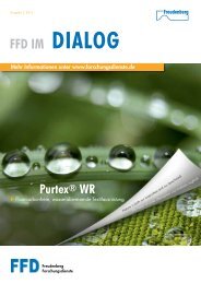
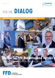
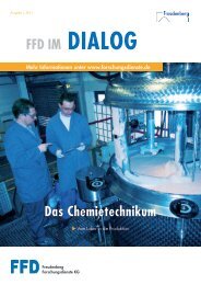
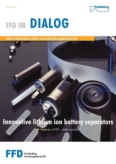
Issue 2_2012<br />
<strong>FFD</strong> <strong>IM</strong><br />
DIALOG<br />
More information under www.forschungsdienste.info<br />
Innovative lithium ion battery separators<br />
<strong>Freudenberg</strong><br />
<strong>Forschungsdienste</strong> <strong>KG</strong><br />
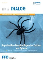
u Batteries at <strong>FFD</strong> – under scrutiny
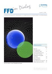
Table of contents<br />
2 Table of contents<br />
1. Editorial P. 3<br />
2. Innovative lithium ion battery separators P. 4<br />
3. RFID P. 9<br />
4. RSSR tribometer P. 14<br />
5. News from the Senior Scientists P. 17<br />
6. Seminars P. 20<br />
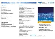
CT cut-away view of a winding cell (recorded at <strong>FFD</strong> Microscopy)
Editorial<br />
Dear Business Partners,<br />
To the great surprise of its competitors, BMW succeeded in driving<br />
home a victory already in the second race after joining in the German<br />
Touring Car Championship again. This permits a number of conclusions<br />
as regards the success factors in this fiercely contested race:<br />
To enter a new field of work, it is imperative to have a high level<br />
of knowledge and quality for known components.<br />
In the face of changed underlying conditions, it is decisive to<br />
adjust to them as quickly as possible.<br />
Innovative approaches, possibly merely innovative details, are<br />
instrumental in gaining a leading edge over competitors.<br />
Thanks to a capable, experienced and committed team, a product<br />
can rapidly become a success – whether in the preparatory<br />
phase, in the pits or in the race for victory.<br />
Some of these factors are repeatedly encountered at <strong>Freudenberg</strong>.<br />
For <strong>FFD</strong>, we will be presenting a number of examples in this issue<br />
of “<strong>FFD</strong> Dialogue”.<br />
The process of generating and saving energy will be one of the<br />
continuing challenges of the future. With its newly developed battery<br />
components, <strong>Freudenberg</strong> can play a very important role on<br />
the market (page 4). The use of what is, to all intents and purposes,<br />
known technology in other applications helps to save both<br />
costs and development time. <strong>FFD</strong> has applied RFID technology to<br />
safe work on rotating machinery (page 9). A high-speed method<br />
for selecting suitable materials and mating materials enables the<br />
developer to achieve products with a high level of operational stability<br />
within a relatively short time (page 14). Our committed team<br />
of experienced experts (page 17) and well trained organisers,<br />
engineers and scientists (page 20) ensures long-term success.<br />
I trust that you will find reading this issue both exciting and stimulating.<br />
Yours sincerely,<br />
Dr. Gerd Eßwein<br />
Editorial<br />
3
Batteries at <strong>FFD</strong> – under scrutiny<br />
InnOvAtIve LIthIuM IOn<br />
bAttery sepArAtOrs<br />
4<br />
Innovative lithium ion battery separators<br />
Introduction<br />
Battery separators are porous surface-type components which<br />
prevent electrical contact between the positive and negative elec-<br />
trodes of a battery cell yet, at the same time permit an unobstructed<br />
transport of ions between the electrodes. Ideally, separators are<br />
not involved in electrochemical reactions inside a battery, although<br />
they influence battery properties such as energy density, power<br />
density, lifetime and operational reliability to a very considerable<br />
extent. In the case of lithium ion batteries for classic applications<br />
in the 4C market (computers, cameras, cellular phones, cordless<br />
tools), separators are primarily microporous polyolefin-based<br />
(PP and / or PE) membranes. The ten largest lithium ion battery<br />
manufacturers alone need more than 450 million m 2 of separators<br />
per year (2011), with growth rates of more than 10%. The<br />
advantages of microporous membranes are their thickness (25 µm<br />
or less) and their small pore sizes (< 1 µm). The disadvantages of<br />
these membranes are their low melting point (approx. 120°C for<br />
PE and 160°C for PP), their high shrinkage rate and, in particular,<br />
their low puncture resistance with regard to electrode particles, for<br />
example. In 2011, on behalf of the French Ministry of the Environment,<br />
the French institute INERIS established that conductive particles<br />
which force their way through a separator have been one of
the main causes for internal short-circuits of lithium ion batteries.<br />
This has resulted in very cost-intensive recall campaigns by battery<br />
manufacturers. Since conventional polyolefin-based separators<br />
have the weaknesses described above, <strong>FFD</strong>, in cooperation with<br />
<strong>Freudenberg</strong> Vliesstoffe <strong>KG</strong>, has since 2007 been developing separators,<br />
particularly for large-volume lithium ion batteries. Due to<br />
their high energy content, these impose totally new requirements<br />
on the safety of batteries and thus also of separators.<br />
<strong>Freudenberg</strong>’s technology<br />
With <strong>Freudenberg</strong>’s approach (see Figure 1), an ultra-thin<br />
temperature-stable PET wet nonwoven is coated with anorganic<br />
particles and an organic bonding agent. The anorganic particles<br />
ensure excellent temperature stability and the organic bonding<br />
agents create a level of flexibility which, despite the anorganic<br />
particles, does not make the materials brittle but highly flexible.<br />
Figure 1: <strong>Co</strong>ating of a nonwoven<br />
Due to temperature stability, the separators developed by <strong>Freudenberg</strong><br />
feature a very low shrinkage rate. Figure 2 depicts a comparison<br />
between a <strong>Freudenberg</strong> separator and commercial PO membranes<br />
after a storage period of one hour at 160°C. What can be<br />
clearly seen is the shrinkage rate of the wet membrane (1, PE) and<br />
the unidirectionally stretched dry membranes (2, PP and 3, PE / PP<br />
multilayer). In both cases, the stress levels of the membranes which<br />
are frozen at room temperature are increasingly released, resulting in<br />
shrinkage and thus in a high safety risk. In contrast to conventional PO<br />
separators, <strong>Freudenberg</strong>’s products do not show any detectable shrinkage,<br />
a fact which predestines them for safety-related applications.<br />
Figure 2: <strong>Co</strong>mparison of the shrinkage rates of different lithium ion separators<br />
puncture resistance of separators – resistance desired<br />
In order to be able to determine and assess the relevant safety<br />
properties of separators, the Physical Testing Department has, over<br />
the last few years, developed and improved a series of specific test<br />
methods, including the mixed penetration test (see Figure 3), with<br />
which the puncture resistance of a separator can be determined.<br />
Innovative lithium ion battery separators<br />
5
Figure 3: Mixed penetration test<br />
Innovative lithium ion battery separators<br />
6 Innovative lithium ion battery separators<br />
In this test, the separator is located<br />
between the anode and<br />
the cathode in order to better<br />
simulate the set-up of a battery.<br />
A voltage is applied at the electrodes<br />
and then a mandrel with a<br />
semi-spherical tip is used to exert<br />
pressure on the battery component<br />
with force being continuously<br />
increased until a short-circuit<br />
results, the separator is thus damaged<br />
and the anode and the<br />
cathode come into direct contact<br />
with each other. The relevant<br />
force is measured at which the electrical resistance very suddenly<br />
falls from “infinite” to less than 100 kΩ. Figure 4 shows the results<br />
of the mixed penetration test as an example using two <strong>Freudenberg</strong><br />
samples (FV-1 and FV-2) and two conventional commercially<br />
available PO separators.<br />
Cyclical lifetime – batteries under scrutiny<br />
For purposes of everyday suitability, lithium ion batteries need not<br />
only the above-referenced safety-related properties but also a long<br />
Figure 4: <strong>Co</strong>mparison of the puncture resistance of different separators
cyclical lifetime and a high current-carrying capacity. The Applied<br />
Physics Department has developed test methods for investigating<br />
the cyclical lifetime and the current-carrying capacity and provides<br />
the necessary measuring systems. For this purpose, <strong>FFD</strong> has<br />
a multi-channel battery test system which enables the characterisation<br />
of separators in battery cells of different designs and sizes.<br />
Due to programmable application software for automated test<br />
procedures and data evaluation, measurements can be efficiently<br />
performed at the battery test bay. In addition to the standardised<br />
test processes from the available test catalogue, customer-specific<br />
test requirements, e.g. battery tests in climatic chambers, are also<br />
taken into consideration.<br />
A large number of factors determine whether the nominal cyclical<br />
lifetime is reached. The temperature and discharge current (also<br />
referred to as “C rate”) apply as the most important contributory<br />
parameters. The C rate specifies the electrical load relative to nominal<br />
capacitance. At a C rate of 0.5, a rechargeable battery with<br />
a nominal capacitance of 2000 mAh is discharged at a current of<br />
1000 mA. Under ideal conditions (temperature of 20°C, current<br />
of 1C nominal ), commercially available series cells should have at<br />
least 75% of their initial capacitance after more than 500 complete<br />
charging / discharging cycles. Figure 5 shows the cyclical<br />
lifetime of type 18650 winding cells with <strong>Freudenberg</strong> separators.<br />
Figure 5: Determination of cyclical lifetime<br />
To ensure effective usage of the overall capacitance of a rechargeable<br />
battery, battery manufacturers recommend a defined<br />
electrical load at approx. one fifth of the nominal current, i.e. at<br />
approx. 0.2 C. When increasing the current load to many times the<br />
nominal capacitance, the actually usable capacitance decreases<br />
significantly, this being due to the load-dependent increase in<br />
internal battery resistance. Due to its material properties and<br />
coating topology, the separator in use makes a by no means<br />
negligible contribution to a cell’s internal resistance.<br />
Figure 6 shows the load-dependent capacitance of lithium ion<br />
batteries with identical electrodes but different separators which<br />
means that differences in capacitance are attributable to the se-<br />
Innovative lithium ion battery separators<br />
7
Figure 6: <strong>Co</strong>mparison of discharge rate-dependent capacitance of different<br />
lithium ion batteries<br />
Innovative lithium ion battery separators<br />
8<br />
Innovative lithium ion battery separators<br />
parator. The influence of the separator<br />
on capacitance is easily<br />
discernible, with FV2A being the<br />
first developed separator and<br />
FV2B, FV2B2 and FV1C the separators<br />
which have been optimised<br />
in terms of internal resistance.<br />
<strong>Co</strong>mparison of the capacitances<br />
shows that, due to a continuous<br />
improvement in coating recipes<br />
for separators, the actually usable<br />
battery capacitance has<br />
been increased.<br />
<strong>Co</strong>nclusion<br />
It has been shown that innovative lithium ion battery separators<br />
have been developed featuring not only good electrochemical behaviour<br />
but also, in particular, considerably improved safety properties<br />
which distinguish them from conventional PO separators.<br />
In addition to their very low shrinkage rate, these separators have<br />
a very high puncture resistance which particularly recommends<br />
them for large-surface, safety-related lithium ion cells in both<br />
stationary and mobile applications. Alongside separator development,<br />
over the last few years an almost complete test catalogue<br />
for the characterisation of separators and lithium ion batteries<br />
has been put together at <strong>FFD</strong>. In 2011, the market for lithium ion<br />
separators was more than 450 million m 2 with a continued high<br />
growth rate in which <strong>Freudenberg</strong> wishes to participate.<br />
your contacts:<br />
Marina Senina<br />
Physical Testing<br />
Tel.: +49 (0)6201 - 80 38 27<br />
Fax: +49 (0)6201 - 80 38 27<br />
marina.senina@<br />
freudenberg.de<br />
Süleyman Altuncu<br />
Tel.: +49 (0)6201 - 80 49 55<br />
Fax: +49 (0)6201 - 80 30 63<br />
sueleyman.altuncu@<br />
freudenberg.de<br />
Dr. Michael Roth<br />
Tel.: +49 (0)6201 - 80 52 60<br />
Fax: +49 (0)6201 - 80 52 60<br />
michael.rath@freudenberg.de
As non-contact machine guards<br />
rFID<br />
Introduction:<br />
In many processes, it is still imperative to move items to be processed<br />
to the processing point by hand. Classic examples to this<br />
effect may be found in mechanical workshops. Circular and band<br />
saws, chamfering benches and sheet-metal bending machines<br />
may be primarily referred to as examples. However, in typical processes<br />
at <strong>Freudenberg</strong>, such as the mixing and rolling of rubber<br />
compounds or foularding, manual handling is required in some<br />
cases. In all these specified processes, staff are inevitably exposed<br />
to a potential hazard.<br />
As conventional protection of staff in danger zones, three possibilities<br />
are available, although they are subject to restrictions:<br />
Permanent separating machine guards. In this case, production<br />
items cannot be moved to the processing point by hand.<br />
Movable separating machine guards. If a guard door is used,<br />
the machine is emergency-stopped. Movable machine guards<br />
with an approach function generally have recesses through<br />
which the production item can pass. If the guard is moved by<br />
part of the operator’s body, an emergency stop is triggered. The<br />
disadvantage is that, for many production items, the recess has<br />
RFID<br />
9
RFID<br />
10 RFID<br />
to be so large that the operator’s arm, for example, can also<br />
access the danger zone or the recess has to be dimensioned<br />
sufficiently small so that an emergency stop is triggered by a<br />
production item when passed through.<br />
Non-contact machine guards. Such available guards, such as<br />
light curtains, cannot distinguish between a production item and<br />
part of an operator’s body.<br />
For some applications, RFID (radio-frequency identification) technology<br />
is suitable for the installation of a machine guard. RFID<br />
uses electromagnetic waves for identification purposes.<br />
This technology is actually familiar to everyone as it is used in antitheft<br />
tagging systems in department stores. Articles of clothing are<br />
often fitted with a transponder (or radio tag). Devices which create<br />
an electrical field are positioned at the entrances to department<br />
stores. The transponder detects the electrical field on approaching<br />
it and sends a signal to an evaluation unit which generates an<br />
acoustic signal prompting the customer with an unpaid-for item to<br />
think twice before leaving the premises and to pay for the article<br />
in question.<br />
This principle can also be used on a machine guard.<br />
Function and elements of an rFID machine guard<br />
For the reasons outlined above, <strong>FFD</strong> decided in 2010 to introduce<br />
a RFID machine guard on a laboratory roller mill. This system comprises<br />
a limited number of components. The antenna is the core<br />
element of the system. It generates the electrical field (protective<br />
field) and consists of an extended conductor through which a current<br />
flows. Using a low-frequency AC current (9 kHz), a cylindrical<br />
magnetic field is generated which has a very high level of penetration<br />
through almost all materials. The antenna is positioned in<br />
parallel to the roller clearance above the rollers.<br />
To protect the operator’s hands, two transponders have to be worn<br />
on his or her wrists. Each transponder detects the field and sends<br />
a signal to the evaluation unit. In the X, Y and Z directions, the<br />
transponders are fitted with a coil which means that it is irrelevant<br />
how a transponder enters the field.
In our case, active transponders are used which draw the energy<br />
needed for signal transmission from a battery.<br />
The evaluation unit receives the signals sent by the transponders<br />
and the self-test module. These signals are redundantly processed<br />
by the control unit. The evaluation unit supplies the signal for triggering<br />
an emergency stop to the machine’s control unit.<br />
These imperative functional units are supplemented by different<br />
additional devices which are to ensure that functionality is permanently<br />
monitored. For visual display of the protective field boundary,<br />
a linear laser is used to project a mark on the roller. Since it is<br />
absolutely necessary for the machine guard to continuously check<br />
whether the protective field is available, a self-test module is used.<br />
This module is positioned in the protective field which it monitors.<br />
As soon as the protective field is no longer available, the self-test<br />
module sends a signal to the evaluation unit and the machine is<br />
emergency-stopped. This could, for example, be the case due to a<br />
broken cable or a power failure.<br />
To ensure that the transponders are applied, they have to be<br />
logged on at a log-on unit. It is only then that the system can be<br />
started. Successful log-on provides the operator with the information<br />
that the battery still has a lifetime of at least eight hours. In the<br />
case of our roller mill, log-on has to be repeated after a pre-set<br />
time in order to ensure that rolling is continuously monitored by a<br />
member of staff. The roller mill is then emergency-stopped upon<br />
expiry of this time.<br />
The objective was to achieve a finalised safety concept with a very<br />
high level of protection in the system. For this reason, traditional<br />
machine guards were also kept. <strong>FFD</strong>’s roller mill continues to be<br />
equipped with emergency stop pushbuttons, toggle triggers and<br />
a cut-off rocker. The rocker as a machine guard with an approach<br />
function has, however, been modified so that the roll of uncured<br />
rubber can be rolled and turned out and the additives dosed in<br />
an ergonomically favourable manner, providing optimum process<br />
possibilities.<br />
rFID workshop<br />
<strong>FFD</strong> invited colleagues interested in this subject to participate in<br />
the RFID workshop<br />
to present the mode of operation of an RFID machine guard<br />
to discuss the possibilities and limits of application<br />
to develop suitable decision-making aids for usage<br />
and thus to define underlying conditions for usage at <strong>Freudenberg</strong><br />
At this workshop, RFID technology was presented by the manufacturer.<br />
During the talk given, if became clear that a wide range of<br />
different possible applications are conceivable.<br />
RFID 11
RFID<br />
12 RFID<br />
The theory block was rounded off by a close look at the laboratory<br />
roller mill in <strong>FFD</strong>’s Elastomers Pilot Plant . All participants had the<br />
possibility of seeing for themselves the different functional elements.<br />
They found it particularly interesting to talk with colleagues on site<br />
who already work with the RFID machine guard. It was in this connection<br />
that a specially positive aspect became clear. Although the<br />
machine guard is not mandatory since the transponders have to<br />
be worn by staff, a high level of motivation to do so is apparent<br />
since the RFID machine guard permits considerably more ergonomic<br />
work than was previously the case. The roll of uncured rubber is<br />
now rolled in an ergonomically more favourable working position<br />
and, in order to be turned out into the clearance between the rollers,<br />
it need not be lifted over a separating machine guard.<br />
Finally, there was an intensive discussion about which technical<br />
and organisational basic conditions have to exist for suitable<br />
usage of this technology.<br />
basic conditions for application of rFID technology as machine guards<br />
The relevant workplaces have to be continuously manned by a<br />
limited number of staff. Machinery which is used by many<br />
persons for brief activities is not suitable. For example, it is not<br />
very likely that staff who use a band saw in a workshop for short<br />
periods only always think of wearing the transponders.<br />
Only machinery should be considered on which process items<br />
are currently moved to the processing point by hand. Machinery<br />
on which a fixed or movably separating or non-contact machine<br />
guard is suitable without restricting the process possibilities is<br />
unsuitable for the use of RFID. Such examples include injection<br />
moulding machines and presses.<br />
The technology must be “just right”. For example, the switching<br />
times and the braking distances of the machine have to be<br />
designed in such a way as to permit safe braking before the<br />
hazard point can be reached.
examples of suitable machinery<br />
Old machinery, e.g. old roller mills which have not yet been<br />
fitted with machine guards or which are only protected by a<br />
Bowden cable emergency stop above the clearance between<br />
the rollers<br />
Bale openers, waste presses<br />
basic conditions for organisation<br />
Hazard evaluation with an analysis of the residual hazards<br />
Limitation of the number of staff to a minimum<br />
Operating instructions and briefing<br />
Regular adjusted checking of the emergency stop function<br />
<strong>Co</strong>nclusion<br />
<strong>FFD</strong>’s experience shows that, under certain defined conditions and<br />
constraints, an RFID machine guard can make a very positive contribution<br />
to machine safety. A key factor is the readiness of staff<br />
to move over from a “visible” separating machine guard to an<br />
“invisible” one. Active staff involvement from the very beginning is<br />
a basic condition for the usage of such systems.<br />
your contact:<br />
Ulrich Freund<br />
Tel.: +49 (0)6201 - 80 42 74<br />
Fax: +49 (0)6201 - 80 30 63<br />
ulrich.freund@<br />
freudenberg.de<br />
RFID 13
Establishment of a test method…<br />
rssr trIbOMeter<br />
14 RSSR Tribometer<br />
… required for rapid assessment of elastomer / lubricant combinations<br />
Introduction<br />
For the design of dynamic seals with radial shaft sealing rings<br />
(RSSR), not only a large number of other influencing factors but<br />
also the selection of suitable elastomer / oil combinations plays<br />
a decisive role. At present, no standardised test method exists for<br />
the purpose of recording the wear and friction of simple material<br />
samples, taking into consideration operating conditions such as<br />
sealing geometry, contact force, circumferential speed and temperature.<br />
For investigations of elastomer / oil combinations on radial<br />
shaft sealing rings, it is, due to different shrinkage behaviour,<br />
frequently imperative to produce a separate sample tool for each<br />
elastomer compound.<br />
In order to exclude material combinations which are unsuitable at<br />
an early stage, the RSSR tribometer was developed and tested as<br />
a dynamic test method within the context of project 664 of DGMK<br />
(German Society for Petroleum and <strong>Co</strong>al Science and Technology),<br />
enabling a preselection of suitable materials on the basis of<br />
easy-to-manufacture elastomer samples. In order to establish this
test method as a standard, we are currently searching for partners<br />
who are interested in jointly implementing such a solution.<br />
Design and mode of operation<br />
The basic design of the RSSR<br />
tribometer is depicted in Figure<br />
1. A circular ring-shaped ela-<br />
stomer test specimen is pressed,<br />
at a defined force, against a<br />
truncated-cone shaft test specimen.<br />
The contact area between<br />
both test specimens represents<br />
the contact between the radial<br />
shaft sealing ring and the shaft<br />
itself.<br />
The shaft test specimen is dri-<br />
Figure 1: Mode of operation of the RSSR tribometer<br />
ven via a shaft and the moment<br />
transferred to the elastomer test<br />
specimen is recorded. The contact area is located in a container<br />
filled with the test oil. The area below the elastomer test specimen<br />
can be filled with air.<br />
In addition to selecting the<br />
materials for the elastomer test<br />
specimen, shaft test specimen<br />
and test oil, the parameters oil<br />
sump temperature, circumferential<br />
speed and contact force<br />
can be set. Figure 2 shows the<br />
course of the friction moment<br />
for different test oils when<br />
using a test specimen made<br />
of nitril butadiene rubber during<br />
the 20-day standard test<br />
Figure 2: Tests with RSSR and RSSR tribometer<br />
procedure. Furthermore, the<br />
influence of the three cycles<br />
(see Figure 2) in which the circumferential speed is varied can be<br />
clearly seen.<br />
results from investigations on radial shaft sealing rings and<br />
rssr tribometer in comparison<br />
The basic suitability of the RSSR tribometer is examined by investigations<br />
of a sample elastomer / oil combination of a nitril butadiene<br />
rubber with a conventional mineral oil, and the results of the<br />
RSSR tribometer are compared with those of radial shaft sealing<br />
rings of the same material. Figure 3 shows the influence of the parameters<br />
oil sump temperature and circumferential speed at the sti-<br />
RSSR Tribometer 15
Figure 3: Test procedure: a NBR with five oils in comparison<br />
RSSR Tribometer<br />
Figure 4: <strong>Co</strong>mparison of wear sustained by the RSSR and the RSSR tribometer<br />
16 RSSR Tribometer<br />
realisation<br />
pulated linear load. In the case<br />
of the RSSR tribometer and the<br />
radial shaft sealing ring, the<br />
influence on wear (see Figure<br />
4) is comparable. Due to the<br />
radial force which, during the<br />
test, decreases in the case of<br />
the radial shaft sealing ring as<br />
a result of the change in temperature<br />
and wear, the RSSR<br />
tribometer, however, causes<br />
wear to increase at about<br />
twice the rate.<br />
The investigations show that<br />
testing with the RSSR tribometer<br />
is highly suitable for the<br />
purpose of comparing material<br />
combinations. Further standardisation<br />
of the test method is<br />
currently the subject of DGMK<br />
project 738.<br />
Investigations performed so far are taking place at ten prototype test<br />
bays of TUHH. Partners from the DGMK project have approached<br />
us in order to assume responsibility for the construction, sales and<br />
servicing of such dual test bays.<br />
At present, on the basis of these prototypes, marketable test bays<br />
are being realised in the form of dual test bays. In order to esta-<br />
blish the new method on as broad a basis as possible, we are currently<br />
searching for further partners and potential customers who<br />
wish to use such a method within the context of development and<br />
selection of elastomer seals and / or lubricants and participate in<br />
the realisation of test bays or who are interested in acquiring RSSR<br />
tribometer test bays.<br />
your contacts:<br />
Dr. Stefan Sindlinger<br />
Tel.: +49 (0)6201 - 80 36 90<br />
Fax: +49 (0)6201 - 80 36 90<br />
stefan.sindlinger@<br />
freudenberg.de<br />
Dr. Ravindrakumar Bactavatchalou<br />
Tel.: +49 (0)6201 - 80 24 36<br />
Fax: +49 (0)6201 - 88 51 91<br />
ravindrakumar.bactavatchalou@<br />
freudenberg.de
News from the Senior Scientists<br />
Figure 1: Input of the major stretches in the “invariant” app<br />
Mobile engineering by “app” no longer a dream of the future<br />
… was the headline in the newspaper published by the Association<br />
of German Engineers “VDI-Nachrichten” in April 2011 and<br />
was repeated in a similar form in April 2012. <strong>FFD</strong>, too, is facing<br />
up to this challenge and is currently investigating possibilities of<br />
providing appropriate services for mobile technical applications.<br />
Within this context, Dr. Baaser has, together with two students<br />
from Bingen University of Applied Sciences, developed an app<br />
which maps his basic investigations for representing possible deformation<br />
modes of elastomers onto the plane of invariants.<br />
Figure 2: Graphic output of deformation on the plane of invariants I 1 -I 2<br />
The classic material models for<br />
elastomers are based on the<br />
deformation invariants; exten-<br />
sions of these models are at least<br />
based on these classic descriptions.<br />
This raises the question,<br />
also in discussions with customers,<br />
regarding a suitable visualisation<br />
of current deformations<br />
in rubber components. As early<br />
as in the mid-20th century, Prof.<br />
L.R.G. Treloar was concerned<br />
with this task and, to this effect,<br />
suggested the representation<br />
of all possible deformations of<br />
rubber materials on the plane<br />
of invariants. Thus, it is very<br />
impressively possible to classify<br />
all deformations between the<br />
uni-axial and bi-axial prototype<br />
modes.<br />
The assessment of these modes<br />
is a crucial aspect of [1] and<br />
[2] and aims later at lifetime<br />
estimation for elastomers. The<br />
Adjunct professor Dr.-Ing. habil.<br />
herbert baaser<br />
Senior Engineer for Physical<br />
Material Properties and Life<br />
Cycle<br />
Tel.: +49 (0)6201 - 80 68 82<br />
Fax: +49 (0)6201 - 88 30 84<br />
News from the Senior Scientists 17
Figure 3: LEVITEX crankshaft seal, 1999 –<br />
2003<br />
News from the Senior Scientists<br />
18 News from the Senior Scientists<br />
user interface of this app currently comprises two screens<br />
on a mobile device with Android or the Apple operating<br />
system. The first page (see Figure 1) is primarily for the<br />
purpose of entering two stretches of the material. This deformation<br />
is then visualised in the graphic output of the<br />
second page (Figure 2) on the plane of invariants for incompressible<br />
materials.<br />
If you have any suggestions or other ideas on this complex<br />
subject, please contact Dr. Baaser who would be delighted<br />
to provide you with this application as a “tool” and for<br />
demonstration purposes.<br />
<strong>FFD</strong>’s CAe supports LevIteX developments for Fst-Ape and burgmann-<br />
Automotive<br />
An idea and development of Burgmann Automotive<br />
for gas-lubricated crankshaft seals, now ten<br />
years old, have been picked up at FST again.<br />
This sealing concept is currently being refined at<br />
FST under the aspect of CO2 savings within the<br />
context of the LESS (Low Emissions Sealing Solution)<br />
package. A new approach in which an elastomer<br />
spring is to be used in combination with<br />
megaseries-suitable face geometries is shown<br />
as a cross-section in Figure 4. It is thus possible<br />
to reduce manufacturing costs to such an extent<br />
that cost-effective usage is directly worthwhile. In<br />
addition, benefits result due to the elastomer<br />
spring since the friction-prone ancillary seal , as<br />
used in conventional crankshaft seals, is no longer<br />
needed. The first few studies on this concept<br />
have evolved with Burgmann’s calculation program<br />
for crankshaft seals in cooperation with<br />
Dr. Klaus Lang of Burgmann (Wolfratshausen).<br />
Figure 4: Design and refinement of Burgmann’s LEVITEX<br />
The first design of the elastomer spring was re-<br />
seal<br />
alised using <strong>FFD</strong>’s WebFEM program. For complete<br />
optimisation of the functionality and harmonisation of the<br />
components, Burgmann’s calculation program is now being linked<br />
to Dr. Baaser’s developments. This enables a computer-aided structural<br />
optimisation of the overall concept. At this point, there is also
Figure 5: Axi-symmetrical FE model of an elastomer spring<br />
Figure 6: Axial stress in the cross-section of the elastomer spring<br />
close cooperation with Frank<br />
Schönberg who analyses such<br />
optimisation procedures within<br />
the context of robust design in<br />
cooperation between FST, <strong>FFD</strong>’s<br />
CAE and the University of Technology,<br />
Darmstadt.<br />
For structural optimisation of the<br />
elastomer spring, in this project,<br />
a special element formulation<br />
including material behaviour for<br />
elastomers has been implement-<br />
ed on the basis of a separate<br />
FEM program system DAEdalon<br />
which is freely available on the<br />
internet as open-source software<br />
under www.DAEdalon.org. The<br />
possibilities offered by such a<br />
software package have already<br />
been presented in a book (Figure<br />
7) authored by Dr. Baaser and<br />
have now been used for a development<br />
at FST for the first time.<br />
Figure 5 shows the axi-symmetrical<br />
model of the crankshaft seal’s<br />
elastomer spring; a calculation<br />
result obtained in the course of<br />
structural optimisation is specified<br />
in Figure 6. The resulting axial<br />
stress (in N/m²= Pa) is shown.<br />
(1) Baaser, H.: FEM-Simulation von Elastomerbauteilen. ATZ – Automobiltechnische<br />
Zeitschrift, April 5, 2010<br />
(2) Baaser, H., Schobel, A., Michaeli, M., Masberg, U.: Vergleich von äquibiaxia-<br />
len Prüfständen zur Kalibrierung von Werkstoffmodellen, Kautschuk Gummi Kunststoffe,<br />
May 2011<br />
(3) Baaser, H.: Development and Application of the Finite Element Method based<br />
on MatLab, Springer, 2010<br />
<strong>Co</strong>ntact:<br />
Adjunct Professor Dr.-Ing. habil. Herbert Baaser<br />
Senior Engineer for Physical Material Properties and Life Cycle<br />
Tel.: +49 (0)6201 - 80 68 82<br />
Fax: +49 (0)6201 - 88 30 84<br />
herbert.baaser@freudenberg.de<br />
Figure 7: Book on DAEdalon<br />
News from the Senior Scientists 19
to register, please contact:<br />
Ms. Ulrike Kast<br />
Tel.: +49 (0)6201 - 80 48 80<br />
Fax: +49 (0)6201 - 88 30 63<br />
ulrike.kast@freudenberg.de<br />
Seminars at <strong>Freudenberg</strong> <strong>Forschungsdienste</strong> <strong>KG</strong><br />
Location: <strong>FFD</strong>,<br />
Höhnerweg 2–4,<br />
69465 Weinheim<br />
Fee: EUR 1,350<br />
plus VAT<br />
Date: 07. - 08.11.2012<br />
Location: <strong>FFD</strong>,<br />
Höhnerweg 2–4,<br />
69465 Weinheim<br />
Fee: EUR 1,050<br />
plus VAT<br />
Date: 20. - 21.11. 2012<br />
20 Seminars<br />
r&D Funding by the German state –<br />
non-repayable Grants for your <strong>Co</strong>mpany<br />
Target group: This seminar is aimed at all project managers who<br />
wish to submit a funding application or who have already applied<br />
for/been granted funding for their R&D project. This is of relevance<br />
to anyone wishing to round off their knowledge about ruleconformant<br />
processes and requiring decision-making assistance.<br />
<strong>Co</strong>ntents: The participants find out how their company can profit<br />
from state R&D funding. Knowledge about formal processes from<br />
the preparation of an outline through to project close-out including<br />
price checking is provided. Important elements of the prescribed<br />
cooperation agreement, e.g. know-how protection, are presented.<br />
The experienced speakers provide tips from everyday administration<br />
practice in which they have successfully implemented numerous<br />
R&D funding projects.<br />
seminar on Failure Analysis in plastic <strong>Co</strong>mponents<br />
Seminar management: Siljana Lietz, <strong>FFD</strong> / Dr.-Ing. habil. Sonja Pongratz, VW<br />
This seminar is aimed at engineers and technicians who wish to<br />
gain a thorough understanding of failure mechanisms in plastic<br />
components and become familiar with methods of systematic causal<br />
analysis. At this seminar, possible causes of failure in moulded<br />
parts and the methods of investigation used in failure analysis will<br />
be presented. The systematic processing of instances of failure will<br />
be demonstrated using a guideline.<br />
seminar on rubber / Metal bonding<br />
Seminar management: Dr. Michael Ballhorn<br />
This seminar is aimed at engineers, chemists, technicians and machine<br />
operators involved in the area of rubber / metal bonding.<br />
<strong>Co</strong>ntents: rubber: classes, processing and bonding capacity; metal:<br />
cleaning, pretreatment (mechanical, chemical, phosphating),<br />
wetting; bonding agents: composition and effects, application,<br />
adhesion mechanisms, rubber and surface analytics, approaches<br />
and remedial measures in cases of failure, practical demonstrations<br />
and exercises.<br />
to register, please contact:<br />
Ms. Sonja Heinzelbecker, tel. +49 (0)6201 - 80 55 63,<br />
fax +49 (0)6201 - 88 55 63, sonja.heinzelbecker@freudenberg.de<br />
Location: <strong>Freudenberg</strong>,<br />
Building 23,<br />
Höhnerweg 2-4<br />
69469 Weinheim,<br />
Fee: EUR 500 plus<br />
VAT for<br />
<strong>Freudenberg</strong> staff,<br />
EUR 750 plus<br />
VAT for<br />
external participants<br />
Date: 15.11.2012,<br />
8.45 a.m. - 5 p.m.
Location: FST Academy<br />
Building 75<br />
Fee: Euro 690 plus VAT<br />
Date: 09./10.10.2012<br />
Location: FST Academy<br />
Building 75<br />
Fee: Euro 690 plus VAT<br />
Date: 23./24.10.2012<br />
Location: FST Academy<br />
Building 75<br />
Fee: Euro 690 plus VAT<br />
Date: 20./21.11.2012<br />
Location: FST Academy<br />
Building 75<br />
Fee: Euro 690 plus VAT<br />
Date: 11./12.12.2012<br />
Location: <strong>FFD</strong> Building 32<br />
Fee: Euro 690 plus VAT<br />
Date: 18./19.12.2012<br />
Location: <strong>FFD</strong> Building 32<br />
Fee: Euro 690 plus VAT<br />
Date: 06./07.11.2012<br />
seminar series “elastomers processing at <strong>Freudenberg</strong>“<br />
Seminar management: Dr.-Ing. Andreas Kammann<br />
The seminars are aimed principally at participants with a technical<br />
or scientific background and are especially suitable for those<br />
employees new to the company in the areas of production, development<br />
and marketing, etc. The aim of the seminars is to enable<br />
them to familiarise themselves quickly and in a targeted way with<br />
what for most is an unknown field.<br />
Module 1: Materials 1<br />
Principles of polymer chemistry; what is “rubber”? deterioration<br />
protection and fillers; plasticisers and auxiliary products; general-<br />
purpose rubber; high-performance rubbers and specialities; technical<br />
thermoplastics as metal substitutes; thermoplastic elastomers (TPE).<br />
In cooperation with the FDS Academy<br />
Module 2: Materials 2<br />
Dynamic-mechanical behaviour of polymers; bonding of rubber;<br />
practical; surface modification and tribology; liquid silicone rubber;<br />
REACH; threats and opportunities of nanotechnology; formula<br />
optimisation; technical thermoplastics as metal substitute; polyurethanes.<br />
In cooperation with the FDS Academy<br />
Module 3: processes 1<br />
Technology of mixing; visit to the rubber mixing facility, mixing<br />
process in internal mixers, alternative mixing processes; development<br />
of the mixing process; principles of vulcanisation; vulcanisation<br />
process; special processes; TPE fabrication; moulding preparation;<br />
process data processing.<br />
In cooperation with the FDS Academy<br />
Module 4: processes 2<br />
Processing following the internal mixer; scale-up; influence of the<br />
mixing process on constituent characteristics; approaches to mix-<br />
ing process optimisation; manufacture of natural rubber flooring;<br />
process optimisation in elastomers processing; finishing of mould-<br />
ed rubber parts; thorough examination of processing processes;<br />
rapid prototyping.<br />
In cooperation with the FDS Academy<br />
Module 5: products<br />
In this seminar, the developers of various product areas deal with<br />
the basic physical properties of their product groups. The participants<br />
are given a broad outline of the entire range of products<br />
of <strong>Freudenberg</strong> Seals and Vibration <strong>Co</strong>ntrol Technology and of<br />
Vibracoustic.<br />
Module 6: Mould technology and Mould Cleaning<br />
Mould steel, cold runner technology, mould coatings, physicaltechnical<br />
principles of mould cleaning, microblasting, cleaning<br />
with dry ice (including practical demonstration), laser cleaning<br />
(including practical demonstration), ultrasonic cleaning, separa-<br />
Seminars<br />
21
Location: <strong>FFD</strong> Building 32<br />
Fee: Euro 690 plus VAT<br />
Date: 16./17.10.2012<br />
Location: <strong>FFD</strong> Building 32<br />
Fee: Euro 450 plus VAT<br />
Date: 19.10.2012<br />
Location: <strong>FFD</strong> Building 32<br />
Fee: Euro 950 plus VAT<br />
Date: 22./23.01.2013<br />
Location: <strong>FFD</strong> Building 32<br />
Fee: Euro 950 plus VAT<br />
Date: 06./07.12.2012<br />
Location: <strong>FFD</strong> Building 32<br />
Fee: Euro 450 plus VAT<br />
Date: 16.11.2012<br />
22 Seminars<br />
ting agents for elastomers processing, fundamentals of mould technology,<br />
rapid tooling, design of injection molds, laser structuring.<br />
Module 7: test Methods and Analytics<br />
Static test methods, dynamic test methods, lifetime prediction,<br />
consistency tests, caloric properties, optical microscopy, scanning<br />
electron microscopy, elastomer analytics, failure analysis.<br />
seminars on Other subjects<br />
Seminar management: Dr.-Ing. Andreas Kammann<br />
From Caoutchouc to rubber – a starter seminar<br />
This seminar answers a number of basic questions on elastomer<br />
chemistry: What is rubber at all and what is caoutchouc? How is<br />
caoutchouc made into rubber? Why do so many different components<br />
become part of a rubber compound? What actually happens<br />
during moulding and vulcanisation? Why are there so many<br />
different types of caoutchouc?<br />
polyurethanes – Materials and processing<br />
Basics of polymer chemistry, raw materials for polyurethanes,<br />
processing methods (casting, R<strong>IM</strong>, injection moulding, extrusion,<br />
foaming, impregnation, etc.); mechanical and chemical properties;<br />
analytical investigations.<br />
practical seminar: Installation of an Injection-Moulding Machine and<br />
troubleshooting<br />
This seminar is aimed at all machine operators who have al-<br />
ready gained initial experience in the processing of elastomers and<br />
are, in future, to work more independently due to a more in-depth<br />
understanding of the process and assume tool setter duties. <strong>Co</strong>ntent:<br />
basics of elastomer injection moulding, practical set-up of an<br />
injection-moulding machine, fault detection and remedial measures.<br />
Industrial property rights – patents, trademarks and Designs<br />
This seminar is aimed at anyone who is involved in the development<br />
and marketing of technical products (chemical engineers,<br />
chemists, engineers, technical specialists, material developers,<br />
purchasers, sales staff and commercial administrators). <strong>Co</strong>ntent:<br />
patents, utility models, trademarks, designs, protective range of a<br />
patent or design, patent strategy.<br />
Further information<br />
on our range of seminars may be found at any time under:<br />
www.forschungsdienste.info<br />
to register, please contact:<br />
Ms. Simone Horn, tel. +49 (0)6201 - 80 48 80,<br />
fax +49 (0)6201 - 88 30 63, simone.horn@freudenberg.de<br />
We reserve the right to reject requests for registration submitted by staff from<br />
the competitors of the <strong>Freudenberg</strong> Group.
Impressum<br />
<strong>Freudenberg</strong><br />
<strong>Forschungsdienste</strong> <strong>KG</strong><br />
Published by: <strong>Freudenberg</strong> <strong>Forschungsdienste</strong> <strong>KG</strong>,<br />
69465 Weinheim<br />
Germany<br />
Editor-in-Chief: Martin Gramlich<br />
Editorial Staff: Dr. Katharina Müller, Andrea Deis,<br />
Ulrike Kast, Sabrina Lemke,<br />
Dr. Christof Schmitz,<br />
Dr. Ulrike Herrlich, Dr. Franka Geiß<br />
Layout: Ehret Design, www.ehretdesign.de<br />
<strong>Freudenberg</strong> <strong>Forschungsdienste</strong> <strong>KG</strong><br />
69465 Weinheim (an der Bergstraße)<br />
Telefon +49(0)6201 80-5123<br />
E-Mail ffd@freudenberg.de<br />
www.forschungsdienste.de<br />
23