System 184 XT - Fagerberg
System 184 XT - Fagerberg
System 184 XT - Fagerberg
- No tags were found...

You also want an ePaper? Increase the reach of your titles
YUMPU automatically turns print PDFs into web optimized ePapers that Google loves.
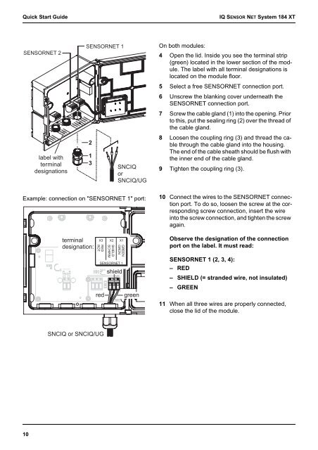
GREENGRÜNSHIELDSCHIRMREDROTQuick Start GuideIQ SENSOR NET <strong>System</strong> <strong>184</strong> <strong>XT</strong>SENSORNET 2label withterminaldesignationsSENSORNET 1213SNCIQorSNCIQ/UGOn both modules:4 Open the lid. Inside you see the terminal strip(green) located in the lower section of the module.The label with all terminal designations islocated on the module floor.5 Select a free SENSORNET connection port.6 Unscrew the blanking cover underneath theSENSORNET connection port.7 Screw the cable gland (1) into the opening. Priorto this, put the sealing ring (2) over the thread ofthe cable gland.8 Loosen the coupling ring (3) and thread the cablethrough the cable gland into the housing.The end of the cable sheath should be flush withthe inner end of the cable gland.9 Tighten the coupling ring (3).Example: connection on "SENSORNET 1" port:10 Connect the wires to the SENSORNET connectionport. To do so, loosen the screw at the correspondingscrew connection, insert the wireinto the screw connection, and tighten the screwagain.terminaldesignation:X3 X2 X1Observe the designation of the connectionport on the label. It must read:SENSORNET 1shieldred greenSENSORNET 1 (2, 3, 4):– RED– SHIELD (= stranded wire, not insulated)– GREEN11 When all three wires are properly connected,close the lid of the module.SNCIQ or SNCIQ/UG10