Road King Manual - Mesa Boogie
Road King Manual - Mesa Boogie
Road King Manual - Mesa Boogie
- No tags were found...
Create successful ePaper yourself
Turn your PDF publications into a flip-book with our unique Google optimized e-Paper software.
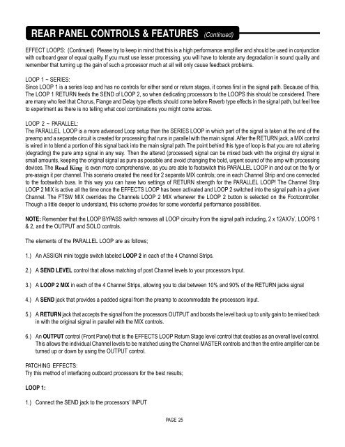
REAR PANEL CONTROLS & FEATURES (Continued)EFFECT LOOPS: (Continued) Please try to keep in mind that this is a high performance amplifier and should be used in conjunctionwith outboard gear of equal quality. If you must use lesser processing, you will have to tolerate any degradation in sound quality andremember that turning up the gain of such a processor much at all will only cause feedback problems.LOOP 1 ~ SERIES:Since LOOP 1 is a series loop and has no controls for either send or return stages, it comes first in the signal path. Because of this,The LOOP 1 RETURN feeds the SEND of LOOP 2, so when dedicating processors to the LOOPS this should be considered. Thereare many who feel that Chorus, Flange and Delay type effects should come before Reverb type effects in the signal path, but feel freeto experiment as there is no telling what cool combinations you might come across.LOOP 2 ~ PARALLEL:The PARALLEL LOOP is a more advanced Loop setup than the SERIES LOOP in which part of the signal is taken at the end of thepreamp and a separate circuit is created for processing that runs in parallel with the main signal. After the RETURN jack, a MIX controlis wired in to blend a portion of this signal back into the main signal path. The point behind this type of loop is that you are not altering(degrading) the pure amp signal in any way. Then the altered (processed) signal can be mixed back with the original dry signal insmall amounts, keeping the original signal as pure as possible and avoid changing the bold, urgent sound of the amp with processingdevices. The <strong>Road</strong> <strong>King</strong> is even more comprehensive, as you are able to footswitch this PARALLEL LOOP in and out on the fly orpre-assign it per channel. This scenario created the need for 2 separate MIX controls; one in each Channel Strip and one connectedto the footswitch buss. In this way you can have two settings of RETURN strength for the PARALLEL LOOP! The Channel StripLOOP 2 MIX is active all the time once the EFFECTS LOOP has been activated and LOOP 2 switched into the signal path in a givenChannel. The FTSW MIX overrides the Channels LOOP 2 MIX whenever the LOOP 2 button is selected on the Footcontroller.Though a little deeper to understand, this scheme provides for some wonderful performance possibilities.NOTE: Remember that the LOOP BYPASS switch removes all LOOP circuitry from the signal path including, 2 x 12AX7s’, LOOPS 1& 2, and the OUTPUT and SOLO controls.The elements of the PARALLEL LOOP are as follows;1.) An ASSIGN mini toggle switch labeled LOOP 2 in each of the 4 Channel Strips.2.) A SEND LEVEL control that allows matching of post Channel levels to your processors Input.3.) A LOOP 2 MIX in each of the 4 Channel Strips, allowing you to dial between 10% and 90% of the RETURN jacks signal4.) A SEND jack that provides a padded signal from the preamp to accommodate the processors Input.5.) A RETURN jack that accepts the signal from the processors OUTPUT and boosts the level back up to unity gain to be mixed backin with the original signal in parallel with the MIX controls.6.) An OUTPUT control (Front Panel) that is the EFFECTS LOOP Return Stage level control that doubles as an overall level control.This allows the individual Channel levels to be matched using the Channel MASTER controls and then the entire amplifier can beturned up or down by using the OUTPUT control.PATCHING EFFECTS:Try this method of interfacing outboard processors for the best results;LOOP 1:1.) Connect the SEND jack to the processors’ INPUTPAGE 25


