6300 Installation Manual - Protec Fire Detection
6300 Installation Manual - Protec Fire Detection
6300 Installation Manual - Protec Fire Detection
- No tags were found...

You also want an ePaper? Increase the reach of your titles
YUMPU automatically turns print PDFs into web optimized ePapers that Google loves.
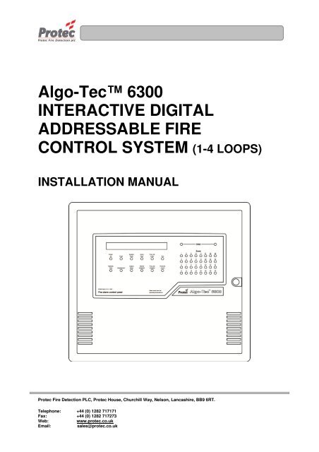
Algo-Tec <strong>6300</strong>INTERACTIVE DIGITALADDRESSABLE FIRECONTROL SYSTEM (1-4 LOOPS)INSTALLATION MANUAL<strong>Protec</strong> <strong>Fire</strong> <strong>Detection</strong> PLC, <strong>Protec</strong> House, Churchill Way, Nelson, Lancashire, BB9 6RT.Telephone: +44 (0) 1282 717171Fax: +44 (0) 1282 717273Web:www.protec.co.ukEmail:sales@protec.co.uk
Document Revision DetailsIssue Modification Detail Author Date1 Original Issue - 04/07/012 Revised Tables PWD 21/11/022aEnvironment Information, Battery TypeFuse Ratings & Cable TypePWD 17/12/032 Rev 2Added 6000PLUS devices to table 2Removed loop device PIDsPWD 14/05/102 Rev 3 Refer to ECN 3380 AH 28/06/1393-509-09 - Issue 2 Rev 3 Page 2 of 24 Copyright <strong>Protec</strong> <strong>Fire</strong> <strong>Detection</strong> PLC
INTRODUCTION ..................................................................................................................................... 51.1 THE <strong>6300</strong> SYSTEM ...................................................................................................................................... 51.2 ‘6000 SERIES’ LOOP ................................................................................................................................... 51.2.1 LOOP SHORT CIRCUIT OR LOOP INTERRUPTION ..................................................................... 61.2.2 DELAYS TO OUTPUTS ....................................................................................................................... 61.2.3 DOUBLE ADDRESSING ..................................................................................................................... 6CABLING ................................................................................................................................................ 72.1 POWER SUPPLY CABLING (REMOTE CHARGER ONLY) ................................................................... 72.2 NETWORK / SERIAL CABLING (RS485) .................................................................................................. 72.3 LOOP CABLING .......................................................................................................................................... 82.3.1 GUIDE TO LOOP CABLE CONDUCTOR SIZES (mm 2 ) .................................................................. 82.4 ALARM CABLING ...................................................................................................................................... 9TABLE 1 - CABLING, NUMBER OF CORES .................................................................................................. 9CURRENT CONSUMPTION ................................................................................................................. 103.1 PANEL CURRENT ..................................................................................................................................... 103.2 LOOP CURRENT ....................................................................................................................................... 10TABLE 2 – ADDRESSABLE ‘6000’ LOOP EQUIPMENT CURRENT DETAILS ........................................ 11TABLE 2B – ADDRESSABLE ‘6000’ LOOP EQUIPMENT CURRENT DETAILS CONTINUED................... 12TABLE 2C – ADDRESSABLE ‘6000’ LOOP EQUIPMENT CURRENT DETAILS CONTINUED................... 13TABLE 3 – ADDRESSABLE LOOP EQUIPMENT WITH AUXILIARY SUPPLY ...................................... 14CURRENT DETAILS ....................................................................................................................................... 14TABLE 4 – NON-ADDRESSABLE LOOP EQUIPMENT CURRENT DETAILS ......................................... 14INSTALLATION PROCEDURE ............................................................................................................ 154.1 CONTROL PANEL .................................................................................................................................... 154.2 FIELD EQUIPMENT .................................................................................................................................. 16CABLE TEST ........................................................................................................................................ 17CONNECTION ...................................................................................................................................... 186.1 CONTROL EQUIPMENT .......................................................................................................................... 186.2 FIELD EQUIPMENT .................................................................................................................................. 186.3 ALARM CIRCUITS ................................................................................................................................... 186.4 FIRE STATION OUTPUT .......................................................................................................................... 18COMMISSIONING REQUIREMENTS ................................................................................................... 19<strong>6300</strong> SPECIFICATION .......................................................................................................................... 20APPENDIX A ......................................................................................................................................... 2193-509-09 - Issue 2 Rev 3 Page 3 of 24 Copyright <strong>Protec</strong> <strong>Fire</strong> <strong>Detection</strong> PLC
0832 0832<strong>Protec</strong> <strong>Fire</strong> <strong>Detection</strong> plc, Nelson, Lancashire, England BB9 6RT <strong>Protec</strong> <strong>Fire</strong> <strong>Detection</strong> plc, Nelson, Lancashire, England BB9 6RT1111PFD-CPR-0007PFD-CPR-0008BS EN 54-2:1997+A1:2006BS EN 54-4:1997 + A1 + A2:20066301 <strong>Fire</strong> Alarm Control PanelControl / Indicating and Power Supply equipment for firedetection and fire alarm systems for buildingsControl & Indicating:Performance under fire conditions: PassResponse delay (response time to fire): PassOperational reliability: PassDurability of operational reliability, Temperature resistance: PassDurability of operational reliability, Vibration resistance: PassDurability of operational reliability, Electrical stability: PassDurability of operational reliability, Humidity resistance: PassPower supply:Performance of power supply: PassDurability of operational reliability, Temperature resistance: PassDurability of operational reliability, Vibration resistance: PassDurability of operational reliability, Electrical stability: PassDurability of operational reliability, Humidity resistance: PassBS EN 54-2:1997+A1:2006BS EN 54-4:1997 + A1 + A2:20066302 <strong>Fire</strong> Alarm Control PanelControl / Indicating and Power Supply equipment for fire detectionand fire alarm systems for buildingsControl & Indicating:Performance under fire conditions: PassResponse delay (response time to fire): PassOperational reliability: PassDurability of operational reliability, temperature resistance: PassDurability of operational reliability, temperature resistance: PassDurability of operational reliability, Electrical stability: PassDurability of operational reliability, temperature resistance: PassPerformance of power supply: PassOperational reliability: PassPower supply:Durability of operational reliability, temperature resistance: PassDurability of operational reliability, temperature resistance: PassDurability of operational reliability, Electrical stability: PassDurability of operational reliability, temperature resistance: Pass0832<strong>Protec</strong> <strong>Fire</strong> <strong>Detection</strong> plc, Nelson, Lancashire, England BB9 6RT11PFD-CPR-0009BS EN 54-2:1997+A1:2006BS EN 54-4:1997 + A1 + A2:20066304 <strong>Fire</strong> Alarm Control PanelControl / Indicating and Power Supply equipment for firedetection and fire alarm systems for buildingsControl & Indicating:Performance under fire conditions: PassResponse delay (response time to fire): PassOperational reliability: PassDurability of operational reliability, Temperature resistance: PassDurability of operational reliability, Vibration resistance: PassDurability of operational reliability, Electrical stability: PassDurability of operational reliability, Humidity resistance: PassPower supply:Performance of power supply: PassDurability of operational reliability, Temperature resistance: PassDurability of operational reliability, Vibration resistance: PassDurability of operational reliability, Electrical stability: PassDurability of operational reliability, Humidity resistance: Pass93-509-09 - Issue 2 Rev 3 Page 4 of 24 Copyright <strong>Protec</strong> <strong>Fire</strong> <strong>Detection</strong> PLC
INTRODUCTIONThis document describes the methods to be employed when installing and connecting equipment associated withthe PROTEC <strong>6300</strong> FIRE ALARM CONTROL PANEL. The <strong>6300</strong> panel is produced with 1, 2 or 4 loops and thismanual is suitable for all versions.1.1 THE <strong>6300</strong> SYSTEM(REFER TO PID 203 – <strong>6300</strong> Example System Diagram)Each addressable loop device has a unique Serial Number. The <strong>6300</strong> panel communicates with each device bythis Serial Number, and the device replies with an analogue value. This analogue value is interpreted by thepanel to determine the state of the device. The panel is therefore able to track accurately any changes in devicereply values and initiate any necessary actions.The <strong>6300</strong> panel can drive up to 4 loops, each containing a maximum of 191 devices. No more than 512 detectorsand manual call points, spread across all four loops, may be fitted in order to comply with En54. Each device canactuate an on-site-programmable set of outputs. 8 internal outputs are available (4 monitored, 2 non monitoredchangeover contacts, a monitored 24V fire station output and a non-monitored fault changeover contact). It isalso possible to have an output on any address point using ZONE/ALARM interface units and 16 Way I/OBoards.It is possible to network up to 31 panels/repeaters. Networked panels/repeaters use a separate network cardmounted on top of the terminal board. They are connected together using an RS485 loop (refer to PID 194).If networking is not used then a 4 core communication link (2 data + 2 power) can be used to provide an RS485serial link to a maximum of 4 repeat panels.1.2 ‘6000 SERIES’ LOOPEach <strong>6300</strong> has the capability to communicate with <strong>Protec</strong> ‘6000 Series’ loops.Each addressable loop device has a unique Serial Number. The <strong>6300</strong> panel communicates with each device bythis Serial Number and the device replies with an analogue value. This analogue value is interpreted by the panelto determine the state of the device. The panel is therefore able to track accurately any changes in device replyvalues and initiate any necessary actions.The installer must mark up on the ‘as fit’ drawings the panel number (if more than one), loop number andaddress of each device. This information will be required in section 6.2.93-509-09 - Issue 2 Rev 3 Page 5 of 24 Copyright <strong>Protec</strong> <strong>Fire</strong> <strong>Detection</strong> PLC
1.2.1 LOOP SHORT CIRCUIT OR LOOP INTERRUPTIONIt must not be possible to have a short circuit or interruption in the loop that prevents the indication of a firealarm from more than one zone. To comply with this instruction, the installer must fit at least one isolator perzone. The 6000 series loop has been designed with this in mind and so all addressable sounder bases,6000/MICCO and 6000/MCP devices have a built-in isolator. Check device literature for other devices with anisolator. If further isolators are required then loop isolator bases and loop isolation units are available (see table4).1.2.2 DELAYS TO OUTPUTSEn54-2:1997 + A1:2006 clause 7.11d states that it must be possible to override the delays and immediatelyaction the delayed outputs at access level one. Since access level one means that the outer panel door is lockedthen if delays are to be used this clause can be met in several ways. If option (3) is chosen then this will affectthe installation.1. No delays are programmed for manual call points.2. System programming permits a second activation to cancel delays and immediately activate outputs thusallowing any manual call point to be pressed upon confirmation of a fire.3. Programming at least one manual call point to activate all delayed outputs. This should be placed adjacent toeach <strong>6300</strong> panel and its purpose clearly labelled.1.2.3 DOUBLE ADDRESSING‘Double Addressing’, where a detection device and a sounder are assigned to the same address, is not supportedby the <strong>6300</strong> panel.93-509-09 - Issue 2 Rev 3 Page 6 of 24 Copyright <strong>Protec</strong> <strong>Fire</strong> <strong>Detection</strong> PLC
CABLINGAll external wiring associated with the system must conform to the current I.E.E Regulations and cabling mustconform to the relevant BS specifications. ECA recommended Cable Separation for ElectromagneticCompatibility in Buildings, must be followed.All cabling must be fully phased (Identify and mark ends of cables).Although no connections are to be made to the <strong>6300</strong> panel until the commissioning stage it is important thatcables are left long enough to connect directly to the relevant terminals. To ensure that cable tails are left withsufficient length all cable tails must be a minimum of 500mm. Locate the termination positions using ProductInformation Drawings: -PID 201 - <strong>6300</strong> TERMINAL BOARD CONNECTIONSPID 202 - <strong>6300</strong> REPEAT TERMINAL BOARD CONNECTIONS2.1 POWER SUPPLY CABLING (REMOTE CHARGER ONLY)If the <strong>6300</strong> panel has an external charger then it will require two separate +24V supplies. This is a requirement ofEn54-4 clause 6.4. These two supplies must not be wired in the same fire rated cable. In addition there is a faultsignal ‘SF’ from the charger to the panel and a charger inhibit signal ‘CI’ from the panel to the charger. Thesetwo signals can be combined with one of the +24V supplies into a 4-core fire rated cable.The maximum length of cable between the charger and the <strong>6300</strong> panel will depend upon the volt drop along thecable. No more than 3A must be supplied to a panel and no more than two panels must be fed from the samecharger.2.2 NETWORK / SERIAL CABLING (RS485)A <strong>6300</strong> panel requires the RS485 network to be wired as a loop. This is because the RS485 network is wired as aloop in order to continue to indicate a fire alarm from any device on the system should a single break or shortcircuit occur in one of the RS485 circuits.The maximum length of cable between any two <strong>6300</strong> panels on the RS485 network is 1km using a minimumstandard of 1.5mm 2 fire rated cable. The maximum length of the whole RS485 network loop is 5km.The maximum length of cable from the <strong>6300</strong> panel to all of the RS485 serial repeat panels is 1km using aminimum standard of 1.5mm 2 fire rated cable.In countries where local standards permit, the network can be wired in ‘Twin Figure 8’ cable but the cable lengthwill have to be reduced in accordance with the lower conductor size.EACH OF THE RS485 CIRCUITS MUST BE WIRED IN A SEPARATE PAIR. WHEN THE CABLE HAS ASCREEN THEN THE SCREEN MUST BE EARTHED AND CONTINUOUS OVER THE CABLE RUN.93-509-09 - Issue 2 Rev 3 Page 7 of 24 Copyright <strong>Protec</strong> <strong>Fire</strong> <strong>Detection</strong> PLC
2.3 LOOP CABLINGThe main consideration for the loop cable is the loop length. This length must include all sub-loops and spurs.For example, a loop of 800m with three spurs of 150m must be considered as being 1250m in length.Notes :-1. The loop cabling must be wired in fire rated cable. The minimum conductor size is shownin the tables of section 2.3.1. In countries where local standards permit, the loops can be wiredin ‘Twin Figure 8’ cable but the loop length and load will have to be reduced in accordancewith the lower conductor size.2. Maximum loop resistance = 16Ω per conductor.3. It is assumed that devices are evenly spread on the loop. If a large load, eg a number ofsounders, is located at the end of the loop then the volt drop along the cable must be calculatedto ensure that the input voltage to the loop devices remains within the range of 16 to 30V(peak).Each address point must be numbered. Sequential address allocation of devices on the loops is not necessarywith a <strong>6300</strong> system but it may prove advantageous for fault finding.EACH OF THE LOOPS MUST BE WIRED IN A SEPARATE PAIR. WHEN THE CABLE HAS A SCREEN THENTHE SCREEN MUST BE EARTHED AND CONTINUOUS OVER THE CABLE RUN.2.3.1 GUIDE TO LOOP CABLE CONDUCTOR SIZES (mm 2 )TotalLoopLoadinAlarm(mA)Loop Length (metres)500 550 600 650 700 750 800 850 900 950 100050 1.0 1.0 1.0 1.0 1.0 1.0 1.0 1.5 1.5 1.5 1.5100 1.0 1.0 1.0 1.0 1.0 1.0 1.0 1.5 1.5 1.5 1.5150 1.0 1.0 1.0 1.0 1.0 1.0 1.0 1.5 1.5 1.5 1.5200 1.0 1.0 1.0 1.0 1.0 1.0 1.0 1.5 1.5 1.5 1.5250 1.0 1.0 1.0 1.0 1.0 1.0 1.0 1.5 1.5 1.5 1.5300 1.0 1.0 1.0 1.0 1.0 1.0 1.0 1.5 1.5 1.5 1.5350 1.0 1.0 1.0 1.0 1.0 1.0 1.0 1.5 1.5 1.5 1.5400 1.0 1.0 1.0 1.0 1.0 1.0 1.0 1.5 1.5 1.5 1.5450 1.0 1.0 1.0 1.0 1.0 1.5 1.5 1.5 1.5 1.5 1.5500 1.0 1.0 1.0 1.0 1.5 1.5 1.5 1.5 1.5 1.5 2.5550 1.0 1.0 1.0 1.5 1.5 1.5 1.5 1.5 1.5 2.5 2.5600 1.0 1.0 1.5 1.5 1.5 1.5 1.5 2.5 2.5 2.5 2.5TotalLoopLoadinAlarm(mA)Loop Length (metres)1000 1050 1100 1150 1200 1250 1300 1350 1400 1450 150050 1.5 1.5 1.5 1.5 1.5 2.5 2.5 2.5 2.5 2.5 2.5100 1.5 1.5 1.5 1.5 1.5 2.5 2.5 2.5 2.5 2.5 2.5150 1.5 1.5 1.5 1.5 1.5 2.5 2.5 2.5 2.5 2.5 2.5200 1.5 1.5 1.5 1.5 1.5 2.5 2.5 2.5 2.5 2.5 2.5250 1.5 1.5 1.5 1.5 1.5 2.5 2.5 2.5 2.5 2.5 2.5300 1.5 1.5 1.5 1.5 1.5 2.5 2.5 2.5 2.5 2.5 2.5350 1.5 1.5 1.5 1.5 1.5 2.5 2.5 2.5 2.5 2.5 2.5400 1.5 1.5 1.5 1.5 1.5 2.5 2.5 2.5 2.5 2.5 2.5450 1.5 1.5 1.5 1.5 2.5 2.5 2.5 2.5 2.5 2.5 2.5500 2.5 2.5 2.5 2.5 2.5 2.5 2.5 2.5 2.5 2.5 N/A550 2.5 2.5 2.5 2.5 2.5 2.5 2.5 2.5 2.5 2.5 N/A600 2.5 2.5 2.5 2.5 2.5 2.5 2.5 2.5 N/A N/A N/A93-509-09 - Issue 2 Rev 3 Page 8 of 24 Copyright <strong>Protec</strong> <strong>Fire</strong> <strong>Detection</strong> PLC
2.4 ALARM CABLINGThe main consideration for the alarm cable is the length. This length must include all spurs. For example, analarm circuit of 800m with three spurs of 150m must be considered as being 1250m in length.Notes :-1. The alarm cabling must be wired in a minimum standard of 2.5mm 2 fire rated cable.2. If however, the total alarm cabling length is less than 1km, then the alarm circuit may bewired in a minimum standard of 1.5mm 2 fire rated cable. In countries where local standardspermit, the alarm circuit can be wired in ‘Twin Figure 8’ cable but the cable length and loadwill have to be reduced in accordance with the lower conductor size.3. The maximum permissible alarm circuit length is limited by volt drop.EACH OF THE ALARM CIRCUITS MUST BE WIRED IN A SEPARATE PAIR. WHEN THE CABLE HAS ASCREEN THEN THE SCREEN MUST BE EARTHED AND CONTINUOUS OVER THE CABLE RUN.TABLE 1 - CABLING, NUMBER OF CORESCABLE1. Supply 230 volts 50Hz2. Network DataRepeat Panel Data3. Loop CircuitAlarm Circuit4. Power Pair For: -Zone/Alarm Interface UnitsI/O Interface UnitsRepeat Panel Power SupplyNumber of Cores3222 (per loop)2 (per circuit)222Remote Chargers Only5. 24V Supply circuit 124V Supply circuit 2SF & CI Signals22293-509-09 - Issue 2 Rev 3 Page 9 of 24 Copyright <strong>Protec</strong> <strong>Fire</strong> <strong>Detection</strong> PLC
CURRENTCONSUMPTIONIt is necessary to calculate current consumption figures for the system in standby (mains fail) and alarmconditions in order to select the correct battery capacity.3.1 PANEL CURRENTDetails of panel currents for standby and alarm are shown in the <strong>6300</strong> specification later in this manual.3.2 LOOP CURRENTFigures for the loop device current for battery capacity calculations are contained in tables 2, 3 and 4. Theseprovide details of the quiescent and alarm currents of both the addressable and non-addressable loop devices.Note: -1. Loop isolators, devices that isolate sections of the loop if short circuit wiring faults occur, are availableas separate units. Some ‘6000 series’ devices contain an isolator. Check device literature.2. When using Zone interfaces the current per detector / sounder must be added to the current requirementof the Interface Units (refer to note 2 of table 3).3. The alarm loop current figures may differ from the figures quoted in other <strong>Protec</strong> literature. The figureshere assume a limit on the number of devices lighting their fire led so this reduced led current isaveraged across all the loop devices.93-509-09 - Issue 2 Rev 3 Page 10 of 24 Copyright <strong>Protec</strong> <strong>Fire</strong> <strong>Detection</strong> PLC
TABLE 2 – ADDRESSABLE ‘6000’ LOOP EQUIPMENT CURRENT DETAILSADDRESSABLE DEVICESOPTICAL SMOKE DETECTOR6000/OPOPTICAL HEAT SMOKE DETECTOR6000/OPHTTEMPERATURE DETECTOR6000/TEMPOPTICAL HEAT CO SMOKE DETECTOR6000/OP/HT/COCO HEAT DETECTOR6000/HT/COIONISATION SMOKE DETECTOR6000/IONBREAK GLASS6000/MCPSOUNDER BASE6000/ASB2SOUNDER BASE WITH FLASHINGXENON BEACON - 6000/ASBEA2RED SYMPHONY SOUNDER6000/SYM2RSOUNDER6000/SSR2SOUNDER6000/SRZ2BEACON6000/PVR2SOUNDER XENON BEACON6000/SRZ2/PVRMONITORED INPUT CLEAN CONTACTOUTPUT BOARD - 6000/MICCOCLEAN CONTACT OUTPUT BOARD6000/CCOMONITORED INPUT BOARD6000/MIPMONITORED INPUT WITH CLEANCONTACT OUTPUT - 6000/MIPCCOQUIESCENTLOOP CURRENT(mA)ALARMLOOP CURRENT(mA)0.35 0.550.35 0.550.35 0.550.45 0.650.35 0.550.52 0.820.5 0.850.6 60.6 100.5 50.65 50.5 200.545 (Xenon)5 Av / 12 pk (LED)0.5 751.3 50.6 100.65 40.7 1593-509-09 - Issue 2 Rev 3 Page 11 of 24 Copyright <strong>Protec</strong> <strong>Fire</strong> <strong>Detection</strong> PLC
TABLE 2b – ADDRESSABLE ‘6000’ LOOP EQUIPMENT CURRENT DETAILS continuedADDRESSABLE DEVICESQUIESCENTLOOP CURRENT(mA)ALARMLOOP CURRENT(mA)6000Plus Optical Detector 0.2 0.556000Plus Heat Detector 0.2 0.556000Plus Optical Heat Detector 0.2 0.556000Plus Optical Heat Detector with Isolator 0.4 2.536000Plus Optical Heat Detector with Sounder 0.4 9.236000Plus Optical Heat Detector with Sounderand LED Beacon6000Plus Optical Heat Detector with TalkingSounder6000Plus Optical Heat Detector with TalkingSounder and LED Beacon6000Plus Optical Heat Detector with LEDBeacon0.4 14.230.4 12.530.4 17.530.4 7.536000Plus Optical Heat CO Detector 0.45 0.656000Plus Optical Heat CO Detector withSounder6000Plus Optical Heat CO Detector withSounder and LED Beacon6000Plus Optical Heat CO Detector withTalking Sounder and LED Beacon6000Plus Optical Heat CO Detector with LEDBeacon0.45 9.280.45 14.280.45 17.580.45 7.66000Plus Optical Detector with Sounder 0.4 9.236000Plus Heat Detector with LED Beacon 0.4 7.536000Plus Heat Detector with Sounder 0.4 9.236000Plus Heat Detector with Sounder andLED Beacon6000Plus Heat Detector with Talking Sounderand LED Beacon0.4 14.230.4 17.536000Plus Talking SSR 0.4 9.46000Plus Talking SSR with LED Beacon 0.45 14.4293-509-09 - Issue 2 Rev 3 Page 12 of 24 Copyright <strong>Protec</strong> <strong>Fire</strong> <strong>Detection</strong> PLC
TABLE 2c – ADDRESSABLE ‘6000’ LOOP EQUIPMENT CURRENT DETAILS continuedADDRESSABLE DEVICESLOOP BEAM DETECTOR6000/BEAM – (MIP)TALKING SOUNDER BASE6000/ATSB26400 LOOP LCDCIRRUS PRO INTERFACE6000/CPROQUIESCENTLOOP CURRENT(mA)ALARMLOOP CURRENT(mA)0.65 70.7 17 (Bell tone)86 (No disablement) 193 av. (+Disablement)96 pk98 (No disablement) 1101av. (+Disablement)103pk10 10LOCAL CONTROL MODULE 0.7 + detectors + EOL 67mA1 Figure assumes a supply fault, buzzer on and both LCD backlights on93-509-09 - Issue 2 Rev 3 Page 13 of 24 Copyright <strong>Protec</strong> <strong>Fire</strong> <strong>Detection</strong> PLC
TABLE 3 – ADDRESSABLE LOOP EQUIPMENT WITH AUXILIARY SUPPLYCURRENT DETAILSADDRESSABLE DEVICES QUIESCENT (mA) ALARM (mA)LOOP ADDRESSED SOUNDER BASEWITH AUXILIARY SUPPLY(6000/ASB4)LOOP ADDRESSED SOUNDER BASEWITH FLASHING BEACON (AUXILIARYSUPPLY)(6000/ASBEA4)LOOP ADDRESSED SOUNDER WITHAUXILIARY SUPPLY6000/SRZ4LOOP ADDRESSED BEACON WITHAUXILIARY SUPPLY6000/PVR4LOOP ADDRESSED SOUNDER BEACONWITH AUXILIARY SUPPLY6000/SRZ4/PVRZONE ALARM INTERFACE6000/ZALOOP 24V LOOP 24V0.58 - 1.5 80.58 - 1.5 25 average80 peak 10.5 - 2 200.5 - 2 450.5 - 2 7516 WAY INTERFACE7 18 + zone load6000/16WAY 2 + output boardload (5A max)0.6 4 + zone load 4 35 + alarm load(1A max)7 18 + zone load +output board load(5A max)TABLE 4 – NON-ADDRESSABLE LOOP EQUIPMENT CURRENT DETAILSNON-ADDRESSABLE DEVICE QUIESCENT (mA) ALARM (mA)24V SOUNDER BASE(6000/SB)24V SOUNDER BASE WITH BEACON(6000/SBEA)FLUSH ISOLATOR UNIT6000/FIUBOXED ISOLATOR UNIT6000/IUDUAL ISOLATOR BASE6000/DIBSTANDARD BASE6000/BASERELAY BASE6000/RBNC or 6000/RBNOLOOP 24V LOOP 24V- - - 7- - - 25 average80 peak 10.12 - 0.12 -0.12 - 0.12 -0.12 - 0.12 -- - - -0.05 - 15 -1 The peak values occur when the beacon is at its ‘on’ stage during flashing.2 There are variants of this product depending upon the monitoring requirements.93-509-09 - Issue 2 Rev 3 Page 14 of 24 Copyright <strong>Protec</strong> <strong>Fire</strong> <strong>Detection</strong> PLC
INSTALLATIONPROCEDURE4.1 CONTROL PANELThe <strong>6300</strong> is supplied complete and fully assembled in one box. The box also contains an installation templateshowing mounting hole & cable entry positions with spirit level and plumb bob references.1) Unpacking.Remove the installation template from the packaging - leaving the <strong>6300</strong> unit in the box for protection.2) Preparing the Mounting Position.Use the installation template together with a spirit level etc. to mark, drill and plug the 3 mounting holes in thedesired position.3) Removal of the Plastic Door.Remove the <strong>6300</strong> unit from the packaging. Use the key supplied to unlock the outer plastic door, remove theplastic door by extracting the hinge pins and place the door back in the box for protection.4) Removal of the Inner Door.Unscrew the 3 fixings on the metal inner door at the lock side of the door. Open the inner door and disconnectthe earthing point on the door and the wide ribbon cable that connects the main board on the door to the back ofthe enclosure. Close the door and extract the 2 remaining hinge pins. Carefully remove the inner door from theunit including all circuit boards fitted to it and place it back in the box for protection.5) Removal of the battery clamp and gear-tray.Remove the two screws holding the battery clamp (if supplied) and carefully withdraw the clamp ensuring that itcannot short out the battery terminals. Remove the 2 screws from the bottom of the gear-tray (in the back of theenclosure) and loosen the two at the top (key-hole fixings). Disconnect the earth connection from the gear-tray tothe enclosure. Remove the gear-tray from the enclosure including the attached circuit boards.6) Preparing and Fixing The Unit.Using the installation template, mark out suitable positions for cable entry on the back of the enclosure i.e. notbehind the gear-tray. Cut out the cable entry positions and mount the enclosure at the position prepared in (2)feeding cables through into the box.7) Re-fitting the gear-tray and battery clampRe-fit the gear tray (re-fit is reversal of 5). Ensure that the earth removed in (5) is re-connected DO NOTCONNECT ANY NON-EARTH TERMINALS. Refit the battery clamp (refit is reversal of 5) ensuring thatthe clamp cannot touch the battery terminals. DO NOT CONNECT THE BATTERIES8) Re-fitting the Inner DoorRe-fit the inner door (re-fit is reversal of 4) ENSURE THAT ALL EARTHING POINTS ARE RE-CONNECTED.9) Re-fitting the Plastic DoorRe-fit the outer plastic door by offering the door up to the hinges and inserting the 2 hinge pins.93-509-09 - Issue 2 Rev 3 Page 15 of 24 Copyright <strong>Protec</strong> <strong>Fire</strong> <strong>Detection</strong> PLC
4.2 FIELD EQUIPMENTAll metal termination boxes and detector bases should be securely fastened to the mounting surface and earthbonded.FIELD EQUIPMENT MUST NOT BE CONNECTED AT THIS STAGE.93-509-09 - Issue 2 Rev 3 Page 16 of 24 Copyright <strong>Protec</strong> <strong>Fire</strong> <strong>Detection</strong> PLC
CABLE TESTBefore connecting external cables to any field device, tests must be carried out using a 500V DC insulation tester(Megger). The readings between each cable core, and each core and earth must be greater than 10M ohms(record the readings). Equipment connected to the cabling during insulation tests could be damaged with the highvoltages produced. Great care must be taken during insulation tests to discharge the cables, since charged cablemay damage the control equipment upon connection.93-509-09 - Issue 2 Rev 3 Page 17 of 24 Copyright <strong>Protec</strong> <strong>Fire</strong> <strong>Detection</strong> PLC
CONNECTIONFor general wiring details see Product Information Drawings - see ‘REFERENCES’ section.6.1 CONTROL EQUIPMENTWiring details are supplied for reference only. DO NOT MAKE ANY CONNECTIONS TO THE CONTROLPANEL.6.2 FIELD EQUIPMENTIn order to perform the commissioning of devices correctly, the following procedure needs to be carried out uponinstallation of each addressable loop device: -• Remove one of the unique Serial Number bar code labels.• Place this label at the chosen Node, Loop and Address position in the ‘Commissioning Booklet’provided. (The address position was defined in section 1).With reference to the relevant connection diagrams, connect the remaining field equipment. Note: Insulationtests MUST NOT be carried out after this point and the mains or standby supply MUST NOT be connected.6.3 ALARM CIRCUITSEach of the four alarm circuits requires a 10K end-of-line resistor for open and short circuit monitoring.6.4 FIRE STATION OUTPUTThis output is the ‘Output to <strong>Fire</strong> Alarm Routing Equipment’ defined by En54.It is designed to drive 24V into an 1100Ω load. This output is open and short circuit monitored by the use of a1K 0.5W end-of-line resistor.93-509-09 - Issue 2 Rev 3 Page 18 of 24 Copyright <strong>Protec</strong> <strong>Fire</strong> <strong>Detection</strong> PLC
COMMISSIONINGREQUIREMENTSRefer to the supplied copy of COMMISSIONING STANDARD TERMS for details of requirements beforecommissioning can take place.Note: The <strong>Fire</strong> Alarm Commissioning Application form must be completed and returned 14 days before acommissioning engineer can attend.93-509-09 - Issue 2 Rev 3 Page 19 of 24 Copyright <strong>Protec</strong> <strong>Fire</strong> <strong>Detection</strong> PLC
<strong>6300</strong> SPECIFICATIONPOWER SUPPLY MAINS 230V AC Nominal ± 10% ( T1A 250V HBC Fuse )WORKING VOLTAGECURRENT CONSUMPTIONMAXIMUM LOOP CURRENTANALOGUE ADDRESSES21.5 - 30V DC180mA WITHOUT LOOP LOAD @ 24V DCMAINS FAILED, PRINTER STATIONARY600mA per loop4 LOOPS, 191 ADDRESSES PER LOOP(Maximum of 512 Detectors and <strong>Manual</strong> Call Points to comply with En54)ZONES 32ALARM OUTPUTS i) 4 MONITORED 24V DC ( T1A 250V FUSES )ii) 2 NON MONITORED - (CONTACTS 1A RATED @ 24V DC)iii) LOOP ADDRESSABLE OUTPUT DEVICES, SUBJECT TO THEFOLLOWING PARAMETERS NOT BEING EXCEEDED: -THE MAXIMUM NUMBER OF DEVICES PER LOOPTHE MAXIMUM LOOP LENGTHTHE MAXIMUM LOOP CURRENT.MAXIMUM ALARM LOADFIRE STATION OUTPUTFAULT OUTPUTSERIAL COMMUNICATIONSNETWORKINTEGRAL CHARGERINTEGRAL BATTERIES(Lynteck OL Models)3A WITH INTEGRAL POWER UNIT (INCLUDING LOOP CURRENTAND INTERNAL PANEL CONSUMPTION).MONITORED 24V DC OUTPUT RATED @ 20mA maxSINGLE POLE CHANGEOVER CONTACTS - (1A RATED @ 24V DC)2 WIRE RS485 COMMS + 2 WIRE POWER2 WIRE RS485 LOOP3A SWITCH MODE (<strong>Protec</strong> series 9000 PSU)4 x 6V 10Ah Sealed lead acid2 x 12V 26Ah Sealed lead acid (when using the external battery boxmounted beneath the panel)AUXILIARY 24V OUTPUT 24V DC ( F1A 250V FUSE )INTERNAL PRINTER SUPPLY 24V DC ( F1A 250V FUSE )TEMPERATURE RANGEHUMIDITY LIMITENVIRONMENTDIMENSIONSENCLOSUREMOUNTING0-40°C85% NON-CONDENSINGThe <strong>6300</strong> meets IP30. It must be mounted in a dry position that does notexceed the temperature or humidity limits specified above.385(H) x 440(W) x 145(D)Storm grey textured enclosure smooth inner door with molded v-ratedpolycarbonate lockable front door3 points surface mount93-509-09 - Issue 2 Rev 3 Page 20 of 24 Copyright <strong>Protec</strong> <strong>Fire</strong> <strong>Detection</strong> PLC
APPENDIX AThe following Product Information Drawings (PIDs) are attached :-PID 194 - <strong>6300</strong> Network connectionsPID 201 - <strong>6300</strong> Terminal Board ConnectionsPID 202 - <strong>6300</strong> Repeat Terminal Board ConnectionsPID 203 - <strong>6300</strong> Example System DiagramPIDs for loop devices are supplied with the individual products and also available from the websitewww.protec.co.ukIf in doubt contact <strong>Protec</strong> <strong>Fire</strong> <strong>Detection</strong> plc.93-509-09 - Issue 2 Rev 3 Page 21 of 24 Copyright <strong>Protec</strong> <strong>Fire</strong> <strong>Detection</strong> PLC
BLANK PAGE93-509-09 - Issue 2 Rev 3 Page 22 of 24 Copyright <strong>Protec</strong> <strong>Fire</strong> <strong>Detection</strong> PLC
BLANK PAGE93-509-09 - Issue 2 Rev 3 Page 23 of 24 Copyright <strong>Protec</strong> <strong>Fire</strong> <strong>Detection</strong> PLC
<strong>Protec</strong> <strong>Fire</strong> <strong>Detection</strong> PLC, <strong>Protec</strong> House, Churchill Way, Nelson, Lancashire, BB9 6RT.Telephone: +44 (0) 1282 717171Fax: +44 (0) 1282 717273Web: www.protec.co.ukEmail: sales@protec.co.uk93-509-09 - Issue 2 Rev 3 Page 24 of 24 Copyright <strong>Protec</strong> <strong>Fire</strong> <strong>Detection</strong> PLC