6400 Operating Manual - Protec Fire Detection
6400 Operating Manual - Protec Fire Detection
6400 Operating Manual - Protec Fire Detection
- No tags were found...

Create successful ePaper yourself
Turn your PDF publications into a flip-book with our unique Google optimized e-Paper software.
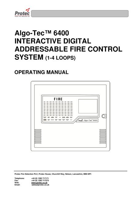
Algo-Tec <strong>6400</strong>INTERACTIVE DIGITALADDRESSABLE FIRE CONTROLSYSTEM (1-4 LOOPS)OPERATING MANUAL<strong>Protec</strong> <strong>Fire</strong> <strong>Detection</strong> PLC, <strong>Protec</strong> House, Churchill Way, Nelson, Lancashire, BB9 6RT.Telephone: +44 (0) 1282 717171Fax: +44 (0) 1282 717273Web:www.protec.co.ukEmail:sales@protec.co.uk
<strong>6400</strong> OPERATING MANUALISSUESISSUE DATE RELEASED DETAILS OF CHANGE AUTHOR4 Rev 3 April 2005 Screen shots updated and other minor changes K.Z.4 Rev 4 September 20064 Rev 5 April 20074 Rev 6 April 20095 September 2010Updated section 4.1 (Advanced Options)Updated section 6.1 (<strong>Fire</strong> Alarm Count)Updated section 8.2 (DSZ & DSG status)Updated section 10.1 (View / Edit)Updated section 13.3 (Low & high sensitivity)Added section 26 (Loop LCD Panel)Several screen shots updatedRemoved section 1.5Added section 8.5.2 (Fault Link)Changed ‘Device Disabled’ led to ‘Disablement’Added section 8.7 (Output Delay Disablement)Several screen shots updatedPage 10, Replaced references to BreakglassUnit with MCPScreen shots updatedAdded information on disabling all the deviceswithin a zoneRemoved section 8.7 (Output Delay Disablement)PDPDPDPDNotes1) This manual covers 4400, 5400 and <strong>6400</strong> systems. The differences are described in theappropriate sections.2) This manual covers <strong>Fire</strong> and General Alarm systems. The differences are described in theappropriate sections.93-310-10 Issue 5 Page 2 of 86 Copyright <strong>Protec</strong> <strong>Fire</strong> <strong>Detection</strong> PLC
<strong>6400</strong> OPERATING MANUALCONTENTSOVERVIEW .................................................................................................................................................................... 51.1 <strong>6400</strong> NETWORK OVERVIEW .......................................................................................................................... 51.2 <strong>6400</strong> NODE DESCRIPTIONS ............................................................................................................................ 61.3 DCN NODE ........................................................................................................................................................ 61.4 LPN NODE ......................................................................................................................................................... 6DCN FUNCTIONS ......................................................................................................................................................... 72.1 NORMAL DISPLAY .......................................................................................................................................... 72.2 VIEWING FIRE / ALARM EVENTS .............................................................................................................. 82.2.1 MULTIPLE DEVICES IN ALARM ............................................................................................................ 92.2.2 GENERAL ALARM .................................................................................................................................... 92.3 PRINTING FIRE EVENTS ............................................................................................................................... 102.4 SILENCING FIRE EVENTS ........................................................................................................................ 102.5 SOUND ALARMS ............................................................................................................................................ 112.6 RESETTING FIRE EVENTS ........................................................................................................................... 112.7 DISPLAY OF FAULT EVENTS ...................................................................................................................... 112.7.1 VIEWING FAULT EVENT DETAILS. .................................................................................................... 122.7.2 MUTING THE ‘FAULT’ BUZZER .......................................................................................................... 122.8 DISPLAY OF DISABLEMENTS ................................................................................................................... 132.8.1 VIEWING DISABLEMENT DETAILS .................................................................................................. 142.8.2 MUTING THE ‘DISABLEMENT’ BUZZER ........................................................................................... 14ROUTINE ATTENTION .............................................................................................................................................. 153.1 RESPONSIBLE USER ...................................................................................................................................... 153.2 ROUTINE TESTS .............................................................................................................................................. 15USER MENU ACCESS ................................................................................................................................................ 164.1 MENU ACCESS ............................................................................................................................................... 16SET TIME & DATE ..................................................................................................................................................... 185.1 SET TIME & DATE. ........................................................................................................................................ 185.2 SETTING THE DATE ...................................................................................................................................... 195.3 SETTING THE TIME ....................................................................................................................................... 21DISPLAY EVENTS ...................................................................................................................................................... 226.1 DISPLAY EVENTS. ......................................................................................................................................... 226.2 DISPLAY PAST FIRES. ................................................................................................................................... 236.3 DISPLAY PAST FAULTS. .............................................................................................................................. 24PRINTER MENU .......................................................................................................................................................... 257.1 PRINTER MENU .............................................................................................................................................. 257.2 PRINT CURRENT FAULTS ............................................................................................................................ 267.3 PRINT CURRENT DISABLEMENTS ............................................................................................................. 277.4 PRINT PAST EVENTS..................................................................................................................................... 287.4.1 PRINT PAST FIRES / ALARMS .............................................................................................................. 297.4.2 PRINT PAST FAULTS .............................................................................................................................. 297.4.3 PRINT PAST DISABLEMENTS ............................................................................................................... 307.4.4 PRINT PAST OTHER EVENTS ............................................................................................................... 307.5 PRINT ANALOGUE VALUES ........................................................................................................................ 317.6 PRINT ADDRESS S/N ..................................................................................................................................... 327.7 PRINT HIGH NALOGUE VALUES ................................................................................................................ 337.8 CANCEL PRINTING ....................................................................................................................................... 33DISABLEMENT MENU .............................................................................................................................................. 348.1 DISABLEMENT MENU .................................................................................................................................. 348.2 DEVICE DISABLE / NORMALISE ................................................................................................................ 358.3 DISABLEMENTS TO VIEW ........................................................................................................................... 398.4 ZONE DISABLE / NORMALISE .................................................................................................................... 418.5 OUTPUT DISABLEMENT MENU .................................................................................................................. 438.5.1 DISABLE / ENABLE FIRE LINK ........................................................................................................ 438.5.2 DISABLE / ENABLE FAULT LINK ........................................................................................................ 448.5.3 DISABLE / ENABLE ALARM OUTPUTS .............................................................................................. 4593-310-10 Issue 5 Page 3 of 86 Copyright <strong>Protec</strong> <strong>Fire</strong> <strong>Detection</strong> PLC
<strong>6400</strong> OPERATING MANUALOVERVIEW1.1 <strong>6400</strong> NETWORK OVERVIEW<strong>6400</strong> PSUTo supply DCN<strong>6400</strong> DCN nodeHas FULL display and control ofthe network<strong>6400</strong> LPNcan drive up to 4 loops of127 devices(508 devices)in total<strong>6400</strong> LPNcan drive up to8 sounder circuits6 aux contacts24 volt supply to LCDscan be taken from thenode PSU or a separatePSU can be installed.Zone expansion if greaterthan 100 zones<strong>6400</strong> Network LCD (Listen)Has full LCD display. NO printerand NO control of the network.Can be a spur off the network<strong>6400</strong> LPN nodeDrives field wiringNO control of network<strong>6400</strong> PSUTo supply LPN<strong>6400</strong> LPNcan drive up to 4 loops of 127devices (508 devices) in total, 8sounder circuits and 6 aux contacts<strong>6400</strong> RDN NodeHas full LCD displaywith (optional printer).Limited control of the network<strong>6400</strong> DCN & LPNDrives field wiring & has FULLcontrol of the network<strong>6400</strong> PSUTo supply LPN<strong>6400</strong> DCN nodeHas FULL display and controlof the networkPC or Lap-topCan be connected toany <strong>6400</strong> DCN on thenetwork2 RS232 Portsused to connect a PC toprogram the network andoperate a ‘graphics’, ‘pager’or ‘BMS’ system.KEYSecure network (RS485)24 volt supply from PSU to node.LPN = Loop processing NodeDCN = Display control Node.RDN = Repeat display NodeLCD = Network LCD repeater.PSU = Power supply unit.93-310-10 Issue 5 Page 5 of 86 Copyright <strong>Protec</strong> <strong>Fire</strong> <strong>Detection</strong> PLC
<strong>6400</strong> OPERATING MANUAL1.2 <strong>6400</strong> NODE DESCRIPTIONS1.3 DCN NODELED DisplayLCD DisplayFIGURE 1Printer OutputControl ButtonsQWERTY Keypad Arrow keys Numeric KeypadSOUND ALARMSSILENCEACCEPTPressing this button will operate ‘Alarm outputs’ on the network as programmed when the system wascommissioned.Pressing this button will Silence ALL ‘Alarm outputs’ on the network.Pressing this button will accept any fire / fault events , and mute the fault buzzer.RESET Pressing this button will reset ALL fire indications , and release any ‘Control outputs’ .1.4 LPN NODEStatus LEDsDoor LockFIGURE 2 - Loop Processing Node (LPN)93-310-10 Issue 5 Page 6 of 86 Copyright <strong>Protec</strong> <strong>Fire</strong> <strong>Detection</strong> PLC
<strong>6400</strong> OPERATING MANUALDCN FUNCTIONS2.1 NORMAL DISPLAYThe following screen will be displayed when the system is in a ‘Normal’ condition (ie nofires, faults or disablements) :-Print Pending Icon(see section 2.3)• Logo : If there are no faults or disablements present then the box and highlight bar shown aboveare replaced by the logo. Pressing ‘0’ or ‘Esc’ removes the logo.93-310-10 Issue 5 Page 7 of 86 Copyright <strong>Protec</strong> <strong>Fire</strong> <strong>Detection</strong> PLC
<strong>6400</strong> OPERATING MANUAL2.2 VIEWING FIRE / ALARM EVENTSFIRE SIGNALOn hearing the ‘FIRE ALARM’ signal :-a) Evacuate the premises IMMEDIATELY.b) Send for the fire brigade.c) DO NOT re-enter the premises until authorised by the fire brigade.In the event of a fire activation occurring, the panel’s audible buzzer will fast pip. The ‘FIRE‘ lamp will illuminateconstantly and the ‘ZONE’ location lamp will illuminate intermittently. The panel will also display the location detailson the LCD display as follows :-Displays the Node /Loop / address and typeof the device in alarmNote - If text has beenassigned to the node,then the text will bedisplayed rather than thenode & loop NoDisplays the numberof Devices which arecurrently in an alarmconditionDisplays the ‘Zone’number in which the firehas occurredThe arrow indicates thesensor that has generatedthe fire signal.Displays the date &time of the activationDisplays the number offault events currently onthe systemDisplays the number ofdisablements currentlyon the system• Accept : Pressing the ‘Accept’ button will mute the panel buzzer. The buzzer will resound upon a furtheractivation. If a search time has been set up when the system was installed then pressing this buttonwill also start the search time.• Menus : Pressing the ‘ENTER’ button will display the normal menu options, which will allow access to the‘Main menu‘ or allow the display of any fault or disablements currently on the system as shownbelow :-• Exiting option : To return to the ‘FIRE’ display, press the ‘Esc’ key93-310-10 Issue 5 Page 8 of 86 Copyright <strong>Protec</strong> <strong>Fire</strong> <strong>Detection</strong> PLC
<strong>6400</strong> OPERATING MANUAL2.2.1 MULTIPLE DEVICES IN ALARMIn the event of more than one device producing a fire condition, the display will show the following :-Displays the Node /Loop / address and typeof the device in alarmNote - If text has beenassigned to the node,then the text will bedisplayed rather than thenode & loop NoDisplays the ‘Zone’number in which the firehas occurredDisplays the date &time of the activationDisplays the numberof Devices which arecurrently in an alarmconditionDisplays the number offault events currently onthe systemPressing the → key will scroll the display to show the description of each device in an alarm condition.Displays the number ofdisablements currentlyon the system2.2.2 GENERAL ALARMThe <strong>6400</strong> system is also used to display General Alarms. If the system is a General Alarm one then the ‘ALARM’ ledand the zone led will illuminate but if the system is a <strong>Fire</strong> Alarm one then these two leds will not illuminate to preventconfusion with a fire signal. The display of a general alarm is shown below :-Displays the Node /Loop / address and typeof the device in alarmGeneral AlarmNote - If text has beenassigned to the node,then the text will bedisplayed rather than thenode & loop No93-310-10 Issue 5 Page 9 of 86 Copyright <strong>Protec</strong> <strong>Fire</strong> <strong>Detection</strong> PLC
<strong>6400</strong> OPERATING MANUAL2.3 PRINTING FIRE EVENTSThe <strong>6400</strong> control panel will NOT print ‘<strong>Fire</strong>’ events automatically, they are printed on demand. If the panel has anyevents pending, the ‘Print Pending Icon’ will be shown on the top right corner of the LCD Display (see section 2.1).To print these events press and hold the ‘ Fn’ key and then press the ‘p’ key on the QWERTY keypad. This will printany fire events which have occurred in the following format :-Up to 60 characters of location text &up to 60 characters of alarm text(optional)The fire ZONE where the device hasactivatedLocation of device****************************List of pending fires / alarms22 Jan 2010, 10:05:22****************************Location textAlarm textTime 22 Jan 2010, 09:17:15<strong>Fire</strong> in zone 1Node 2 Loop 2 Address 14 Type****************************The Date & time the ‘List ofpending fires’ was printedThe time & date the fire event occurredOn the completion of printing all the events, the ‘PRINT’ Icon will extinguish and the printer will stop printing.To cancel printing at any time, press and hold the ‘Fn’ key and then press the ‘c’ key on the QWERTY keypad.This will stop the print-out.2.4 SILENCING FIRE EVENTSPressing the ‘SILENCE’ key after any FIRE event will cause the ‘ALARMS SILENCED’ led to illuminate or theSilence logo to appear at the top left of the LCD and the alarms to silence. The fast pip is an indication that theexternal alarm outputs are activated. DO NOT at this stage attempt to ‘RESET’ the system until the cause of the firehas been established.If the Red LED (Light) isilluminated constantly on thesmoke sensor, it means thatthis device has activated.If the Red LED (Light) isilluminated on the MCP, thedevice has been activated.If it has been activated thenreset it in accordance withthe instructions suppliedwith the device.SMOKE / HEAT SENSORMANUAL CALL POINT (MCP)The Alarms can be resounded at any time by pressing the ‘Sound alarms’ button (refer to section 2.5 for details).<strong>Manual</strong> call points must be physically reset. Automatic sensors must be visually checked to determine the operatedsensor. Further fire signals from other addresses will automatically re-sound the alarms (according to the cause &effects of the site).93-310-10 Issue 5 Page 10 of 86 Copyright <strong>Protec</strong> <strong>Fire</strong> <strong>Detection</strong> PLC
<strong>6400</strong> OPERATING MANUAL2.5 SOUND ALARMSPre-programmed Alarm Outputs may be sounded by pressing the ‘Sound alarms’ button (red).This will illuminate the ‘Alarms On’ LED, the buzzer will fast pip and the screen will display the following :-Indicates alarms are onTo silence the alarms, press the ‘Silence’ control button. This will extinguish the ‘Alarms On’ LED , stop the soundersand mute the panel buzzer. The display will also return to ‘System status : Normal’.2.6 RESETTING FIRE EVENTSAfter ‘silencing alarms’ (Section 2.4) and establishing the cause of the fire :-a) Press the ‘RESET’ button.Any fire indications will be extinguished.Any plant equipment (control outputs) will be reset.The fire condition will re-start if an automatic detector or manual call point remains active.2.7 DISPLAY OF FAULT EVENTSIn the event of a fault appearing on the system the panel buzzer will sound intermittently, and the ‘FAULT’ LED willilluminate. The LCD will also display the number of faults to view, as shown below :-Indicates the system is in afault statusDisplays the number offaults currently on thesystem.93-310-10 Issue 5 Page 11 of 86 Copyright <strong>Protec</strong> <strong>Fire</strong> <strong>Detection</strong> PLC
<strong>6400</strong> OPERATING MANUAL2.7.1 VIEWING FAULT EVENT DETAILS.• Selecting option : To view the current fault events move the highlight bar using the ‘arrow keys’ onto the ‘Xfaults to view’ (as shown in section 2.7 ), and then press the ‘ENTER’ button, this will thenprompt the following display indicating the current fault events on the system :-Indicates the system is in afault conditionDisplays the fault descriptionDisplays the location text ofthe fault (only displayed forcertain events)Displays the date and time whenthe fault event occurred• Other faults : Press ← or → to view other fault events.• Exiting option : To EXIT ‘viewing the fault events’ press the ‘ESC’ button . This will return to thenormal screen options (see section 2.7).2.7.2 MUTING THE ‘FAULT’ BUZZERTo mute the panel buzzer, press the ‘ACCEPT’ button. This will mute the panel buzzer. In the event of a further faultoccurring, the buzzer will resound and the ‘X faults to view’ will increment.93-310-10 Issue 5 Page 12 of 86 Copyright <strong>Protec</strong> <strong>Fire</strong> <strong>Detection</strong> PLC
<strong>6400</strong> OPERATING MANUAL2.8 DISPLAY OF DISABLEMENTSIn the event of a device being disabled on the system the panel buzzer will sound intermittently and the ‘Disablement’LED will illuminate. The LCD will also display the number of disablements to view :-Displays the number ofdisablements currentlyon the system93-310-10 Issue 5 Page 13 of 86 Copyright <strong>Protec</strong> <strong>Fire</strong> <strong>Detection</strong> PLC
<strong>6400</strong> OPERATING MANUAL2.8.1 VIEWING DISABLEMENT DETAILS• Selecting option : To view the current disablements move the highlight bar using the ‘arrow keys’ onto the‘X disablements to view’ (as shown above), and then press the ‘ENTER’ button. This willthen prompt the following display indicating the current disablements on the system :-Displays thedisablement detailsDisplays the location text ofthe disablement (does notapply to some disablements)• Other disablements : Use the → key to view any other disablements.• Exiting option : To exit ‘viewing the disablements’ press the ‘ESC’ button. This will return to thenormal screen options (see section 2.8)2.8.2 MUTING THE ‘DISABLEMENT’ BUZZERPress the ‘ACCEPT’ button to mute the panel buzzer. In the event of a further disablement the buzzer will resound andthe ‘X disablements to view’ will increment.93-310-10 Issue 5 Page 14 of 86 Copyright <strong>Protec</strong> <strong>Fire</strong> <strong>Detection</strong> PLC
<strong>6400</strong> OPERATING MANUALUSER MENU ACCESS4.1 MENU ACCESSAccessing the ‘User options’ will allow the operator to gain access into the ‘Main menu’ options.Move the high-light bar using the arrow keys to ‘Enter security code’ (as shown) , then press the ‘ENTER’ key.Enter the user access code, then press the ‘ENTER’ key. The LCD will display an ‘X’ for each number entered.93-310-10 Issue 5 Page 16 of 86 Copyright <strong>Protec</strong> <strong>Fire</strong> <strong>Detection</strong> PLC
<strong>6400</strong> OPERATING MANUALOnce the code has been entered correctly, the following menu will be displayed :-For further details :-Section 5Section 6Section 7Section 8Section 9Section 10Section 11Section 12• Exiting menu : To EXIT the ‘Main menu’ options and return to the normal screen, press the ‘0’ or ‘ESC’key.• Advanced Options : This option is only available when either the ‘master’ user code is entered or the‘Exchange’ user code. This latter code is available to users trained and authorised to makechanges to the system configuration.93-310-10 Issue 5 Page 17 of 86 Copyright <strong>Protec</strong> <strong>Fire</strong> <strong>Detection</strong> PLC
<strong>6400</strong> OPERATING MANUALSET TIME & DATE5.1 SET TIME & DATE.• Function : This option allows the ‘Time and date’ of the network to be altered.Note - setting the ‘Time and date’ on any DCN will automatically update the ‘Time anddate’ on ALL the ‘Nodes’ on the network.Leap years - The network will automatically compensate for ‘Leap years’.British summer time - The network will NOT compensate for the changes in‘British summer time’ and will have to be altered manually as defined in section 5.3.• Selecting option : To select this option, press the number ‘1’ key from the ‘Main menu’ options.Once selected, the LCD will display the following options :-For further detailsRefer to section 5.2Refer to section 5.3• Exiting option : To EXIT the ‘Set time & date’ option and return to the ‘Main menu’ options, press the ‘0’key93-310-10 Issue 5 Page 18 of 86 Copyright <strong>Protec</strong> <strong>Fire</strong> <strong>Detection</strong> PLC
<strong>6400</strong> OPERATING MANUAL5.2 SETTING THE DATE• Function : Allows the network ‘DATE’ to be altered.• Selecting option : To alter the ‘MONTH’, press the number ‘1’ key from the ‘Set date and time’ option.Once selected, the LCD will display the following :-Use the ← key to delete the old Month.Then type the new Month ( 1 ….. 12)Once the correct ‘Month’ has been entered, press the ‘ENTER’ key. This will then prompt for the correct ‘Date’ to beentered as follows :-Use the ← key to delete the old date.Then type the new date ( 1 ….. 31)93-310-10 Issue 5 Page 19 of 86 Copyright <strong>Protec</strong> <strong>Fire</strong> <strong>Detection</strong> PLC
<strong>6400</strong> OPERATING MANUALOnce the correct ‘Date’ has been entered, press the ‘ENTER’ key. This will then promptfor The correct ‘Year’ to be entered as follows:-Use the ← key to delete the old yearThen type the new year ( 00 ….. 99) .Once the correct ‘Year’ has been entered, press the ‘ENTER’ key. The display will then return to the ‘Set date andTime’ menu option.• Exiting option : The ‘Set date’ option can be Exited at any time by pressing the ‘ESC’ key. This willreturn the screen to the ‘Set date and time’ menu options without updating the date.93-310-10 Issue 5 Page 20 of 86 Copyright <strong>Protec</strong> <strong>Fire</strong> <strong>Detection</strong> PLC
<strong>6400</strong> OPERATING MANUAL5.3 SETTING THE TIME• Function : Allows the network ‘TIME’ to be altered.• Selecting option : To alter the ‘TIME’, press the number ‘2’ key from the ‘Set date and time’ option.Once selected, the LCD will display the following :-Use the ← key to delete the old Hour.Then type the new Hour ( 0 ….. 23)Once the correct ‘Hour’ has been entered, press the ‘ENTER’ key. This will then promptfor the correct ‘Minutes’ to be entered as follows :-Use the ← key to delete the old Minutes.Then type the new Minutes ( 0 ….. 59)Once the correct ‘Minutes’ have been entered, press the ‘ENTER’ key. The display willthen return to the ‘Set date and time’ menu options.• Exiting option : The ‘Set Time’ option can be exited at any time by pressing the ‘ESC’ key. Thiswill return the screen to the ‘Set date and time’ menu options without updating the time.• Time Sync : In order to maintain time synchronisation between the nodes, every seven days the DCNat which the time was last set transmits its current time to all other nodes.93-310-10 Issue 5 Page 21 of 86 Copyright <strong>Protec</strong> <strong>Fire</strong> <strong>Detection</strong> PLC
<strong>6400</strong> OPERATING MANUALDISPLAY EVENTS6.1 DISPLAY EVENTS.• Function : This option allows the ‘Historic log’ of the network to be viewed.This ‘Historic log’ will hold the last 1000 fire events and the last 1000 non-fire events.• Selecting option : To select this option, press the number ‘2’ key from the ‘Main menu’ options.Once selected, the LCD will display the following sub-menu options :-For further detailsRefer to section 6.2Refer to section 6.3• Exiting option : To EXIT the ‘Display’ options and return to the ‘Main menu’ options, press the ‘0’ key.• <strong>Fire</strong> Alarm Count: The <strong>Fire</strong> Alarm Count is a record of the number of occasions that the panel has entered afire alarm condition. It is provided to comply with En54-2 : 1997 and assists the responsibleuser to ensure that the system log book is up to date (refer to section 3.1).93-310-10 Issue 5 Page 22 of 86 Copyright <strong>Protec</strong> <strong>Fire</strong> <strong>Detection</strong> PLC
<strong>6400</strong> OPERATING MANUAL6.2 DISPLAY PAST FIRES.• Function : This option allows the last 1000 events from the ‘<strong>Fire</strong> Historic log’ to be viewed.• Selecting option : To select this option, press the number ‘1’ key from the ‘Display events’ menu options.Once selected, the LCD will display the following information :-Displays the Node /Loop / address and typeof the device in alarmNote - If text has beenassigned to the node, thenthe text will be displayedrather than the node &loop NoDisplays the log number(0 - 999)Displays the date & time ofthe activationDisplays the ‘Zone’ number inwhich the event occurredDisplays the ‘Location’ and ‘alarm’text for the device that has alarmed.This is an option and may NOT beavailable in some cases.• Viewing events : When the ‘Display past fires’ is selected, the most recent event is displayed first.To view events further back in the ‘Historic log’ use the ← arrow key, each key press willcycle one event at a time through the ‘Historic log’. Each time the ← arrow key ispressed the ‘Log number’ on the bottom left hand side of the screen will change by on digit.• Exiting option : To EXIT the ‘Display past fires’ options and return to the ‘Display’ sub-menuoptions, press the ‘ESC’ key.93-310-10 Issue 5 Page 23 of 86 Copyright <strong>Protec</strong> <strong>Fire</strong> <strong>Detection</strong> PLC
<strong>6400</strong> OPERATING MANUAL6.3 DISPLAY PAST FAULTS.• Function : This option allows the last 1000 events from the ‘Faults Historic log’ to be viewed.• Selecting option : To select this option, press the number ‘2’ key from the ‘Display events’ menu options.Once selected, the LCD will display the following information :-Displays the Node /Loop & addresslocationof the device in alarmNote - If text has beenassigned to the node,then the text will bedisplayed rather thanthe node & loop NoDisplays the ‘Zone’ number inwhich the event occurredDisplays the date & time of theactivationDisplays the log number(0 - 999)Displays the ‘Location’ text for thedevice that has alarmed.This is an option and may NOT beavailable in some cases.• Viewing events : When the ‘Display past faults’ is selected, the most recent event is displayed first.To view events further back in the ‘Historic log’ use the ← arrow key, each key press willcycle one event at a time through the ‘Historic log’. Each time the ← arrow key ispressed the ‘Log number’ on the bottom left hand side of the screen will change by one digit.• Exiting option : To EXIT the ‘Display past faults’ options and return to the ‘Display’ sub-menu options,press the ‘ESC’ key.93-310-10 Issue 5 Page 24 of 86 Copyright <strong>Protec</strong> <strong>Fire</strong> <strong>Detection</strong> PLC
<strong>6400</strong> OPERATING MANUALPRINTER MENU7.1 PRINTER MENU• Function : This option allows current events, past events and ‘Sensor’ contamination levels on thenetwork to be printed.• Selecting option : To select this option, press the number ‘3’ key from the ‘Main menu’ options.Once selected, the LCD will display the following sub-menu options :-For further detailsRefer to section 7.2Refer to section 7.3Refer to section 7.4Refer to section 7.5Refer to section 7.6Refer to section 7.7Refer to section 7.8• Print Address S/N: This option only applies to 6000 series loops.• Selecting 2 options : Selecting an option while the DCN is already printing will display the following messagePLEASE WAITSTILL PRINTINGPress a keyPress any key to return to the ‘Printer’ menu. Once the printer has completed its currenttask a new option can then be selected.• Exiting Option : To EXIT the ‘Printer’ menu and return to the ‘Main menu’ , press the ‘0’ or ‘ESC’ .93-310-10 Issue 5 Page 25 of 86 Copyright <strong>Protec</strong> <strong>Fire</strong> <strong>Detection</strong> PLC
<strong>6400</strong> OPERATING MANUAL7.2 PRINT CURRENT FAULTS• Function :• Selecting Option :This option allows the user to print any ‘Faults’ that are currently on the system.To select this option , press the number ‘1’ key from the ‘Printer menu’.Once selected, the printer will print the ‘Current Faults’ in the following format :-The date & time when thelist of current faults wasprinted.Displays the Node /Loop & location of thefaultNote - If text has beenassigned to the node, then thetext will be displayed ratherthan the node & loop No***************************List of Current Faults20 Aug 2010, 10:15:54***************************Time 20 Aug 2010 , 09:49:31LOOP FAULTNode X Loop X**************************Time & date the faultoccurred.Fault description• Exiting Option :Pressing the ‘0’ or ‘ESC’ key , will EXIT ‘Print current faults’ and return to the ‘Main menu’options. This will NOT stop the printer from printing the ‘List of current faults’. To stop theprinter, select option number ‘7’ from the ‘Printer menu’.93-310-10 Issue 5 Page 26 of 86 Copyright <strong>Protec</strong> <strong>Fire</strong> <strong>Detection</strong> PLC
<strong>6400</strong> OPERATING MANUAL7.3 PRINT CURRENT DISABLEMENTS• Function :• Selecting Option :This option allows the user to print any ‘Disablements’ that are currently on thesystem.To select this option press the ‘2’ key from the ‘Printer menu’.Once selected, the printer will print any ‘Current Disablements’ in the followingformat :-The date & time when thelist of current disablementswas printed.***************************List of Current Disablements20 Aug 2010, 10:15:54***************************Location TextNode X Loop X Address X Zone X****************************If there are currently NO disablements on the system, the LCD will indicate the following indication :-NO Disablements to PrintPress a KeyPress any key to return to the ‘Print events’ menu.• Exiting Option :Pressing the ‘0’ or ‘ESC’ key , will EXIT ‘Print current disablements’ and return to the‘Main menu’ options. This will NOT stop the printer from printing the ‘List of currentdisablements’. To stop the printer, select option number ‘7’ from the ‘Printer menu’.93-310-10 Issue 5 Page 27 of 86 Copyright <strong>Protec</strong> <strong>Fire</strong> <strong>Detection</strong> PLC
<strong>6400</strong> OPERATING MANUAL7.4 PRINT PAST EVENTS• Function : This option allows the user to print events from the 1000 event ‘Historic log’.• Selecting option :To select this option press the ‘3’ key from the ‘Printer’ menu. On selecting this optionthe LCD will display the following sub-menu :-For further detailsRefer to section 7.4.1Refer to section 7.4.2Refer to section 7.4.3Refer to section 7.4.4• Selecting 2 options : Selecting an option while the DCN is already printing an event willdisplay the following message :-PLEASE WAITSTILL PRINTINGPress a keyPress any key to return to the ‘Printer’ menu. Once the printer has completedprinting, a new option can then be selected.• Exiting Option :Pressing the ‘0’ or ‘ESC’ key , will EXIT ‘Past events’ menu and return to the‘Printer menu’ options.93-310-10 Issue 5 Page 28 of 86 Copyright <strong>Protec</strong> <strong>Fire</strong> <strong>Detection</strong> PLC
<strong>6400</strong> OPERATING MANUAL7.4.1 PRINT PAST FIRES / ALARMS• Function : This option allows the user to print fire events from the 1000 event ‘Historic log’.• Selecting option :To select this option press the ‘1’ key from the ‘ Past events’ menu. On selecting thisoption, the Printer will print the ‘Past fire events’ in the following format :-Up to 60 characters of location text &up to 60 characters of alarm text(optional)The fire ZONE where the devicewas activated***************************List of past fire / alarm events20 Aug 2010, 10:15:54***************************Location TextAlarm textTime 20 Aug 2010, 10:13:35FIRE in ZONE XNode X Loop X Address X Type***************************The Date & time the‘List of past fires’ was printedThe time & date the fireevent occurredLocation of device• Exiting Option :Selecting option ‘7 Cancel printing’ from the ‘Printer menu’ , will abort the print-out ofthe ‘Past fire / alarms’.7.4.2 PRINT PAST FAULTS• Function : This option allows the user to print past fault events from the 1000 event ‘Historic log’.• Selecting option :To select this option press the ‘2’ key from the ‘Past events’ menu. On selecting thisoption the Printer will print the ‘Past fault events’ in the following format :-The date & time when thelist of past faults wasprinted.Displays the Node /Loop & location of thefaultNote - If text has beenassigned to the node, thenthe text will be displayedrather than the node & loopNo***************************List of Past Fault events20 Aug 2010, 10:15:54***************************Time 19 Aug 2010, 23:59:59LOOP FAULTNode X Loop X****************************Time & date the faultoccurred.Fault description• Exiting Option :Selecting option ‘7’ Cancel printing’ from the ‘Printer menu’ , will abort the print-out ofthe ‘Past fault events’.93-310-10 Issue 5 Page 29 of 86 Copyright <strong>Protec</strong> <strong>Fire</strong> <strong>Detection</strong> PLC
<strong>6400</strong> OPERATING MANUAL7.4.3 PRINT PAST DISABLEMENTS• Function : This option allows the user to print past disablement events from the1000 event ‘Historic log’.• Selecting option :To select this option press the ‘3’ key from the ‘Past events’ menu. On selecting thisoption the Printer will print the ‘Past disablement events’ in the following format :-The date & time when thelist of past disablementswas printed.Time & date the devicewas disabled.***************************List of Past Disablements20 Aug 2010, 10:15:54***************************Location textTime 19 Aug 2010, 23:59:59 Zone 1Device disabled, ReceptionNode X Loop X Address X****************************Node from which thedevice was disabled• Exiting Option :Selecting option ‘7’ Cancel printing’ from the ‘Printer menu’, will abort the print-out ofthe ‘Past disablement events’.7.4.4 PRINT PAST OTHER EVENTS• Function : This option allows the user to print other past events from the 1000 event ‘Historic log’.The events printed in this option, are all the events which do NOT come under <strong>Fire</strong>, Faultor disablement events. ie when a security code was entered etc….• Selecting option :To select this option press the ‘4’ key from the ‘Past events’ menu.On selecting this option the Printer will print the ‘Other events’ in the following format :-The date & time when thelist of other events wasprinted.***************************List of Past other events20 Aug 2010, 10:15:54***************************Time 20 Aug 2010, 09:49:31NEW SECURITY CODE from Node 1Time & date the eventoccurred.****************************• Exiting Option :Selecting option ‘7’ Cancel printing’ from the ‘Printer menu’ , will abort the print-out ofthe ‘Past other events’.93-310-10 Issue 5 Page 30 of 86 Copyright <strong>Protec</strong> <strong>Fire</strong> <strong>Detection</strong> PLC
<strong>6400</strong> OPERATING MANUAL7.5 PRINT ANALOGUE VALUES• Function : This option allows the user to print the return ‘Analogue data’ for any loop device on thenetwork.• Selecting option :To select this option press the ‘4’ key from the ‘Printer menu’ menu.Once selected, the LCD will display the following ‘Select Loop’ menu :-Displays the Node andLoop Numberor a text description ifthe option has beenspecified.Displays the number ofdevices on each loop.Indicates the Loop status.<strong>6400</strong> OK = Loop healthy.No card = No loop available.• Select Loop : Use the High-light bar to select the ‘Node & Loop’ number of the devices to print theiranalogue data. Once selected, the display will return to the ‘Printer menu’ and the printerwill print-out a list of the analogue data, for the loop selected in the following format :-The date & time when thelist of Analogue values wasprinted.Indicates the address numberon the specified loop***************************List of Analogue values20 AUG 2010, 12:59:12***************************Node X Loop Xaddress 1 MCP Value = xxaddress 2 OPT Value = xxaddress 3 ION Value = xxaddress 4 HEAT Value = xxDisplays the Current Analogue readingfor each device on the loopIndicates type of deviceMCP = <strong>Manual</strong> call point or Interface unitIon = Ionisation smoke sensorOpt = Optical smoke sensorHeat = Temp sensor• Threshold levels For details on the analogue threshold levels, refer to section ‘13.1 Analogue values.’• Exiting OptionTo abort the ‘Print analogue values’ print-out, select option number‘7’ Cancel printing’ from the ‘Printer menu’.93-310-10 Issue 5 Page 31 of 86 Copyright <strong>Protec</strong> <strong>Fire</strong> <strong>Detection</strong> PLC
<strong>6400</strong> OPERATING MANUAL7.6 PRINT ADDRESS S/N• Function : This option allows the user to print the address and serial numbers for all devices on any‘6000’ series loop on the network.• Selecting option :To select this option press the ‘5’ key from the ‘Printer menu’ menu.Once selected , the LCD will display the following ‘Select Loop’ menu :-Displays the Node andLoop Numberor a text description if theoption has been specified.Displays the number ofdevices on each loop.Indicates the Loop status.<strong>6400</strong> ok = Loop healthy.No card = No loop available.• Select Loop :Use the High-light bar to select the ‘Node & Loop’ number from which to print the addressand serial number data. Once selected, the display will return to the ‘Printer menu’ and theprinter will print-out a list of the device serial numbers and address data, for the loopselected in the following format :-The date & time that the listof serial numbers andaddresses was printed.Indicates the addressnumber on the specifiedloopDevice serial number***************************List of device serial numbers20 AUG 2010, 13:43:02***************************Node X Loop XAdd Ser Type Iso Ver Sns DNSns029 5265C1 HEAT 001 005 OFC OFC028 5265C7 HEAT 001 005 OFC OFC021 3D0904 ION 002 004 OFC OFC002 1E849A OP_HT 009 006 OFC HPODisplays the Current type reading foreach device on the loop• Exiting OptionTo abort the ‘Print address S/N’ print-out, select option number ‘7’ Cancel printing’ fromthe ‘Printer menu’.93-310-10 Issue 5 Page 32 of 86 Copyright <strong>Protec</strong> <strong>Fire</strong> <strong>Detection</strong> PLC
<strong>6400</strong> OPERATING MANUAL7.7 PRINT HIGH NALOGUE VALUES• Function : This option allows the user to print the ‘Analogue values’ for any loop device on thenetwork that has a higher value than is considered ‘Normal’.• Selecting option :To select this option press the ‘6’ key from the ‘Printer menu’ menu.Once selected, the LCD will display the following ‘Select Loop’ menu :-Displays the Node andLoop Numberor a text description ifthe option has beenspecified.Displays the number ofdevices on each loop.Indicates the Loop status.<strong>6400</strong> OK = Loop healthy.No card = No loop available.• Select Loop : Use the High-light bar to select the ‘Node & Loop’ number of the devices to print theiranalogue data. Once selected, the display will return to the ‘Printer menu’ and the printerwill print-out a list of the high analogue data, for the loop selected in the following format :-The date & time when thelist of high Analogue valueswas printed.Indicates the address numberon the specified loopIndicates type of deviceMCP = <strong>Manual</strong> call point or Interface unitIon = Ionisation smoke sensorOpt = Optical smoke sensorHeat = Temp sensor***************************List of high Analogue values20 AUG 2010, 12:04:59***************************Node X Loop Xaddress 3 ION Value = xxaddress 4 HEAT Value = xxDisplays the Current Analogue reading• Blank printout It is probable that no devices will be listed for the selected loop since all are considerednormal.• Threshold levels For details on the analogue threshold levels, refer to section ‘13.1 Analogue values.’• Exiting OptionTo abort the ‘Print high analogue values’ print-out, select option number‘7’ Cancel printing’ from the ‘Printer menu’.7.8 CANCEL PRINTING• Function : This option allows the user to stop the printer from printing at any time.• Selecting option : Selecting option ‘7’ from the ‘Printer menu’ will abort any current print-out.93-310-10 Issue 5 Page 33 of 86 Copyright <strong>Protec</strong> <strong>Fire</strong> <strong>Detection</strong> PLC
<strong>6400</strong> OPERATING MANUALDISABLEMENT MENU8.1 DISABLEMENT MENU• Function : This option allows the operator to disable devices, zones and outputs.• Selecting option : To select the ‘Disablement menu’ , select the number ‘4’ key from the ‘Main menu’options. Once selected the LCD will display the following disablement options :-For further detailsRefer to section 8.2Refer to section 8.3Refer to section 8.4Refer to section 8.5Refer to section 8.6• Exiting Option :To EXIT the ‘Disablement menu’ and return to the ‘Main Menu’, press the ‘0’ Key.93-310-10 Issue 5 Page 34 of 86 Copyright <strong>Protec</strong> <strong>Fire</strong> <strong>Detection</strong> PLC
<strong>6400</strong> OPERATING MANUAL8.2 DEVICE DISABLE / NORMALISE• Function :This option allows the disablement / normalisation of any Loop device on the system.When a device is disabled then it is the input that is actually disabled hence it will be prevented fromproducing a <strong>Fire</strong> or Fault condition at the control panel.If the device being disabled is an output device or is a detector with a built-in sounder then thedevice will no longer be able to report a fault however the output is not disabled and will activate iftold to do so by the panel.If the device was in fault when it was disabled then the fault is not removed by disabling the device.• Complete Zone Disablement :If each input device in a zone is disabled individually then the disablement will be shown as a zonedisablement and the individual disablements will be removed. Certain manual devices can beprogrammed by the engineer to remain active during a zone disablement. If any of these deviceshave been disabled individually then their disablement will not be removed.• Selecting option :To select this option press the ‘1’ key while in the ‘Disablement menu’.Once selected the panel will display the ‘Select Loop’ menu :-Displays the Node andLoop Number or a textdescription if the optionhas been specified.Displays the number ofdevices on each loop.Indicates the Loop status.<strong>6400</strong> OK = Loop healthy.No card = No loop available.• Selecting Loop :Use the High-light bar to select the Node & Loop number of the device to be Disabled/ Normalised and then press the ENTER key.Once selected the panel will request data from the ‘Node’ selected. While the data is beingrequested, the LCD displays the following message :-Data RequestedPlease Wait93-310-10 Issue 5 Page 35 of 86 Copyright <strong>Protec</strong> <strong>Fire</strong> <strong>Detection</strong> PLC
<strong>6400</strong> OPERATING MANUALOnce all the data has been received from the ‘Node’, the following ‘Disable devices’Screen will be displayed :-Device typeEither Location Text oraddress numbers for eachdevice on the selectedloop. To display eitheraddress Number or textlocation data, this isselected in the‘Disablement menu’Option Number ‘5 ‘Change address / locationtext’ (refer to section 8.6)StatusNRM - Device is not disabledDIS - Device has been disabledindividuallyDSZ – Device is disabledbecause it is part of a disabledzoneDSG - Device is disabledbecause it is part of a disabledgroupIt is possible for a device to bedisabled for multiple reasons.The number of devicesdisabled on this Loop.Total number of devicesLogged onto the Loop• Selecting an invalid If an invalid loop is selected ie) No devices present on the loop, the LCD willloop. display the following message :-Press any key to return to the ‘Disable device’ screen , where a valid loop should be selected.93-310-10 Issue 5 Page 36 of 86 Copyright <strong>Protec</strong> <strong>Fire</strong> <strong>Detection</strong> PLC
<strong>6400</strong> OPERATING MANUAL• Disable a Device :To disable a device use the High-light bar to select the device for disablement, then press the‘ENTER’ key. The display will show :-• Exiting Option : Press ‘ESC’ to abandon to disablement.• Disablement : Upon pressing the ‘ENTER’ key, the number of disabled devices will increment (shown atthe bottom right of the display). The panel will illuminate the ‘Disablement’LED on the control panel and sound the buzzer intermittently.To mute the buzzer, press the ‘Accept’ button.• Normalise a Device : To normalise a device use the High-light bar to select the Device for Normalisation, and thenpress the ENTER key. The display will show :-• Exiting Option : Press ‘ESC’ to abandon to normalisation.• Normalisation :Upon pressing the ENTER key the number of disabled devices will decrement (shown atthe bottom right of the display). The panel’s ‘Disablement’ LED will also extinguish.93-310-10 Issue 5 Page 37 of 86 Copyright <strong>Protec</strong> <strong>Fire</strong> <strong>Detection</strong> PLC
<strong>6400</strong> OPERATING MANUALIf a disabled device activated while in an disabled condition, when the device is selected fornormalisation the LCD will display the following warning message• Exiting Option : Press ‘ESC’ then physically inspect the device and check for the cause of theactivation. Ie) <strong>Manual</strong> Call Point activated, dust contamination within a smokesensor etc. This will return the display to the ‘Disablement menu’ and the device willremain disabled.• Selecting Option : Once the cause has been rectified, return to this menu and press the ‘ENTER’ key tonormalise the device. Since the system is aware that this device has been activated it willperform a loop reset.93-310-10 Issue 5 Page 38 of 86 Copyright <strong>Protec</strong> <strong>Fire</strong> <strong>Detection</strong> PLC
<strong>6400</strong> OPERATING MANUAL8.3 DISABLEMENTS TO VIEW• Function :This option allows the operator to view any devices on the network that have beendisabled, and will also allow each of those devices to be normalised .• Selecting option : To select this option press the number ‘2’ key while in the ‘Disablement Menu’ .The ‘Disablements to view’ option will indicates how many devices can be viewedie If 5 devices are currently disabled the ‘Disablements to view’ option will be displayed asthe following :-2 5 Disablements to ViewIf NO disablements are on the system, the ‘Disablements to view’ option will display thefollowing :-2 NO Disablements to ViewSelecting the ‘Disablements to view’ option will have NO effect if NO devices arecurrently disabled on the network.• Viewing disablements : Selecting the ‘Disablements to view’ option will display any devices which are currentlydisabled in the following format :-The option to press enter is notoffered for all disablements.Details of the disableddevice.Number ofdisablements on thenetwork.The location text will only bedisplayed if text has beenspecified for each device.Pressing the → key willscroll through eachdisablement93-310-10 Issue 5 Page 39 of 86 Copyright <strong>Protec</strong> <strong>Fire</strong> <strong>Detection</strong> PLC
<strong>6400</strong> OPERATING MANUAL• Remove Disablement: While viewing the disablements , press the ENTER key on the device you requirenormalising when it is being displayed. The display will then show the following :-Details of the disableddevice.The location text will only bedisplayed if text has beenspecified for each device.Pressing the ENTER key will Normalise the device currently being displayed.If a disabled device activated while being disabled, when the device is selected fornormalisation the LCD will display the following warning message :-• Exiting Option : Press ‘ESC’ then physically inspect the device and check for the cause of theactivation. Ie) <strong>Manual</strong> Call Point activated, dust contamination within a smokesensor etc. This will return the display to the ‘Disablement menu’ and the device willremain disabled.• Selecting Option : Once the cause has been rectified, return to this menu and press the ‘ENTER’ key tonormalise the device. Since the system is aware that this device has been activated it willperform a loop reset.93-310-10 Issue 5 Page 40 of 86 Copyright <strong>Protec</strong> <strong>Fire</strong> <strong>Detection</strong> PLC
<strong>6400</strong> OPERATING MANUAL8.4 ZONE DISABLE / NORMALISE• Function :This option allows any zone on the system to be disabled and subsequently normalised.• Selecting option : To select this option press the number ‘3’ key while in the ‘Disablement Menu’ .The ‘Zone disable / normalise’ option will be displayed as shown below :-• Exiting Option :To EXIT the ‘Zone disable / normalise’ menu and return to the ‘Disablement Menu’,press the ‘Esc’ Key.• <strong>Manual</strong> class : When the system was installed, the engineer can define certain loop devices as‘<strong>Manual</strong> Class’. These devices are typically manual call points and when defined as‘<strong>Manual</strong> Class’ will ignore a zone disablement and remain active. For example this optionpermits sensors that could false alarm due to dust during building work to be disabledwhilst maintaining the operation of manual call points should an employee see a fire.93-310-10 Issue 5 Page 41 of 86 Copyright <strong>Protec</strong> <strong>Fire</strong> <strong>Detection</strong> PLC
<strong>6400</strong> OPERATING MANUAL• Select a Zone : The menu will accept a zone number between 1 and 800 inclusive. Zones greater than 100are only used on an expanded system. Once a zone has been selected the system checkswhether this zone is already disabled and either offers the opportunity to disable (ornormalise) the selected zone as shown below :-• Zone disable : To confirm the disablement press the ‘Enter’ key.• Exiting Option :To cancel the zone disablement press the ‘Esc’ key.• Zone normalise : Prior to the normalisation the user should visually inspect for broken glass in anydisabled MCP. The menu asks for confirmation of the normalisation. To confirm the zonenormalisation, press the ‘Enter’ key.Note that the loop devices will be reset upon the normalisation. However if a device hadactivated during the disablement period eg manual call point then if that MCP has not beenreset prior to the normalisation that device will generate an alarm as soon as it isnormalised.• Exiting Option :To cancel the zone normalisation and leave the selected zone disabled, press the ‘Esc’ key.93-310-10 Issue 5 Page 42 of 86 Copyright <strong>Protec</strong> <strong>Fire</strong> <strong>Detection</strong> PLC
<strong>6400</strong> OPERATING MANUAL8.5 OUTPUT DISABLEMENT MENU• Function : This option allows the operator to disable output devices or the ‘fire station link’.• Selecting option : To select the ‘Output disablement menu’ option , select the number ‘4’ key from the‘Disablement menu’. Once selected the LCD will display the following output disablementoptions :-For further detailsRefer to section 8.5.1Refer to section 8.5.2Refer to section 8.5.3Refer to section 8.5.4• Exiting Option : To EXIT the ‘Disable outputs menu’ and return to the ‘Disablement Menu’, press the ‘0’or ‘Esc’ key.• General Alarm : A General Alarm panel is not intended to summon the fire brigade therefore option ‘1’ isnot relevant to a General Alarm system.8.5.1 DISABLE / ENABLE FIRE LINK• Function : This option allows the disablement and enablement of the <strong>Fire</strong> brigade link.Note - This option is able to disable the signal that is sent to the fire brigade via amanned centre only if the signal is connected to the dedicated ‘<strong>Fire</strong> link’ output terminals.• Selecting Option : To select this option , press the number ‘1’ key from the ‘Disable outputs menu’ .When this option is selected, the menu option will toggle between :-1 Disable all <strong>Fire</strong> Linksand1 Enable all <strong>Fire</strong> Links• Disable all fire Links : To disable ‘All fire links’ press ‘1’ while the display is showing ‘Disable all firelinks’ , the panel buzzer will sound intermittently and the following disablement LEDs willilluminate :-Disablement<strong>Fire</strong> LinkDisabled• Buzzer mute : The panel buzzer can be muted by pressing ‘Accept’.• Enable all fire Links : To enable ‘All fire links’ press ‘1’ while the display is showing ‘Enable all firelinks’ . This will extinguish the ‘Disablement’ & ‘<strong>Fire</strong> link disabled’ LEDs.93-310-10 Issue 5 Page 43 of 86 Copyright <strong>Protec</strong> <strong>Fire</strong> <strong>Detection</strong> PLC
<strong>6400</strong> OPERATING MANUAL8.5.2 DISABLE / ENABLE FAULT LINK• Function : This option allows the disablement and enablement of the Fault link.Note - This option is able to disable the signal that is sent to the manned centre only if thesignal is connected to the dedicated ‘Fault link’ output terminals.• Selecting Option : To select this option , press the number ‘2’ key from the ‘Disable outputs menu’ .When this option is selected, the menu option will toggle between :-2 Disable all Fault Linksand2 Enable all Fault Links• Disable all fire Links : To disable ‘All fault links’ press ‘2’ while the display is showing ‘Disable all faultlinks’ , the panel buzzer will sound intermittently and the following disablement LED willilluminate :-Disablement• Buzzer mute : The panel buzzer can be muted by pressing ‘Accept’.• Enable all fault Links :To enable ‘All fault links’ press ‘2’ while the display is showing ‘Enable all faultlinks’ . This will extinguish the ‘Disablement’ LED.93-310-10 Issue 5 Page 44 of 86 Copyright <strong>Protec</strong> <strong>Fire</strong> <strong>Detection</strong> PLC
<strong>6400</strong> OPERATING MANUAL8.5.3 DISABLE / ENABLE ALARM OUTPUTS• Function :This option allows the disablement & enablement of the alarm outputs at specific nodeson the network.• Selecting Option : To select this option press the ‘3’ key while in the ‘Output Disablement menu’ .• Disable Alarm O/Ps : To disable the alarm outputs on a node, use the arrow keys to select a node then press the‘Enter’ key while the status for the selected node is showing ‘NRM’.The status for the selected node will change to ‘DIS’, the panel buzzer will soundintermittently and the following disablement LEDs will illuminate :-DisablementOutputsDisabled• Buzzer mute : The panel buzzer can be muted by pressing ‘Accept’.• Enable Alarm O/Ps : To enable the ‘Alarm Outputs’ on a node, use the arrow keys to select a node then pressthe ‘Enter’ key while the status for the selected node is showing ‘DIS’.The status for the selected node will change to ‘NRM’. The ‘Outputs disabled’ LED willbe extinguished if there are no longer any alarm outputs disabled on the system and the‘Disablement’ LED extinguished if there are no longer any disablements on the system.• Exiting the option :To exit the ‘Disable / Enable Alarm outputs’ option and return to the ‘Output Disablementmenu’ press the ‘ESC’ key.93-310-10 Issue 5 Page 45 of 86 Copyright <strong>Protec</strong> <strong>Fire</strong> <strong>Detection</strong> PLC
<strong>6400</strong> OPERATING MANUAL8.5.4 DISABLE / ENABLE CONTROL OUTPUTS• Function :This option allows the disablement & enablement of the control outputs at a specificnode on the network.• Selecting Option : To select this option press the ‘4’ key while in the ‘Output Disablement menu’ .• Disable Control O/Ps :To disable the ‘control outputs’ on a node, use the arrow keys to select a node then pressthe ‘Enter’ key while the status for the selected node is showing ‘NRM’.The status for the selected node will change to ‘DIS’ and the following LED will illuminate:-Disablement• Enable Control O/Ps :To enable the ‘Control Outputs’ on a node, use the arrow keys to select a node then pressthe ‘Enter’ key while the status for the selected node is showing ‘DIS’.The status for the selected node will change to ‘NRM’. The ‘Disablement’ LED will beextinguished if there are no longer any disablements on the system.• Exiting the option :To exit the ‘Disable / Enable Control outputs’ option and return to the ‘OutputDisablement menu’ press the ‘ESC’ key.93-310-10 Issue 5 Page 46 of 86 Copyright <strong>Protec</strong> <strong>Fire</strong> <strong>Detection</strong> PLC
<strong>6400</strong> OPERATING MANUAL8.6 CHANGE TO ADDRESS DISABLE• Function :• Selecting Option :This option allows the user to alter the display of devices in the ‘Disablement menu’.Devices can be displayed by their ‘character text’ location or by their ‘addressnumber’.To select this option , press the number ‘5’ key while in the ‘Disablement menu’.When the option has been selected, the sub-menu display will toggle between :-5 Change to Address Disable&5 Change to Location Disable• Device by address : The following is an example of the display if selected to ‘Address’ :-This option also displaysthe type of each deviceMCP = <strong>Manual</strong> Call pointOPT = Optical smokeION = Ionisation SmokeHEAT = Heat SensorAddress number• Device by Location : The following is an example of the display if selected to ‘Location’ :-93-310-10 Issue 5 Page 47 of 86 Copyright <strong>Protec</strong> <strong>Fire</strong> <strong>Detection</strong> PLC
<strong>6400</strong> OPERATING MANUALTEST OPTIONS9.1 TEST OPTIONS• Function : This option allows the operator to check the operation of the DCN LED indication(Lamps), inspect the return ‘Analogue reading’ from any device on the networkand operate a one man test option ‘Walk test’.• Selecting option :To select the ‘Test Options’ Menu press number ‘5’ from the ‘Main Menu’ options.Once selected the display will show the following Menu options on the LCD :-For further detailsRefer to section 9.2Refer to section 9.3Refer to section 9.4Refer to section 9.5Monitor Software version<strong>Operating</strong> software version• Software versions : At the bottom left of the ‘Test options’ menu screen, two numbers are displayed. Thesetwo numbers represent the version number of software which the system is currentlyoperating under. An operating system with suffix ‘A’ implies a General Alarm System.• RVAV : RVAV is only available for ‘6000’ series loops.• Exiting option : To exit the ‘Test options’ menu and return to the ‘Main menu’ press the ‘0’ or ‘ESC’ key .9.2 LAMP TEST• Function :This option allows the operator to test that ALL LED indications on the DCN and that theLCD display functions correctly.Note - The ‘Lamp test’ will only be performed on the DCN where the option was selected,ALL other DCN displays will remain untested.• Selecting Function : To select this option press the ‘1’ key while in the ‘Test options’ menu. Once selected Allthe LEDs will illuminate horizontally and then vertically one row at a time. The displaywill show the following indication during the test :-WARNING !Display will be blankedfor a short intervalOn completion of the ‘Lamp test’ the LCD will return to the ‘Test options’ menu.93-310-10 Issue 5 Page 48 of 86 Copyright <strong>Protec</strong> <strong>Fire</strong> <strong>Detection</strong> PLC
<strong>6400</strong> OPERATING MANUAL9.3 VIEW ANALOGUE VALUES• Function :• Select Option :This allows the operator to select a specific loop to display the Analogue data for eachdevice currently on the Loop, on the LCD display in the form of a graph.To select this option press the ‘2’ key while in the ‘Test options’ menu.Once selected the LCD will display the ‘Select Loop’ sub-menu as shown below :-Displays the Node andLoop Number or a textdescription if the optionhas been specified.Displays the number ofdevices on each loop.Indicates the Loop status.<strong>6400</strong> ok = Loop healthy.No card = No loop available• Selecting Loop : Use the High-light bar to select the Node & Loop number of the devices to display their‘Analogue data’ on the LCD in the form of a graph. Once selected press the ‘ENTER’ key.93-310-10 Issue 5 Page 49 of 86 Copyright <strong>Protec</strong> <strong>Fire</strong> <strong>Detection</strong> PLC
<strong>6400</strong> OPERATING MANUALOnce all the data has been received from the ‘Node’, the following ‘Graph’ is displayedshowing the first 8 devices on the selected Loop, in the following format :-Analogue scaleThe address number on theselected loopDevice sensitivityMED = MediumOFC = Office modeBED = BedroomHPO = High performance opticalAnalogue data fordevice no. 8The device typeMCP = <strong>Manual</strong> call pointOPT = Optical smoke sensorION = Ionisation sensorHEA = Heat sensorO/H = Optical heatUse the ← → keys to scroll through the next 8 devices on the selected Loop.For details regarding the ‘Analogue data’ thresholds, refer to section 13• Exiting Option :To EXIT the ‘View analogue values’ option and return to ‘Test options’ menu press the‘ESC’ key.• 5000/4000 Series : ‘5000’ and ‘4000’ series loops display a single column. The thresholds for ‘5000’ and‘4000’ series devices are shown in section 13.3 and 13.4.• HEA : This is a ‘6000’ series Heat device, column one is an average value (T hist ), column two is acurrent value (T 1 ). Column three represents a rate of rise indication and only appears whenthe heat channel is sensing a rising temperature. The fire decision algorithms look for thisrising temperature and column two being greater than column one by a set amount.• O/H : This is a ‘6000’ series Optical Heat two channel device, column one is an average value(T hist ), column two is a current value (T 1 ). Column three represents a rate of rise indicationand only appears when the heat channel is sensing a rising temperature. The fire decisionalgorithms look for this rising temperature and/or column two being greater than columnone by a set amount.• OHC : This is a ‘6000’ series Optical Heat CO three channel device, column one represents theOptical value, column two the heat value and column three the CO value.• C/H : This is a ‘6000 series’ CO Heat two channel device, column one represents the CO value,column two the heat value. Column three is not used.• 6000 Series : ‘6000’ Series devices not included in the above list show two columns, column one is anaverage value (T hist ), column two is a current value (T 1 ). The fire decision algorithms lookfor column two being greater than column one by a set amount.93-310-10 Issue 5 Page 50 of 86 Copyright <strong>Protec</strong> <strong>Fire</strong> <strong>Detection</strong> PLC
<strong>6400</strong> OPERATING MANUAL9.4 WALK TEST MENU• Function :This option allows the operator to test ‘Loop devices’ without the need to return to thecontrol panel to silence and reset the fire event. When a device is tested the panel activates the‘alarm outputs’ that are programmed for the device under test for a predetermined period (set by the<strong>Protec</strong> engineer during commissioning), then the ‘alarm outputs’ are turned off.• Selecting Option : To select this option press the ‘3’ key while in the ‘Test options’ menu.• Global walk test : Global walk test is an optional item available if requested by the user when the system iscommissioned.• Exiting option : To exit the ‘Walk test’ menu press the ‘0’ or ‘Esc’ key.93-310-10 Issue 5 Page 51 of 86 Copyright <strong>Protec</strong> <strong>Fire</strong> <strong>Detection</strong> PLC
<strong>6400</strong> OPERATING MANUAL9.4.1 WALK TEST ZONE• Function :This option allows the operator to test the loop devices within a single zone without the need toreturn to the control panel to silence and reset the fire event. When a device is tested the panelactivates the ‘alarm outputs’ that are programmed for the device under test for a predeterminedperiod (set by the engineer during commissioning), then the ‘alarm outputs’ are turned off. Note thatthe rest of the system will continue to operate as a standard fire alarm system.• Outputs : Note that only the alarm outputs on the node on which the device is activated will sound (assumingthat the engineer option to disable outputs during test is not in use).• Selecting Option : To select this option press the ‘1’ key while in the ‘Walk test’ menu.• Select a zone : The menu will accept a zone number between 1 and 800 inclusive. Zones greater than 100are only used on an expanded system. Once a zone has been selected the system checkswhether this zone is already in test mode and either offers the opportunity to test theselected zone as shown below or cancels the zone testing immediately. It can cancelimmediately because only one zone at a time is permitted to be tested.• Zone walk test : To confirm the zone test mode press the ‘Enter’ key.• Exiting Option :To cancel the zone disablement press the ‘Esc’ key.93-310-10 Issue 5 Page 52 of 86 Copyright <strong>Protec</strong> <strong>Fire</strong> <strong>Detection</strong> PLC
<strong>6400</strong> OPERATING MANUAL• Testing Loop : Once the ‘Zone walk test’ has been selected, the Loop devices in that zone can then betested. When a device is activated, the screen will display the following information andthen reset automatically :-Displays the Node /Loop & address locationof the device in alarmNote - If text has beenassigned to the node, then thetext will be displayed ratherthan the node & loop NoDisplays the ‘Zone’ number inwhich the fire has occurredThe arrow indicates thesensor that has generatedthe fire signal.Displays the date & time ofthe activationDisplays the number ofDevices which are currentlyin an alarm conditionLocation of device that hasalarmed (only if specified).Any Alarm Outputs (Programmed) will activate with the exception of those programmed forcoincidence (assuming that the engineer option to disable outputs during test is not in use).After predetermined time ( programmed by the Engineer and displayed in section 9.4 ) all outputswill deactivate and the display will then return to the previous menu.93-310-10 Issue 5 Page 53 of 86 Copyright <strong>Protec</strong> <strong>Fire</strong> <strong>Detection</strong> PLC
<strong>6400</strong> OPERATING MANUAL9.5 RVAV (Remote Visual Address Verification)• Function :• Selecting Option :This option allows the user to visually verify the address of a device on any ‘6000’ seriesloop.To select this option press the ‘4’ key while in the ‘Test Options’ menu. The followingmenu will be displayed :-• Exiting Option : To exit the ‘RVAV’ menu and return to the ‘Test Options’ menu press the ‘0’ or ‘Esc’ key.9.5.1 RVAV SINGLE• Function :• Selecting Option :This option allows the user to visually verify the address of a device on a loop.To select this option press the ‘1’ key while in the ‘RVAV’ menu. The following menuwill be displayed.Displays the Node andLoop Numberor a text description ifthe option has beenspecified.Displays No of devices loggedonto the loop.Indicates the Loop status.<strong>6400</strong> ok = Loop healthy.93-310-10 Issue 5 Page 54 of 86 Copyright <strong>Protec</strong> <strong>Fire</strong> <strong>Detection</strong> PLC
<strong>6400</strong> OPERATING MANUAL• Loop Selection : Use the highlight bar to select the ‘Node & Loop’ number for which a device is tobe visually checked and then press the ‘ENTER’ key. Note that only ‘6000’ series loopssupport RVAV. Once selected the panel will display the following menu :-• Exiting Option : To EXIT the ‘RVAV Single’ menu and return to the ‘RVAV’ menu press the ‘0’ or‘Esc’ key.• Select Address : Use the highlight bar to select the address to test then press the ‘Enter’ key. A box will appearon the display as shown below :-• Exiting Option : To stop the ‘RVAV’ and return to the ‘Select address’ menu press the ‘Esc’ key.• Warning : During RVAV a device cannot generate a fire signal.• Timeout : The RVAV will timeout after 10 minutes if ‘Esc’ has not been pressed.93-310-10 Issue 5 Page 55 of 86 Copyright <strong>Protec</strong> <strong>Fire</strong> <strong>Detection</strong> PLC
<strong>6400</strong> OPERATING MANUAL9.5.2 RVAV DESCRIPTION• Availability : RVAV is available on loop devices that have a ‘<strong>Fire</strong> LED’.• Format : When the device receives the signal to RVAV, it outputs its address in the following format :-The address is output as hundreds, tens and units with a one and a half second delay between.If the address is less than 100 then the leading zero for the hundreds is not output. The addressis determined by counting the LED flashes. A zero is denoted by a long flash of approximatelyone second. There is a half second delay (approx) between LED flashes.Address 41<strong>Fire</strong> LED StateON1 + 1 + 1 + 1 1 = 41OFF0.5 seconds1.5 seconds• Address 05<strong>Fire</strong> LED StateON0 1 + 1 + 1 + 1 + 1 = 05OFF1 second1 secondSee Note below0.5 seconds• Address 102<strong>Fire</strong> LED StateON1 0 1 + 1 = 102OFF1.5 seconds1 secondNote : The delay following a zero isreduced to one second93-310-10 Issue 5 Page 56 of 86 Copyright <strong>Protec</strong> <strong>Fire</strong> <strong>Detection</strong> PLC
<strong>6400</strong> OPERATING MANUALTEXT EDITOR10.1 TEXT EDITORTo select the ‘Text Editor ’ Menu, select ‘6’ from the ‘Main Menu’ options.Once selected, the display will show the following :-For further detailsRefer to section 10.2NoteThe standard user access permits viewing of the loop device text but does not permit editing. Users trained andauthorised to make changes to the system configuration are supplied with an alternative ‘Exchange’ code. Use of thisalternative code modifies option ‘1’ to read ‘EDIT LOOP DEVICE TEXT’.The following menus assume that the user can edit the text. Users who are not permitted to edit the text will find thatthe option to make and save changes is not available.93-310-10 Issue 5 Page 57 of 86 Copyright <strong>Protec</strong> <strong>Fire</strong> <strong>Detection</strong> PLC
<strong>6400</strong> OPERATING MANUAL10.2 EDIT LOOP DEVICE TEXT• Function :• Selecting Option :This option allows the user to view or edit the ‘Location text’ for any loop device on thesystem.To select this option press ‘1’ while in the above text editor menu.Once selected, the LCD will display ‘Select Loop’ menu :-Displays No of deviceslogged onto each loop.• Select Loop :Use the High-light bar to select the Node & Loop number of the device to be editedand then press the ENTER key. Once selected the panel will request data from the Node,while the data is being requested , the display will show the following message :-93-310-10 Issue 5 Page 58 of 86 Copyright <strong>Protec</strong> <strong>Fire</strong> <strong>Detection</strong> PLC
<strong>6400</strong> OPERATING MANUALOnce all the data has been received from the Node, the following ‘Edit device text’ screenwill be displayed.:-Use the Highlight bar toselect the device forediting. and then pressENTER key.Pressing the ENTER key will then display the ‘Edit device text’ display :-Use the ← ↑ ↓ →keys to move the cursorand the keyboard to editthe text info.Once the Text has been edited correctly, press the ENTER button.This will then display the ‘Edit device text’ menu with the NEW alterations.The text alterations willnow be displayedIf further alterations are required then move the highlight bar to select a new device and press theENTER key. To exit press the ESC button. The display will show :-93-310-10 Issue 5 Page 59 of 86 Copyright <strong>Protec</strong> <strong>Fire</strong> <strong>Detection</strong> PLC
<strong>6400</strong> OPERATING MANUAL• Exiting Option : To abandon the changes press the ‘Esc’ key.• Saving Data : Press the ENTER Key to save the above changes to memory. The display will show :-Indicates the percentagesaved to memory. This isapproximateOnce all the new alterations have been saved to memory, the LCD returns back tothe ‘Text Editor Menu’ options.93-310-10 Issue 5 Page 60 of 86 Copyright <strong>Protec</strong> <strong>Fire</strong> <strong>Detection</strong> PLC
<strong>6400</strong> OPERATING MANUALCLEAR SYSTEM FAULT11.1 CLEAR SYSTEM FAULTEach DCN on the network has a ‘SYSTEM FAULT’ warning lamp. This fault is latching, and will occur after acomplete system failure either due to a prolonged or full power down of the panels microprocessor.Selecting option ‘7’ ‘Clear system fault’ from the ‘Main menu’ options, will extinguish the ‘SYSTEM FAULT’ LEDon all nodes.93-310-10 Issue 5 Page 61 of 86 Copyright <strong>Protec</strong> <strong>Fire</strong> <strong>Detection</strong> PLC
<strong>6400</strong> OPERATING MANUALADVANCED OPTIONS12.1 ADVANCED OPTIONS• Function :• Selecting Option :This menu permits the ability to swap loop devices for cleaning and also allows the‘master’ user to set up individual codes for other users.To select this option press the ‘8’ key while in the ‘Main menu’.Once selected, the LCD will display the advanced options menu shown below :-For further detailsRefer to section 12.2Refer to section 12.3• Exiting option : To exit the advanced options menu press the ‘0’ or ‘Esc’ key.• Access Codes : This option is only available when the ‘master’ user code has been entered.• Exchange Devices : This option is available when the ‘Exchange’ user code’ has been entered. It is onlyapplicable to ‘6000’ series loops. On <strong>6400</strong> systems driving other loop devices ‘AccessCodes’ becomes option ‘1’.93-310-10 Issue 5 Page 62 of 86 Copyright <strong>Protec</strong> <strong>Fire</strong> <strong>Detection</strong> PLC
<strong>6400</strong> OPERATING MANUAL12.2 EXCHANGE DEVICES• Function :This option permits the swapping of up to eight devices (addresses) per loop, typically forcleaning. No device must be exchanged prior to selecting this menu otherwise a fire signalmay be generated.• Device type : Each device must be swapped for one of the same type.• 16 Way Board : The 16 Way Board occupies 16 addresses therefore this has to be exchanged in stages i.e.no more than 8 addresses at a time. Before exchanging a 16 Way Board make a note of all16 device serial numbers for the old and the new boards to ensure that the address numbersare exchanged correctly.• Selecting Option :To select this option press the ‘1’ key while in the ‘Advanced Options’ menu’.Once selected, the LCD will display the exchange devices screen as shown below :-• Exiting option : To exit the ‘Exchange devices’ menu and return to the ‘Advanced options’ menu press the‘Esc’ key.• Exchange rules : Once the exchange screen is displayed the user may then swap devices.1) It is important to record the node, loop, address and serial number of the device(s) beingremoved and those of the device(s) being fitted because this information will need to bereferred to later.2) A disabled device cannot be exchanged because although it will have been removed itwill not have recorded by the system as missing.3) The newly exchanged device will turn its fire led on to signify that the <strong>6400</strong> system hasfound it.Do not proceed beyond this point until the device(s) have been exchanged.93-310-10 Issue 5 Page 63 of 86 Copyright <strong>Protec</strong> <strong>Fire</strong> <strong>Detection</strong> PLC
<strong>6400</strong> OPERATING MANUAL• Selecting Option :To select this option press the ‘Enter’ key while the display shows the exchange screen.Once selected, the LCD will display the ‘Select Loop’ menu :-Displays No of deviceslogged onto each loop.• Select Loop :Use the High-light bar to select the Node & Loop number of the device(s) that have beenexchanged, then press the ‘Enter’ key. Once selected the display will show the followingwarning message :-• Warning : It is important users appreciate that mistakes made when exchanging could lead toserious problems such as the incorrect location being reported for a fire alarm.93-310-10 Issue 5 Page 64 of 86 Copyright <strong>Protec</strong> <strong>Fire</strong> <strong>Detection</strong> PLC
<strong>6400</strong> OPERATING MANUAL• Exiting option : To exit from this menu press the ‘Esc’ key.• Proceed : Press ‘Enter’ to accept the warning and proceed with the exchange. The display will list allthe addresses from which a device is missing as shown below :-• Exiting option : To exit from this menu press the ‘Esc’ key.• Address select : Use the highlight bar to select one of the addresses then press ‘Enter’.• Exiting option : To exit from this menu press the ‘Esc’ key.• Device select : Use the highlight bar to select the serial number of the device that was exchanged at theselected address then press ‘Enter’.93-310-10 Issue 5 Page 65 of 86 Copyright <strong>Protec</strong> <strong>Fire</strong> <strong>Detection</strong> PLC
<strong>6400</strong> OPERATING MANUAL• Exiting option : To cancel the exchange press the ‘Esc’ key.• Device select : Press ‘Enter’ to confirm the details of the exchange.• Exiting option : To exit from this menu press the ‘Esc’ key.93-310-10 Issue 5 Page 66 of 86 Copyright <strong>Protec</strong> <strong>Fire</strong> <strong>Detection</strong> PLC
<strong>6400</strong> OPERATING MANUAL• Exiting option : To exit from this menu press the ‘Esc’ key.• Confirm exchange : Press ‘Enter’ to go ahead and save the new dataIndicates the percentage savedto memory. This figure isapproximate• Exiting option : Once the new device data has been saved the menu will automatically exit back to the‘Advanced options’ menu.• Device Test : On completion of the exchange, each exchanged device must be tested to ensure that thenewly installed devices are operating correctly.93-310-10 Issue 5 Page 67 of 86 Copyright <strong>Protec</strong> <strong>Fire</strong> <strong>Detection</strong> PLC
<strong>6400</strong> OPERATING MANUAL12.3 ACCESS CODES• Function :• Selecting Option :This option allows the ‘master’ user to set up to 32 individual codes for other users. Thismenu option is offered only when the ‘chief’ user code has been entered.To select this option press the ‘2’ key while in the ‘Advanced Options’ menu’.Once selected, the LCD will display the user code menu as shown below :-• Exiting option :To EXIT the ‘User Codes’ menu and return to the ‘Main menu’ press the ‘ESC’ key.• Selecting a code : Select a code to allocate by moving the highlight bar over the chosen code number andpress the Enter key. A box will appear on the display as shown below :-• Exiting option : To abandon the allocation of a code and return to the ‘User codes’ menu press the Esckey.• Allocating a code : Use the ‘←’ to delete the previous code then enter the new code using the keys ‘0’ to ‘9’.Press the Enter key when complete and the display will offer the opportunity to set thelevel. Entering the code ‘0000’ removes an allocated code.93-310-10 Issue 5 Page 68 of 86 Copyright <strong>Protec</strong> <strong>Fire</strong> <strong>Detection</strong> PLC
<strong>6400</strong> OPERATING MANUAL• Levels : Individual users can be restricted in their use of the system by allocating a level to theircode. A level of ‘1’ implies that only menu option ‘1’ of the ‘Main menu’ will be offered tothat user when the code is input. Level ‘2’ implies menu options ‘1’ and ‘2’ of the ‘Mainmenu’ etc. A level of ‘0’ is used when the code is ‘0000’.• Allocating a level : Use the ‘←’ to delete the previous level then enter the new level using the keys ‘1’ to ‘7’.Press the Enter key when complete and the display will return to the ‘User codes’ menu.• Exiting option : To abandon the allocation of a level and to return to the ‘User codes’ menu press the ‘Esc’key.93-310-10 Issue 5 Page 69 of 86 Copyright <strong>Protec</strong> <strong>Fire</strong> <strong>Detection</strong> PLC
<strong>6400</strong> OPERATING MANUALREFERENCE13.1 THRESHOLD LEVELS FOR 6000 SERIES ANALOGUE DEVICESANALOGUE THRESHOLD LEVELS (T hist )FAULTNORMALNotes :-OPTICAL SMOKE SENSOR0 – 15, 141 – 255 16 – 140IONISATION SMOKE SENSOR0 – 15, 151 – 255 16 – 150TEMPERATURE SENSOR0 – 25, 250 – 255 26 – 249OPTICAL HEAT SENSOR – Optical channel0 – 15, 141 - 255 16 – 140OPTICAL HEAT SENSOR – Heat channel0 – 25, 250 – 255 26 – 249CO HEAT SENSOR – CO channel0 – 19, 151 - 255 20 - 150CO HEAT SENSOR – Heat channel0 – 24, 251 - 255 25 – 250OPTICAL HEAT CO SENSOR – Optical channel0 – 34, 91- 255 35 – 90OPTICAL HEAT CO SENSOR – Heat channel0 – 24, 251 - 255 25 – 250OPTICAL HEAT CO SENSOR – CO channel0 – 19, 151 - 255 20 - 1501. T hist is shown on the analogue valuegraph (see section 9.3).2. <strong>Fire</strong> levels are calculated byalgorithms within the system (seesection 9.3). These fire levels changewith the device sensitivity.3. Each channel of a multi-channeldevice such as the Optical heat hasthe same sensitivity.13.2 THRESHOLD LEVELS FOR 6000 SERIES DIGITAL DEVICESTHRESHOLD LEVELS (T 1 )SENSITIVITY FAULT NORMAL FIREMCPN/A 0 85 220ZONE ALARM INTERFACEN/A 17 - 22 85 219 - 220MICCON/A 17 - 18 85 220SOUNDERS & OTHER OUTPUT DEVICESN/A 0 85 N/A93-310-10 Issue 5 Page 70 of 86 Copyright <strong>Protec</strong> <strong>Fire</strong> <strong>Detection</strong> PLC
<strong>6400</strong> OPERATING MANUAL13.3 THRESHOLD LEVELS FOR 5000 SERIES DEVICESANALOGUE THRESHOLD LEVELSSENSITIVITY FAULT NORMAL PRE-ALARM FIRE‘N/S’ TYPE ‘0’ ( MCP , SOUNDER or INTERFACE )Low 0 - 80 81 - 192 N / A 193 - 255Medium 0 - 80 81 - 192 N / A 193 - 255High 0 - 80 81 - 152 153 - 192 193 - 255‘ION’ TYPE ‘1’ ( IONISATION SMOKE SENSOR )Low 0 - 8 9 - 152 153 - 208 209 - 255Medium 0 - 8 9 - 152 153 - 184 185 - 255High 0 - 8 9 - 152 N / A 153 - 255‘HEAT’ TYPE ‘2’ ( TEMPERATURE SENSOR )Low 0 1 – 220 N/A 221 – 255Medium ( 68º ) 0 1 – 196 N/A 197 – 255High 0 1 - 168 N/A 169 - 255‘OPT’ TYPE ‘3’ ( OPTICAL SENSOR )Low 0 1 – 160 161 - 200 201 - 255Medium 0 1 – 128 129 - 168 169 – 255High 0 1 - 112 113 - 136 136 – 25513.4 THRESHOLD LEVELS FOR 4000 SERIES DEVICESANALOGUE THRESHOLD LEVELSSENSITIVITY FAULT NORMAL PRE-ALARM FIREMCPMedium 0-15, 17-63 16 N / A 64-127IONISATION SMOKE SENSOR , TEMPERATURE SENSOR, OPTICAL SENSOR, MULTISENSORMedium 0-9 10-40 41-50 51-12793-310-10 Issue 5 Page 71 of 86 Copyright <strong>Protec</strong> <strong>Fire</strong> <strong>Detection</strong> PLC
<strong>6400</strong> OPERATING MANUAL13.5 OPERATING MENU FLOWCHART(1) SET TIME / DATE0 Return to main menu1 Set date2 Set timeMAIN MENU0 Exit from main menu1 Set time / date2 Display events3 Printer menu4 Disablement menu5 Test options6 Text editor menu7 Clear system fault(4) DISABLEMENT MENU0 Return to main menu1 Device disable / normalise2 No disablements to view3 Zone disable / normalise4 Output disablement menu5 Change to address disable(2) DISPLAY EVENTS0 Return to main menu1 Display Past <strong>Fire</strong>s2 Display Past Faults(3) PRINTER MENU0 Return to main menu1 Current faults2 Current disablements3 Print past events4 Print Analogue values5 Print address S/N6 Print high analogue values7 Cancel printing(5) TEST OPTIONS0 Return to main menu1 Lamp test2 View analogue values3 Walk Test Menu4 RVAV(6) TEXT EDITOR0 Return to main menu1 View loop device text93-310-10 Issue 5 Page 72 of 86 Copyright <strong>Protec</strong> <strong>Fire</strong> <strong>Detection</strong> PLC
<strong>6400</strong> OPERATING MANUALNETWORK REPEATPANELS14.1 NETWORK LCD PANEL - (No network controls)FIGURE 1System StatusIndicationsFIREFaultDisablementPowerOnLocation / Alarm TextLCD<strong>6400</strong><strong>Fire</strong> Alarm Repeat DisplayFunction ButtonsMenu /Select / Mute14.2 RDN PANEL – (With network controls)FIGURE 2System StatusIndicationsFIREFaultDisablementPowerOnLocation / Alarm TextLCDControl ButtonsSilence / Reset<strong>6400</strong><strong>Fire</strong> Alarm Repeat DisplayFunction ButtonsMenu /Select / Mute93-310-10 Issue 5 Page 73 of 86 Copyright <strong>Protec</strong> <strong>Fire</strong> <strong>Detection</strong> PLC
<strong>6400</strong> OPERATING MANUALNETWORK LCDDISPLAY15.1 NETWORK LCD DISPLAYThe following will be displayed when the system is in a ‘Normal’ condition, i.e. no fires or faults: -System statusSystem Normal 30 May 2010, 10:17PROTEC FIRE DETECTION PLCCurrent time & dateLocation text remains blank( Not Illuminated)93-310-10 Issue 5 Page 74 of 86 Copyright <strong>Protec</strong> <strong>Fire</strong> <strong>Detection</strong> PLC
<strong>6400</strong> OPERATING MANUALFUNCTION BUTTONS16.1 - FUNCTION BUTTONSOn the front of a repeat panel, there are 5 function buttons (only 3 on the LCD panel) as follows: -MENU SELECT MUTESILENCE RESET(Only available on the RDN)Menu Button - Pressing this button allows access to the Repeat panels ‘Menu options’ (refer to Section 16.1 for details).Select Button- This button is primarily used when in the ‘Menu options’.Mute - This button will stop the fault / fire buzzer on the Repeat panel only.Silence - Pressing this button will silence any currently active ‘ALARMS’.Reset - Pressing this button will reset any active fire events on the network. This button will only function oncethe alarms have been silenced93-310-10 Issue 5 Page 75 of 86 Copyright <strong>Protec</strong> <strong>Fire</strong> <strong>Detection</strong> PLC
<strong>6400</strong> OPERATING MANUALMENU OPTIONS17.1 MENU OPTIONSThe Repeat Panel has a number of ‘Menu options’ available to the user. To access these menu options, press the ‘MENU’button on the front of the panel. Once selected, the panel will show the following on the displays: -Menu optionfor selectionMENU OPTIONS :-VIEW CURRENT FIRES / ALARMSSW:V3.38 Node : 8 Pnl-type : 7Srl : B0000001 FG : 0 Lnk : N=0 L=0 Net : 1Location text screen shows the softwareversion number and panel set up• Viewing options : Pressing the ‘MUTE’ button will increment through the menu options as listed:-For further details refer toView current fires / alarms Section 18View current faults* Section 21View current disablements* Section 22Print current fires / alarms* Section 23Print current faults* Section 23Print current disablements* Section 23Lamptest Section 24Abort Printout Section 25* Only available if the repeat panel is configured accordingly.• Selecting option : When the option required is shown on the upper LCD, press the ‘SELECT’ button tochoose the option.• Exiting option : To exit the ‘Menu options’ and return to a normal screen, press the ‘MENU’ button.17.2 MENU VIEWING INSTRUCTIONSMenu Button :Select Button :Mute Button :This button is used to enter the menus from the normal display. Once within the menu structurepressing this button moves the user back one level.When in menus, this button will select the option currently shown on the upper LCD by aflashing cursor.In menus, pressing this button will cycle through the available menu options.93-310-10 Issue 5 Page 76 of 86 Copyright <strong>Protec</strong> <strong>Fire</strong> <strong>Detection</strong> PLC
<strong>6400</strong> OPERATING MANUALVIEWING FIRE EVENTS18.1 VIEWING FIRES / ALARMSFIRE SIGNALOn hearing the ‘FIRE ALARM’ signal :-a) Evacuate the premises IMMEDIATELY.b) Alert the fire brigade.c) DO NOT re-enter the premises until authorised by the fire brigade.In the event of a fire activation occurring, the repeat panel’s buzzer will fast pip and the ‘FIRE’ lamp will illuminate. The firedetails will be displayed as follows: -Text will be shown forthe Node / Loop whenavailable.FIRENode xx Lp x Add xx Zone xxLocation & alarm text(When available)Office area adjacent to mainsswitch room, ground floor.The lower display will fluctuate between the ‘Location text’ and the ‘Alarm text’ approximately every three seconds18.2 VIEWING MULTIPLE FIRE / ALARMSIn the case of more than one fire event occurring on the system, the repeat panel will show the number of activations asfollows :-Text will be shown forthe Node / Loop whenavailable.FIRE 1 of XNode xx Lp x Add xx Zone xxDisplays the number of fireactivations currently on thesystem.Location & alarm text(When available)Office area adjacent to mainsswitch room, ground floor.The first activation will remain displayed. To view other fire events press the ‘MENU’ button and then using the ‘MUTE’button scroll through the ‘Menu options’ until the upper LCD displays: -MENU OPTIONS :-VIEW CURRENT FIRES / ALARMSDisplays the menuoption for selection93-310-10 Issue 5 Page 77 of 86 Copyright <strong>Protec</strong> <strong>Fire</strong> <strong>Detection</strong> PLC
<strong>6400</strong> OPERATING MANUALWhen the ‘View current fires’ is being displayed, press the ‘SELECT’ button, which will then display the following options:-Number of fire eventscurrently on the system.Technical locationdetails.Date and time of theactivationXX Events : Event XXVIEW NEXT FIRE/ALARMSYSTEM FIRENode XX Lp X Add XX Zone XX20 Aug 2010, 10:17Displays the event number.1 = first event to occur.Highest number = last event to occur.• Viewing a fire event : To scroll through the fire events, press the ‘SELECT’ button while the cursor is flashing onthe ‘View next fire / alarm’ option. Once pressed, the ‘Event’ will increment and the lowerLCD will display the new event details. Pressing ‘Mute’ will cycle through the optionsshown below :-• Location text : To view the location text for fire events, the ‘View location text’ option should be selected.• Alarm text : To view the alarm text for fire events, the ‘View alarm text’ option should be selected.• Show Details : To view the <strong>Fire</strong> details ( Node, Loop, Zone, etc.) for fire events, the ‘Show details’ optionshould be selected.• 20 <strong>Fire</strong> Events : The repeat panels can each store a maximum of 20 fire events.• Exit option : To return to the previous menu level, press the ‘MENU’ button.N.B. Refer to Section 17.2 for instructions on how to select menu options.93-310-10 Issue 5 Page 78 of 86 Copyright <strong>Protec</strong> <strong>Fire</strong> <strong>Detection</strong> PLC
<strong>6400</strong> OPERATING MANUALSILENCING FIRE EVENTS19.1 SILENCING FIRE EVENTSNote - This function is only available on the RDN (see section 14).Pressing the ‘SILENCE’ button after any FIRE event will silence the system alarms. The buzzer will silence and thefollowing will be shown on the upper LCD :-Text will be shownfor the Node / Loopwhen available.FIRE X of X ALARMS SILENCEDNode xx Lp x Add xx Zone xxIndicates that ALLalarm outputs havebeen silenced.DO NOT at this stage attempt to ‘RESET’ the system until the cause of the fire has been established.If an activation of another fire occurs once the sounders have been silenced, the buzzer will return to fast pip, the sounderswill reactivate and the ‘Alarms silenced’ indication will be removed.93-310-10 Issue 5 Page 79 of 86 Copyright <strong>Protec</strong> <strong>Fire</strong> <strong>Detection</strong> PLC
<strong>6400</strong> OPERATING MANUALRESETTING A FIRE EVENT20.1 RESETTING A FIRE EVENTNote - This function is only available on the RDN (see section 14).After ‘Silencing Alarms’ (section 19.1) and establishing the cause of the fire, the ‘RESET’ button can be pressed. All currentfire activations will be reset and the panel will display the system status as being ‘System Normal’ as shown previously insection 15.1Any fire indications will be extinguished.Any plant equipment (control outputs) will be reset.93-310-10 Issue 5 Page 80 of 86 Copyright <strong>Protec</strong> <strong>Fire</strong> <strong>Detection</strong> PLC
<strong>6400</strong> OPERATING MANUALVIEW CURRENT FAULTS21.1 VIEW CURRENT FAULTSNote – Fault events can only be viewed if the repeat panel is configured to show faults.In the event of a fault activation occurring the repeat panel’s audible buzzer will sound (1 second on / 1 second off). The‘Fault‘ lamp will illuminate and the following will be displayed on the upper LCD: -System Statusxx = Numberof faultsxx Faults 20 May 2010, 10:17PROTEC FIRE DETECTION PLCCurrent date & timeTo view the fault events press the ‘MENU’ button and then using the ‘MUTE’ button scroll through the ‘Menu options’ untilthe upper LCD displays: -MENU OPTIONS :-VIEW CURRENT FAULTSDisplays the menuoption for selectionWhen the ‘View current faults’ is shown, press the ‘SELECT’ button and the following options will be displayed:-Number of fault eventscurrently on the system.Technical location details.Time and date of theactivationXX Faults : Fault Event Number XXVIEW NEXT FAULTNode XX Lp X Add XX Zone XX20 Aug 10, 10:17:34 Fault descriptionDisplays the fault event number.1 = first event to occur.Highest number = last event to occur.• Viewing events : To scroll through the fault events, press the ‘SELECT’ button while the cursor is flashing on the‘View next fault’. Once pressed the ‘Fault Event Number’ will increment and the lower LCD willdisplay the new event details. Pressing ‘Mute’ will cycle through the options described below :-• Location text : The location text for the fault events can be displayed (if available), by selecting the ‘Viewlocation text’ option when viewing the correct fault event number.• Show Details : The Fault details (Node, Loop, Zone etc) for the fault events can be displayed by selecting the‘Show details’ option when viewing the required fault event number.• 30 Faults Events : The repeat panels can each store a maximum of 30 fault events.• Exiting option : To return to the previous menu level, press the ‘MENU’ button.N.B. Refer to Section 17.2 for instructions on how to select menu options.93-310-10 Issue 5 Page 81 of 86 Copyright <strong>Protec</strong> <strong>Fire</strong> <strong>Detection</strong> PLC
<strong>6400</strong> OPERATING MANUALVIEW CURRENT DISABLEMENTS22.1 VIEW CURRENT DISABLEMENTSNote – Disablements can only be viewed if the repeat panel is configured to show disablements.In the event of a disablement occurring, the ‘Disablement‘ lamp will illuminate.To view the disablements, press the ‘MENU’ button and then using the ‘MUTE’ button scroll through the ‘Menu options’until the upper LCD displays: -MENU OPTIONS :-VIEW CURRENT DISABLEMENTSDisplays the menuoption for selectionWhen ‘View current disablements’ is shown, press the ‘SELECT’ button and the following will be displayed: -Number of disablementscurrently on the system.Disablement detailsXX Disablements : Disablement Number XXVIEW NEXT DISABLEMENTDisablement descriptionDisplays the disablement number.1 = first event to occur.Highest number = last event to occur.• ViewingDisablements : To scroll through the disablements, press the ‘SELECT’ button while the cursor is flashing on‘View next Disablement’. Once pressed the ‘Disablement Number’ will increment and the lowerLCD will display the new event details. Pressing the ‘Mute’ button will cycle through theoptions described below :-• Location text : The location text for the disablement events can be displayed (if available), by selecting the ‘Viewlocation text’ option when viewing the correct disablement event number.• Show details : The disablement details can be displayed by selecting the ‘Show details’ option whenviewing the required disablement event number.• 30 Disablements : The repeat panels can each store a maximum of 30 disablement events.• Exiting option : To return to the previous menu level, press the ‘MENU’ button.N.B. Refer to Section 17.2 for instructions on how to select menu options.93-310-10 Issue 5 Page 82 of 86 Copyright <strong>Protec</strong> <strong>Fire</strong> <strong>Detection</strong> PLC
<strong>6400</strong> OPERATING MANUALPRINTING23.1 PRINTING - RDN OnlyNote – Printing is only available if the repeat panel is configured to be used with a printer.On the RDN there is the option of being able to print events. There are three printing options as follows: -1 Print current fires2 Print current faults3 Print current disablementsN.B. The user can only print faults and disablements when the repeat panel has been configured to show faults anddisablements respectively. Obviously, the panel needs to have been configured to use a printer also.To print one of the three options above, the user needs to enter the menus by pressing the ‘MENU’ button. The ‘MUTE’button should then be pressed to cycle through the available options until the upper LCD shows the required option as shownbelow: -Displays the menuoption for selectionMENU OPTIONS :-PRINT CURRENT FIRES / ALARMSWhen the required option is shown, press the ‘SELECT’ button to commence printing.Once printing has been started, printing will continue until all the events of the chosen type have been printed. Printing can becancelled at any time by pressing the ‘SELECT’ button (when outside of the menus).N.B. Refer to Section 17.2 for instructions on how to select menu options.93-310-10 Issue 5 Page 83 of 86 Copyright <strong>Protec</strong> <strong>Fire</strong> <strong>Detection</strong> PLC
<strong>6400</strong> OPERATING MANUALLAMPTEST24.1 LAMPTESTTo perform a lamptest, press the ‘MENU’ button and then using the ‘MUTE’ button scroll through the ‘Menu options’ untilthe upper LCD displays: -Displays the menuoption for selectionMENU OPTIONS :-LAMPTESTWhen ‘Lamptest’ is shown, press the ‘SELECT’ button and the panel will briefly illuminate all LEDs and test the LCDs.25.1 ABORT PRINTOUTABORT PRINTOUTTo abort a printout, press the ‘MENU’ button and then using the ‘MUTE’ button scroll through the ‘Menu options’ until theupper LCD displays: -Displays the menuoption for selectionMENU OPTIONS :-ABORT PRINTOUTWhen ‘Abort Printout’ is shown, press the ‘SELECT’ button and the panel will cancel the current printout.93-310-10 Issue 5 Page 84 of 86 Copyright <strong>Protec</strong> <strong>Fire</strong> <strong>Detection</strong> PLC
<strong>6400</strong> OPERATING MANUALLOOP REPEATPANELLOOP LCD PANELSystem Status LCDFIGURE 1IndicationsPower<strong>Fire</strong>FaultDisablementMore AlarmsLocation Text LCDScroll Mute LampTest<strong>6400</strong>LCD Repeat Display26.1 NORMAL DISPLAYIn normal operation the loop LCD Panel displays :-SYSTEM NORMAL - 8:59PROTEC FIRE DETECTION• The ‘Power’ led is lit while there is power on the loop.• The ‘Disablement’ led is lit when there are disablements on the <strong>6400</strong> system however the Loop LCD Panel does notdisplay them.• The LCD backlights are not switched on when the system is in the normal state.93-310-10 Issue 5 Page 85 of 86 Copyright <strong>Protec</strong> <strong>Fire</strong> <strong>Detection</strong> PLC
<strong>6400</strong> OPERATING MANUAL26.2 FAULT DISPLAYIf there is a fault on the system then the loop LCD Panel displays it on the upper LCD. If it is a device related fault then thelocation text is shown on the lower LCD eg :-DEVICE FAULT 14/09/10 09:02:13BUILDING 4 ADDRESS 44DEVICE LOCATION TEXTIS DISPLAYED HERE• The ‘Fault’ led is lit to indicate that there is a fault to view• The Loop LCD Panel buzzer will mute if the fault event is accepted at the <strong>6400</strong> panel or it can be muted locally bypressing the ‘MUTE’ button.• If there is more than one fault to display then the faults are rotated automatically every three seconds.26.3 FIRE DISPLAYIf there is a fire on the system then the loop LCD Panel displays it on the upper LCD. The device location text is shown onthe lower LCD eg :-FIRE IN ZONE 5 14/09/10 09:06:27BUILDING 4 ADDRESS 6DEVICE LOCATION TEXTIS DISPLAYED HERE• The ‘<strong>Fire</strong>’ led is lit to indicate the fire alarm event• The Loop LCD Panel buzzer will mute if the fire event is accepted at the <strong>6400</strong> panel or it can be muted locally bypressing the ‘MUTE’ button.• If there is more than one fire to display then the ‘More Alarms’ led is lit. The additional fires are viewed by pressing the‘Scroll’ button or rotated automatically every three seconds depending upon an internal switch. <strong>Fire</strong> events have a higherpriority than fault events therefore it is not possible to view fault events while fire events are present.• Note that the device ‘alarm text’ is not displayed by the Loop LCD Panel.26.4 LAMP TESTPress ‘Lamp Test’ to test the leds and sound the internal buzzer.93-310-10 Issue 5 Page 86 of 86 Copyright <strong>Protec</strong> <strong>Fire</strong> <strong>Detection</strong> PLC