Washington Street West watershed - City of Champaign
Washington Street West watershed - City of Champaign
Washington Street West watershed - City of Champaign
- No tags were found...

Create successful ePaper yourself
Turn your PDF publications into a flip-book with our unique Google optimized e-Paper software.
<strong>West</strong> <strong>Washington</strong> <strong>Street</strong>Watershed Master PlanDraft Report<strong>City</strong> <strong>of</strong> <strong>Champaign</strong>September 2009Submitted byClark Dietz, Inc.1817 S. Neil <strong>Street</strong>, Suite 100<strong>Champaign</strong>, Illinois 61820
<strong>West</strong> <strong>Washington</strong> <strong>Street</strong> Watershed Master PlanChapter 1:Chapter 2:Chapter 3:Chapter 4:Chapter 5:Chapter 6:Chapter 7:Executive SummaryIntroductionData GatheringPreliminary Problem IdentificationExisting Conditions Hydrologic / Hydraulic AnalysisSolution DevelopmentCost Estimates and RecommendationsAppendicesA: Public Input/Meeting MinutesB: Proposed Alternatives Summary TablesC: Detailed Cost EstimatesD: Hydrologic/Hydraulic Model ResultsXP-SWMM Output Data (Existing and Proposed Conditions)E: Flood MapsF: Photo Log
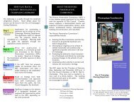
Draft Report<strong>West</strong> <strong>Washington</strong> <strong>Street</strong> Watershed Master PlanGOAL A:Identify stormwater run<strong>of</strong>f problemareas within the <strong>West</strong> <strong>Washington</strong><strong>Street</strong> <strong>watershed</strong>.Description:Based on input from the community, historical data, visual observation, and contributions fromthe <strong>City</strong> <strong>of</strong> <strong>Champaign</strong> the intersection <strong>of</strong> <strong>West</strong> <strong>Washington</strong> <strong>Street</strong> and North Russell <strong>Street</strong> hasbeen identified as one <strong>of</strong> the <strong>City</strong>’s key flooding problem areas. Visual inspection <strong>of</strong> the area,examination <strong>of</strong> contours, and analysis <strong>of</strong> the storm sewer network reveal that the <strong>West</strong><strong>Washington</strong> <strong>Street</strong> storm sewer is the primary drainage outlet for the area. As there no longerexists a primary overland flood route due to the <strong>watershed</strong> being completely developed, the <strong>City</strong>relies entirely on its sewer system to convey stormwater run<strong>of</strong>f. When the storm sewer system isfully surcharged, stormwater run<strong>of</strong>f ponds on the surface and finds an overland flow path alongthe <strong>Washington</strong> <strong>Street</strong> corridor through yards in residential areas towards the Copper Slough.For the purposes <strong>of</strong> this report, the <strong>West</strong> <strong>Washington</strong> <strong>Street</strong> corridor will be defined by the areaenclosed by the red box in Figure 2-3. The limits <strong>of</strong> this area were determined by the input fromthe <strong>City</strong> and local residents, as well as from the XP-SWMM computer model results. This areadoes not represent all the problem areas or even contains the entire extent <strong>of</strong> flooding at theintersection <strong>of</strong> <strong>West</strong> <strong>Washington</strong> <strong>Street</strong> and North Russell <strong>Street</strong>, but does show where the root <strong>of</strong>many <strong>of</strong> the <strong>watershed</strong> issues is located. Any proposed improvements located within the<strong>Washington</strong> <strong>Street</strong> corridor will have an impact on the entire <strong>watershed</strong> since this area containsthe <strong>West</strong> <strong>Washington</strong> <strong>Street</strong> trunk sewer through the residential areas and the junction <strong>of</strong> the <strong>West</strong><strong>Washington</strong> <strong>Street</strong> trunk sewer and the other trunk sewers in the sewer network.September 20092-5Clark Dietz, Inc.
Draft Report<strong>West</strong> <strong>Washington</strong> <strong>Street</strong> Watershed Master PlanFigure 2-3<strong>West</strong> <strong>Washington</strong> <strong>Street</strong> Corridor MapThe analysis <strong>of</strong> the <strong>West</strong> <strong>Washington</strong> <strong>Street</strong> corridor includes an examination <strong>of</strong> the otherproblem areas (within the <strong>West</strong> <strong>Washington</strong> <strong>Street</strong> <strong>watershed</strong>) to develop a more completeunderstanding <strong>of</strong> the areas prone to flooding and what is needed to improve the flooding situationin the <strong>West</strong> <strong>Washington</strong> <strong>Street</strong> <strong>watershed</strong>. The low area northeast <strong>of</strong> the intersection <strong>of</strong> NorthMattis Avenue and Glenn Park Drive is an area <strong>of</strong> concern when upstream stormwater run<strong>of</strong>fcauses surface flow along the <strong>West</strong> <strong>Washington</strong> <strong>Street</strong> corridor and local slopes divert flowtowards this low area. During precipitation events where surface flow north <strong>of</strong> <strong>West</strong> <strong>Washington</strong><strong>Street</strong> occurs, the natural tendency is for the stormwater run<strong>of</strong>f to follow the defined overlandflow path shown in Figure 2-4. This results in surface flow on and north <strong>of</strong> <strong>West</strong> <strong>Washington</strong><strong>Street</strong>, that ponds and flows through yards west towards North Draper Avenue and North GarfieldAvenue where the flow is detained in the low area.September 20092-6Clark Dietz, Inc.
Draft Report<strong>West</strong> <strong>Washington</strong> <strong>Street</strong> Watershed Master PlanGOAL B:Determine the cause <strong>of</strong> the floodingproblemsDescription:The flooding at the <strong>West</strong> <strong>Washington</strong> <strong>Street</strong> and North Russell <strong>Street</strong> intersection is not due to thenumber <strong>of</strong> curb inlets available, but from some other factor or combination <strong>of</strong> factors. The surveyinformation and other gathered data were used to develop an XP-SWMM model that couldsimulate the drainage pattern <strong>of</strong> the <strong>West</strong> <strong>Washington</strong> <strong>Street</strong> <strong>watershed</strong>. Hydraulic restrictions,flow conveyance patterns, ponding in intersections and other <strong>watershed</strong> characteristics weredetermined using the existing conditions XP-SWMM model. Calibration <strong>of</strong> the model could onlybe approximated by using the information provided by the <strong>City</strong> and the local Steering Committee,consisting <strong>of</strong> approximate observed flood depths and flow patterns at the intersection <strong>of</strong> <strong>West</strong><strong>Washington</strong> and North Russell as well as other documented flooding areas.The XP-SWMM Copper Slough model (developed by Clark Dietz Inc.) was used as the basemodel for the <strong>West</strong> <strong>Washington</strong> <strong>Street</strong> <strong>watershed</strong> model to develop the most accurate downstreamboundary conditions, as the <strong>West</strong> <strong>Washington</strong> <strong>Street</strong> storm sewer outlets directly to this system.Objectives:1. Develop a hydrologic/hydraulic model (XP-SWMM) that incorporates the sewer surveyinformation, along with the information from the <strong>City</strong> and contours from the County.2. Evaluate model results in the context <strong>of</strong> observed flooding conditions.3. Utilize the existing Copper Slough Watershed XP-SWMM model and integrate a detaileddrainage branch for the <strong>West</strong> <strong>Washington</strong> <strong>Street</strong> <strong>watershed</strong>.September 20092-8Clark Dietz, Inc.
Draft Report<strong>West</strong> <strong>Washington</strong> <strong>Street</strong> Watershed Master PlanGOAL C:Develop alternatives to improveconditions in problem areasDescription:The drainage area served by the <strong>West</strong> <strong>Washington</strong> <strong>Street</strong> storm sewer is entirely developed, witha few open areas near the industrial facilities and at parks. Incorporating flood control solutionsinto the existing <strong>watershed</strong> will require creative options and this Watershed Master Plan aims todevelop multiple options in an attempt to improve the drainage analysis and provide betterrecommendations. The existing conditions XP-SWMM model was modified to estimate howeach option would perform under expected hydrological conditions. Each multi-phase alternativescenario would be subjected to identical hydrological conditions and adjusted so that surfaceflooding for the 10-year, 2-hour storm would not occur at the intersection <strong>of</strong> <strong>West</strong> <strong>Washington</strong>and North Russell, as well as at the other identified areas throughout the <strong>watershed</strong>. Waterquality benefits <strong>of</strong> each alternative were studied on a conceptual level and benefits <strong>of</strong> eachalternative were included in the final analysis.Objectives:1. Modify the existing conditions XP-SWMM model to incorporate the various alternatives intoseparate model scenarios.2. Test the multi-phase improvement scenarios against the 10-year, 2-hour storm to demonstrateno ponding at the intersection <strong>of</strong> <strong>West</strong> <strong>Washington</strong> and North Russell and no surfacesurcharge along the main trunk sewers. Analyze each scenario against the 50-year, 2-hourstorm event to verify the extent <strong>of</strong> flooding and flood routing for large storm events.3. Address the economic and construction feasibility <strong>of</strong> each alternative in the final analysis,with consideration towards phasing and implementation strategy.September 20092-9Clark Dietz, Inc.
Draft Report<strong>West</strong> <strong>Washington</strong> <strong>Street</strong> Watershed Master PlanGOAL D:Discuss problem areas within the<strong>West</strong> <strong>Washington</strong> <strong>Street</strong> <strong>watershed</strong>related to stormwater run<strong>of</strong>f qualityand possible solutions.Description:Sanitary sewer concerns caused by the surcharged conditions in the storm sewers will only bediscussed in this report and will not involve an in depth analysis and modeling <strong>of</strong> the system;however, the sanitary sewer system is a separate sewer system in this <strong>watershed</strong> and is connectedto the stormwater run<strong>of</strong>f when ponding occurs and therefore should be part <strong>of</strong> a separate study.The ponding along the storm sewers in the <strong>West</strong> <strong>Washington</strong> <strong>Street</strong> <strong>watershed</strong> likely increase wetweather flows to the sanitary sewers through surface and groundwater inflows and infiltration.The assumption made during the preliminary analysis was that stormwater run<strong>of</strong>f would impactthe storm sewer system and only surface ponding would have limited access to the sanitarysewers.The <strong>West</strong> <strong>Washington</strong> <strong>Street</strong> <strong>watershed</strong> is predominately medium density residential land use,with only a portion <strong>of</strong> the area dedicated to commercial or industrial use. Any contaminants inthe Copper Slough cannot be directly linked to this drainage area; however, improvements to thewater quality <strong>of</strong> the run<strong>of</strong>f from the <strong>West</strong> <strong>Washington</strong> <strong>Street</strong> <strong>watershed</strong> could potentially improveconditions in the Copper Slough. Recommendations for flooding improvements should considerpotential stormwater BMPs in conjunction with traditional stormwater management (i.e. floodcontrol) techniques.Objectives:1. Discuss stormwater improvements that provide stormwater quality benefits.September 20092-10Clark Dietz, Inc.
Draft Report<strong>West</strong> <strong>Washington</strong> <strong>Street</strong> Watershed Master PlanUnder this modeling approach the <strong>West</strong> <strong>Washington</strong> <strong>Street</strong> trunk storm sewer will experiencedifferent tailwater conditions for different recurrence interval storm events.3.4 FIELD SURVEYClark Dietz performed a field survey <strong>of</strong> the <strong>West</strong> <strong>Washington</strong> <strong>Street</strong> trunk storm sewer, the <strong>West</strong><strong>Washington</strong> <strong>Street</strong> corridor, and key ground and sewer junction elevations throughout the<strong>watershed</strong>. The survey was necessary to build an accurate hydraulic model <strong>of</strong> the storm sewernetwork and potential surface flow paths.GPS survey equipment was used to collect the majority <strong>of</strong> survey points. Where satellitecoverage was unavailable, traditional (i.e. Total Station) survey methods were used to supplementthe survey data as necessary. Survey elevations were checked against contour elevations to lookfor inconsistencies and accuracy issues before these values were used in the computer model.Clark Dietz surveyed the manhole locations using GPS-based survey and followed up withmanhole inspections. These inspections included depth measurements to storm sewer invertelevations and confirmation <strong>of</strong> pipe sizes and pipe connectivity. Critical ground and pavementelevations were surveyed to determine the important surface overflow points and flow pathswithin the drainage areas. Contour information was used to estimate ground elevations for areasbetween survey points.3.5 PUBLIC INPUTThe <strong>City</strong> <strong>of</strong> <strong>Champaign</strong> and Clark Dietz have gathered public input through site visits withresidents, public meetings and resident surveys. This public input was used in the problemdetermination, as well as the alternatives development in an effort to better understand thedrainage problems within the <strong>watershed</strong> and tailor alternatives to address these issues. Sets <strong>of</strong>meeting minutes can be found in Appendix A. These meeting minutes include notes from theinitial problem determination meeting and the meeting with eth Fountain Head Drainage District.Additional public meetings occurred to present and discuss the presented alternatives to obtainpublic input on the potential detention pond locations and the combinations scenarios.September 20093-2Clark Dietz, Inc.
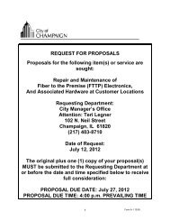
Draft Report<strong>West</strong> <strong>Washington</strong> <strong>Street</strong> Watershed Master Plan4.0 PRELIMINARY PROBLEM IDENTIFICATION4.1 STORMWATER PROBLEM IDENTIFICATION PROCESSStormwater problem areas were identified through discussions with <strong>City</strong> staff and local residentsand were based on observations and documentation. After the initial problem identificationeffort, XP-SWMM modeling was performed to verify these problem areas and identifypreviously-undocumented problems (see Chapter 5 for existing conditions modeling). Keylocations were then selected for detailed hydrologic/hydraulic analysis and solution development(Chapter 6). The following text summarizes the initial problem identification process.4.2 EXISTING STORM SEWERThe primary reason for this drainage study is to solve the chronic flooding that occurs at the <strong>West</strong><strong>Washington</strong> and North Russell intersection and surrounding areas during significant wet weatherevents. The damage and inconvenience this creates exceeds an acceptable level and the <strong>City</strong> hasdetermined that this problem area needs to be addressed. The existing storm sewer systemconsists <strong>of</strong> two main trunk storm sewers feeding into the <strong>West</strong> <strong>Washington</strong> <strong>Street</strong> trunk sewer,just north <strong>of</strong> the <strong>West</strong> <strong>Washington</strong> <strong>Street</strong> and North Russell <strong>Street</strong> intersection, as shown inFigure 4-1.Figure 4-1<strong>West</strong> <strong>Washington</strong> <strong>Street</strong> Watershed Trunk Storm SewersSeptember 20094-1Clark Dietz, Inc.
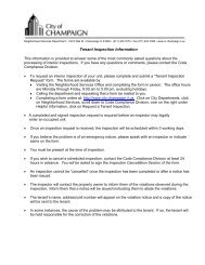
Draft Report<strong>West</strong> <strong>Washington</strong> <strong>Street</strong> Watershed Master PlanAfter initial inspection <strong>of</strong> the <strong>West</strong> <strong>Washington</strong> <strong>Street</strong> and North Russell <strong>Street</strong> problem area, itbecame apparent that the flooding is not caused by a lack <strong>of</strong> curb inlets. Basic problems in thisarea originate from the local topography <strong>of</strong> the neighborhood and the storm sewer networkstructure. The <strong>West</strong> <strong>Washington</strong> and North Russell intersection is the location <strong>of</strong> the primaryhydraulic restriction in the storm sewer. A 36-inch storm sewer from the north combines with a27-inch storm sewer from the south and discharges into a 36-inch storm sewer flowing west.This configuration severally restricts flow and results in surcharging <strong>of</strong> the system until surfaceponding and conveyance occurs. Figure 4-2 shows the storm sewer network layout that is themain cause <strong>of</strong> the hydraulic restriction in the <strong>watershed</strong>.36”36”27”Figure 4-2Storm Sewer Network at the Intersection <strong>of</strong><strong>West</strong> <strong>Washington</strong> <strong>Street</strong> and North Russell <strong>Street</strong>The XP-SWMM model was developed with the goal <strong>of</strong> discovering any less obvious causes <strong>of</strong>flooding within the <strong>West</strong> <strong>Washington</strong> and North Russell intersection. Other than a lack <strong>of</strong> inletsor undersized sewer pipe, the potential <strong>of</strong> backflow from the surcharged storm sewer needed to beruled out as a potential cause <strong>of</strong> surface flooding. The XP-SWMM model accounts forSeptember 20094-2Clark Dietz, Inc.
Draft Report<strong>West</strong> <strong>Washington</strong> <strong>Street</strong> Watershed Master Plansimultaneous subsurface (sewer) and overland (flood) routing, which allows for a realisticsimulation <strong>of</strong> actual flooding dynamics.4.3 KNOWN FLOODING ISSUES<strong>City</strong> staff and local residents have observed surface flooding at the intersection <strong>of</strong> <strong>West</strong><strong>Washington</strong> <strong>Street</strong> and North Russell <strong>Street</strong>, which includes standing water in the intersections aswell as yard drainage during larger storm events. The frequency and severity <strong>of</strong> flooding at anintersection is <strong>of</strong>ten associated with a lack <strong>of</strong> sewer inlets and/or inadequate sewer capacity.These issues can be caused by debris buildup, deterioration <strong>of</strong> the sewers or under-sized pipes andstructures. Flooding at this intersection is impacting dozens <strong>of</strong> homes when ponding at the <strong>West</strong><strong>Washington</strong> and North Russell floods the intersection and flows west along <strong>West</strong> <strong>Washington</strong><strong>Street</strong> and between homes north <strong>of</strong> <strong>West</strong> <strong>Washington</strong> <strong>Street</strong> (see Figure 4-3). Precipitation eventsthat exceed the 2-year, 24-hour storm peak flow triggers ponding and surface conveyance that cancause damage to structures and landscaping. Surface flooding occurs frequent enough to warrantfurther attention to determine the cause <strong>of</strong> this stormwater drainage concern.Figure 4-3Surface Flooding Impact AreaSeptember 20094-3Clark Dietz, Inc.
Draft Report<strong>West</strong> <strong>Washington</strong> <strong>Street</strong> Watershed Master PlanJust north <strong>of</strong> the intersection <strong>of</strong> North Mattis Avenue and Glenn Park Drive is another area that isa natural low spot that gathers stormwater surface run<strong>of</strong>f resulting in nuisance flooding shown inFigure 4-4 as the red area. Flooding in this area originates from the surface flow along the <strong>West</strong><strong>Washington</strong> <strong>Street</strong> corridor and the <strong>West</strong> <strong>Washington</strong> <strong>Street</strong> storm sewer surcharging. Surfacestormwater flow along the <strong>West</strong> <strong>Washington</strong> <strong>Street</strong> corridor, eventually flows to the low pointjust east <strong>of</strong> North Mattis Avenue. Surface inlets and ground slopes direct a portion <strong>of</strong> this flowback to the <strong>West</strong> <strong>Washington</strong> <strong>Street</strong> trunk storm sewer, while the remainder <strong>of</strong> the standing run<strong>of</strong>fis infiltrated. This configuration produces standing water that may take an extended period <strong>of</strong>time to recede, acting as an un<strong>of</strong>ficial detention basin for the <strong>West</strong> <strong>Washington</strong> <strong>Street</strong> <strong>watershed</strong>.The current storm sewer system and ground slopes prohibit adequate drainage <strong>of</strong> this area.Figure 4-4Surface Flooding at North Mattis Avenue and Glenn Park DriveThe 1200 Block <strong>of</strong> <strong>West</strong> University Avenue, North James <strong>Street</strong>, <strong>West</strong> Columbia Avenue, NorthDraper Avenue and many other problem areas shown in Figure 2-2 occur along or upstream <strong>of</strong>the <strong>West</strong> <strong>Washington</strong> <strong>Street</strong> trunk sewer. Other issues that exist in the <strong>West</strong> <strong>Washington</strong> <strong>Street</strong>September 20094-4Clark Dietz, Inc.
Draft Report<strong>West</strong> <strong>Washington</strong> <strong>Street</strong> Watershed Master Plan<strong>watershed</strong> include basement flooding, illicit storm sewer connections, and other localize floodingareas. Basement flooding could be attributed to any number <strong>of</strong> factors, including surcharge fromboth storm and sanitary sewers, footing tile failures, sump pump deficiencies, wall leakage andservice line failures. Downspout connections and other home connections to the storm sewershould be disconnected so that these connections do not consume available conveyance capacity<strong>of</strong> the storm sewer. Disconnection <strong>of</strong> footing/downspout connections, in combination with a sumppump installation/retr<strong>of</strong>it program, should <strong>of</strong>fer some flooding protection for homes not locatedwithin the problem areas. Localized flooding will be addressed on a more conceptual level unlesshydraulic restrictions or <strong>City</strong> concerns warrant additional analysis.4.4 ALTERNATIVES ANALYSISThe alternatives modeling effort helped to determine how each alternative would impact thestorm sewer system along the <strong>West</strong> <strong>Washington</strong> <strong>Street</strong> corridor and throughout the <strong>watershed</strong>.Each alternative concept was integrated into the existing conditions XP-SWMM model to testboth the benefits, as well as the feasibility <strong>of</strong> each option. The alternatives models were analyzedfor potential problem areas so that the proposed alternatives would not create new issues thatwould adversely affect other areas <strong>of</strong> the <strong>watershed</strong>. Each model was tested to ensure that the 50-year, 2-hour storm could be conveyed through the system. The 10-year, 2-hour storm is the targetdesign storm event that was used to minimize the potential for surface flooding near theintersection <strong>of</strong> <strong>West</strong> <strong>Washington</strong> <strong>Street</strong> and North Russell <strong>Street</strong>.4.5 WATER QUALITYWater quality is a key issue with respect to <strong>watershed</strong> planning. The following drivers obligatethe <strong>City</strong> to address water quality when implementing <strong>watershed</strong> improvements:• NPDES MS4 Permit: The <strong>City</strong> has held an NPDES permit for their stormwater systemsince 2003. This permit obligation will continue into the foreseeable future. Thispermit requires the <strong>City</strong> to take specific steps to reduce the potential for pollution inreceiving waters by implementing stormwater BMPs in existing and developing areas.• Local stakeholder interest: Residents, local environmental advocacy groups, University<strong>of</strong> Illinois academic community, and the Urbana-<strong>Champaign</strong> Sanitary District (UCSD)all have unique needs that are aligned with wet weather issues in the <strong>West</strong> <strong>Washington</strong><strong>Street</strong> and Copper Slough <strong>watershed</strong>s.• Potential for TMDLs along the Copper Slough: Although there are currently nonumerical water quality standards for the <strong>watershed</strong>s immediately impacted by activitiesin the Copper Slough <strong>watershed</strong>, the state may enact those standards in the future. Suchstandards, known as TMDLs (Total Maximum Daily Loads), could require morestringent water quality monitoring and infrastructure retr<strong>of</strong>it.• Environmental Sustainability: Stormwater management has a direct impact on the localenvironment, including channel stability, water quality, and flood control. Localconcerns about these issues require the exploration <strong>of</strong> land use practices that encourageemerging stormwater management practices. Known as Low Impact Development(LID), this type <strong>of</strong> design takes a different approach to stormwater management.Instead <strong>of</strong> moving stormwater directly to the storm sewer system, special stormwaterfeatures are constructed that encourage stormwater to be held back and infiltrated intothe underlying soils, thus reducing run<strong>of</strong>f volume and providing a natural filter toSeptember 20094-5Clark Dietz, Inc.
Draft Report<strong>West</strong> <strong>Washington</strong> <strong>Street</strong> Watershed Master Planreduce stormwater pollution. Implementing this type <strong>of</strong> design in the <strong>West</strong> <strong>Washington</strong><strong>Street</strong> <strong>watershed</strong> would be consistent with recommendations in the Copper SloughWatershed Master Plan prepared for the <strong>City</strong> <strong>of</strong> <strong>Champaign</strong>, and would also help the<strong>City</strong> demonstrate its continued compliance with its NPDES municipal stormwaterpermit.4.6 STATUS OF THE COPPER SLOUGHWater pollution control programs are designed to protect the “designated uses” <strong>of</strong> the waterresources <strong>of</strong> the state. Each state has the responsibility to set water quality standards that protectthese designated uses, which include aquatic life, wildlife, agricultural use, primary contact (e.g.swimming, water skiing), secondary contact (e.g. boating, fishing), industrial use, drinking water,food-processing water supply, and aesthetic quality.Section 303(d) <strong>of</strong> the federal Clean Water Act (CWA) requires states to identify waters that donot meet applicable water quality standards or do not fully support their designated uses. Statesare required to submit a prioritized list <strong>of</strong> impaired waters, known as the 303(d) List, to theUSEPA for review and approval.The CWA also requires that a Total Maximum Daily Load (TMDL) be developed for eachpollutant <strong>of</strong> an impaired waterbody. The establishment <strong>of</strong> a TMDL sets the pollutant reductiongoal necessary to improve impaired waters.The Copper Slough is currently not listed as a 303(d) impaired stream. There is no evidence toidentify the <strong>West</strong> <strong>Washington</strong> <strong>Street</strong> <strong>watershed</strong> as a possible source <strong>of</strong> stormwater contaminants;however, stormwater run<strong>of</strong>f in the <strong>West</strong> <strong>Washington</strong> <strong>Street</strong> <strong>watershed</strong> will contribute urbanrun<strong>of</strong>f to the Copper Slough, which typically carries known pollutants, such as nutrients (nitrogenand phosphorus), heavy metals (lead and copper) and bacteria (fecal coliform) from animal waste.The Copper Slough does not currently have TMDLs established for the downstream reach andthere is no timetable for TMDL development for this <strong>watershed</strong>. However, the IllinoisEnvironmental Protection Agency (IEPA) may choose to add the Copper Slough to their TMDLWatershed List in the future. At this time, there is no indication when (and if) that will occur.As part <strong>of</strong> the <strong>City</strong>’s NPDES municipal stormwater permit (ILR40), the <strong>City</strong> is expected toaddress stormwater quality to receiving streams. Where possible, BMPs should be implementedin new and existing developed areas to reduce the pollution potential from urban run<strong>of</strong>f. As theCopper Slough is not listed as an impaired stream, the <strong>West</strong> <strong>Washington</strong> <strong>Street</strong> <strong>watershed</strong> wouldbe an ideal location in which to practice measures aimed at reducing pollution throughstormwater BMPs as a proactive measure.4.7 <strong>West</strong> <strong>Washington</strong> <strong>Street</strong> Watershed BaseflowThere is significant baseflow within the <strong>West</strong> <strong>Washington</strong> <strong>Street</strong> trunk storm sewer during dryweather, sometimes flowing a third full a week after a precipitation event. There are no identifiedsources <strong>of</strong> this baseflow, although possible water main leaks, groundwater infiltration and othersources are all being considered by the <strong>City</strong>. Sewer televising has not produced any clear sources<strong>of</strong> storm sewer inflows, although the <strong>City</strong> will continue to investigate the sewers in this <strong>watershed</strong>in order to reduce the baseflow in the <strong>West</strong> <strong>Washington</strong> <strong>Street</strong> trunk sewer.September 20094-6Clark Dietz, Inc.
Draft Report<strong>West</strong> <strong>Washington</strong> <strong>Street</strong> Watershed Master Plan5.0 EXISTING CONDITIONS HYDROLOGIC/HYDRAULIC ANALYSIS:KEY FINDINGS5.1 INTRODUCTION TO MODELING TECHNIQUES5.1.1 IntroductionThe hydrologic/hydraulic modeling program XP-SWMM 2009, version 11.1, was used toestimate peak flow rates and determine the hydraulic capacity <strong>of</strong> the <strong>West</strong> <strong>Washington</strong><strong>Street</strong> trunk sewer. XP-SWMM is a physically-based storm event simulation modelcapable <strong>of</strong> simulating run<strong>of</strong>f from various land uses and soil types, combining sub-basinhydrographs, and routing flow through storage (detention ponds, natural low areas) andconveyance elements (channel or sewers).XP-SWMM integrates the hydrologic analysis with the hydraulic analysis, so anystormwater storage resulting from detention ponds or surface flooding is calculated andpeak flows are adjusted accordingly. Flow data used for the hydraulic analysis consisted<strong>of</strong> unsteady flow data computed using the hydrologic analysis tool <strong>of</strong> XP-SWMM. Peakflows from the hydrologic analysis were used to compute a hydraulic grade line (HGL)for each section <strong>of</strong> sewer pipe and open drainage channel.An Existing Conditions XP-SWMM model was developed to simulate the <strong>watershed</strong>under existing land use conditions. The key findings <strong>of</strong> the Existing Conditions XP-SWMM model are discussed in this chapter. Chapter 6 includes discussion <strong>of</strong> ProposedConditions modeling.5.1.2 Hydraulics – Trunk Sewer ParametersTrunk storm sewers were identified from the <strong>City</strong>’s storm sewer map and confirmed bysurvey data. Sewer survey data collected included manhole rim elevations, pipe sizes,pipe connectivity, and invert elevations, so that accurate information could be used whenthe XP-SWMM existing conditions model was developed. The drainage areas weredelineated based on the sewer network and contours so that portions <strong>of</strong> the network couldbe assigned local drainage areas that would be conveyed to the trunk sewer. Thecomputer model has each drainage area assigned to the appropriate node along the <strong>West</strong><strong>Washington</strong> <strong>Street</strong> trunk sewers to simulate the flow conditions within the <strong>watershed</strong>.The roadways and surfaces along the <strong>West</strong> <strong>Washington</strong> <strong>Street</strong> corridor were also modeledas a link or node to provide conveyance and storage potential based on the existingtopography. The roadway cross sections were approximated as shallow channel crosssections based on the survey information and the 2-foot contours (2008). This was donein order to more accurately model the larger precipitation events, allowing the flow,which surcharges the <strong>West</strong> <strong>Washington</strong> <strong>Street</strong> trunk sewer, to flow downstream via theroadway or surface channel.5.1.3 Hydrology – Subbasin ParametersThe 408-acre <strong>watershed</strong> was subdivided into 30 individual subbasins to quantify thestormwater run<strong>of</strong>f contribution from individual portions <strong>of</strong> the <strong>watershed</strong> (see Figure 5-1). Subbasin delineation was performed using 2-foot contours (2008) provided by theSeptember 20095-1Clark Dietz, Inc.
Draft Report<strong>West</strong> <strong>Washington</strong> <strong>Street</strong> Watershed Master Plan<strong>Champaign</strong> County GIS Consortium and by determining the locations <strong>of</strong> storm sewersusing field survey and the <strong>City</strong> storm sewer map. Storm sewers that cross the <strong>watershed</strong>boundaries and appear to be sloped away from the <strong>West</strong> <strong>Washington</strong> <strong>Street</strong> <strong>watershed</strong>were not evaluated or modeled as part <strong>of</strong> this study, but were assumed to be appropriatelysized and sloped to adequately convey stormwater run<strong>of</strong>f away from the <strong>West</strong><strong>Washington</strong> <strong>Street</strong> <strong>watershed</strong>. A few areas along the sewershed boundary had groundslopes toward the <strong>West</strong> <strong>Washington</strong> <strong>Street</strong> <strong>watershed</strong>, but sewers tributary to anotherstorm sewer. In these instances, the drainage area was added to the <strong>West</strong> <strong>Washington</strong><strong>Street</strong> <strong>watershed</strong> to more accurately model peak flows associated with large storm eventsthat would exceed sewer capacity.Figure 5-1<strong>West</strong> <strong>Washington</strong> <strong>Street</strong> Watershed Subbasin MapSoil types, provided in shapefile format by the <strong>City</strong> <strong>of</strong> <strong>Champaign</strong>, were used to assignrun<strong>of</strong>f variables for the surface conditions <strong>of</strong> each local drainage area. The Green Amptmethod was used to determine flood routing and infiltration conditions throughout thesewershed. The soil types within the <strong>watershed</strong> are a combination <strong>of</strong> silt loam, silty clay,and loam, which were used in determining the Green Ampt flood routing and infiltrationparameters. Based on these soil types, the average capillary suction was between 8 and12 inches, the initial moisture deficit was between 0.25 and 0.32, and the saturatedhydraulic conductivity was between 0.2 and 0.6 in/hr.September 20095-2Clark Dietz, Inc.
Draft Report<strong>West</strong> <strong>Washington</strong> <strong>Street</strong> Watershed Master PlanThe depression storage variables were determined using the default methods within thes<strong>of</strong>tware. The impervious area variables were calculated using the equationDp=0.0303*S^(-0.49), where the average catchment slope (S), in percent, was assumedto be 2% throughout the <strong>watershed</strong> for an impervious depression storage <strong>of</strong> 0.021. Thepervious depression storage for grassed urban surfaces is typically 0.1 inches. TheManning’s “n” values were determined using values from the imbedded tables within thes<strong>of</strong>tware, resulting in an impervious Manning’s “n” value <strong>of</strong> 0.014 and a pervious value<strong>of</strong> 0.3. The zero detention (%), the portion <strong>of</strong> the <strong>watershed</strong> that drains directly to thestorm sewers, was lowered from the default <strong>of</strong> 25% to a more typical value <strong>of</strong> 20%.The Copper Slough XP-SWMM model used the SCS method for infiltration calculations.The curve numbers were between 73 and 95, with corresponding times <strong>of</strong> concentration.This method is useful for large <strong>watershed</strong>s or when soil data is unavailable, but the <strong>West</strong><strong>Washington</strong> <strong>Street</strong> <strong>watershed</strong> has soil type data readily available and therefore makes theGreen Ampt method a more accurate run<strong>of</strong>f determination method. The ranges <strong>of</strong>variables used in the Green Ampt method are typical <strong>of</strong> type B soils for the SCS method,which are used in the Copper Slough XP-SWMM model.5.2 DESIGN STORMS AND PEAK FLOW ESTIMATIONSynthetic (design) storms were used to predict peak flows throughout the <strong>watershed</strong> underexisting conditions and to model proposed improvements. The <strong>West</strong> <strong>Washington</strong> <strong>Street</strong> peakflow rates were evaluated using the 2-hour storm with the following return intervals: 50-year, 25-year, 10-year, 5-year, and 1-year. The 2-hour duration was the critical duration storm, having themost impact on high water levels throughout the system, and was used in the flooding analysis.The trunk storm sewers were evaluated using the 10-year storm, consistent with the <strong>City</strong>’s currentdesign criteria (many <strong>of</strong> the existing trunk sewers were built prior to the 10-year design standard).Time distributions for rainfall (Huff curves) were used as published in “Bulletin 71 - RainfallFrequency Atlas <strong>of</strong> the Midwest” (Midwestern Climate Center and Illinois State Water Survey,1992). The Huff 1 st Quartile distribution was used for the storms. Rainfall depths are shown foreach design storm in Table 5-1.Table 5-1Rainfall depths (in) for typical storms at Urbana, IllinoisSource: Bulletin 70Storm FrequencyStormDuration 50 year 25 year 10 year 5 year 1 year2 hour 3.22 2.86 2.48 2.18 1.522-hour 3.44 2.97 2.52 2.19 1.46The top row in Table 5-1 represents the precipitation data for the <strong>City</strong> <strong>of</strong> Urbana in the pointrainfall tables <strong>of</strong> Bulletin 70 and the bottom row displays the rainfall data for the Eastern region<strong>of</strong> Illinois in the area tables <strong>of</strong> Bulletin 70. The area tables may produce a more conservativerainfall depth for modeling; however, the area tables provide an average rainfall depth for aSeptember 20095-3Clark Dietz, Inc.
Draft Report<strong>West</strong> <strong>Washington</strong> <strong>Street</strong> Watershed Master Planseveral county area and are normally used for large <strong>watershed</strong>s. The point rainfall tables aretraditionally used for smaller <strong>watershed</strong>s that are located near one <strong>of</strong> the cities listed in the table.The rainfall data at Urbana in the point rainfall tables better represents the local simulated rainfalldepths for this <strong>watershed</strong>. Since the difference in rainfall depths is minor and the point rainfalltable data is traditionally used for small <strong>watershed</strong>s, the point rainfall table data (row 1 in Table5-1) will be used in this study.5.2.1 Downstream Water ElevationsThe existing conditions downstream water elevation is modeled as a free outlet, whichmeans that there is no flooding or flow restrictions at the downstream point in the model.This condition typically does not exist for larger storm events and <strong>of</strong>ten requires anincrease in tailwater conditions to coincide with flooding along the channel. Thedownstream outlet conditions are located a few miles downstream <strong>of</strong> the <strong>West</strong><strong>Washington</strong> <strong>Street</strong> trunk storm sewer outlet and therefore have very little impact on thehydraulic conditions in the channel at this point. The water elevation near the seweroutlet likely represents an accurate water level in the Copper Slough for the design stormbeing simulated. There are no required changes to variables between model runs otherthan the storm type to set the tailwater conditions in the Copper Slough at the <strong>West</strong><strong>Washington</strong> <strong>Street</strong> storm sewer outlet.5.3 EXISTING CONDITIONS: KEY FINDINGSThe Existing Conditions XP-SWMM model was used to identify where undersized sewers mayexist. The 10-year recurrence interval storm (2-hour duration) was used to evaluate existingstorm sewers for surface flooding potential. The 50-year storm was used to evaluate the impacts(locations and depth) <strong>of</strong> surface flooding routing.The 2-hour duration storm was chosen as it represents the critical duration for a <strong>watershed</strong> <strong>of</strong> thissize. For smaller urbanized <strong>watershed</strong>s (less than one square mile), the 2-hour duration rainfalltypically generates the highest peak flow calculations.5.3.1 Undersized Trunk Storm SewersTrunk storm sewers are defined as undersized where the Existing Conditions XP-SWMMmodel predicted one or both <strong>of</strong> the following scenarios (under 10-year storm conditions):• The slope <strong>of</strong> the hydraulic grade line exceeds the slope <strong>of</strong> the sewer• The hydraulic grade line exceeds the ground surface, indicating floodingpotentialFigure 5-2 illustrates the locations <strong>of</strong> all trunk sewers modeled as part <strong>of</strong> this study.Undersized trunk storm sewers are identified below. The following text describes theindividual problems associated with the undersized trunk sewer:<strong>West</strong> <strong>Washington</strong> <strong>Street</strong>: Between North Russell <strong>Street</strong> and the Copper Slough, the 36and 42-inch diameter trunk storm sewer north <strong>of</strong> <strong>West</strong> <strong>Washington</strong> <strong>Street</strong> (see Figure 5-2) is undersized. The majority <strong>of</strong> flow (for the 10-year storm) is conveyed west viaun<strong>of</strong>ficial surface flow or stored in localized depressions along the <strong>West</strong> <strong>Washington</strong><strong>Street</strong> corridor.September 20095-4Clark Dietz, Inc.
Draft Report<strong>West</strong> <strong>Washington</strong> <strong>Street</strong> Watershed Master PlanPipe Junction LocationFigure 5-2<strong>West</strong> <strong>Washington</strong> <strong>Street</strong> Watershed Trunk Storm SewersTable 5-2<strong>West</strong> <strong>Washington</strong> <strong>Street</strong> Trunk SewerDiameter(in)Inflow SewersArea(in 2 )PipeCapacity(cfs)*Diameter(in)Outflow SewersArea(in 2 )PipeCapacity(cfs)*<strong>West</strong> <strong>Washington</strong> <strong>Street</strong> and 27 andNorth Russell <strong>Street</strong>361590.4 29.9 36 1017.8 31.3North <strong>of</strong> <strong>West</strong> <strong>Washington</strong> <strong>Street</strong> 8, 12,and North Garfield Avenue and 361181.2 42.0 36 1017.8 34.2North <strong>of</strong> <strong>West</strong> <strong>Washington</strong> <strong>Street</strong> 18 andand Carson Avenue361209.5 44.2 36 1017.8 36.7North <strong>of</strong> <strong>West</strong> <strong>Washington</strong> <strong>Street</strong> 18 andand Miller Avenue361272.3 41.3 36 1017.8 41.7North <strong>of</strong> <strong>West</strong> <strong>Washington</strong> <strong>Street</strong> 24 andand North Victor <strong>Street</strong>361470.2 47.7 36 1017.8 51.6* Assumes minimum slope for smaller diameter sewers and pipe flowing under gravitySeptember 20095-5Clark Dietz, Inc.
Draft Report<strong>West</strong> <strong>Washington</strong> <strong>Street</strong> Watershed Master PlanThe storm sewer junctions displayed in Table 5-2 show the major intersections along the<strong>West</strong> <strong>Washington</strong> <strong>Street</strong> trunk storm sewer that contain either multiple inflows or largediameter sewers discharging into a manhole along the trunk sewer. The sewer sizes weredetermined by <strong>City</strong> shapefiles and survey information and were used for sewer area andflow calculations. The pipe capacity columns were determined by calculating themaximum flow possible under gravity flow. The pipe slopes were based on surveyinformation or assumed to be at minimum slope.The inflow sewers at all five junctions shown have an inflow area that is over 15% largerthan the outflow area. This is critical when the sewers are surcharged and subject topressurized flow. The pipe area will control the pressurized flow and with someintersections having inflow pipe areas over 50% greater than outflow sewers, thehydraulic restrictions along the trunk sewer are noticeable. When gravity flow existsduring smaller storm events, the flow capacity dictates the hydraulic restriction in thesewer system. The inflow sewer capacity is usually at or greater than the outlet sewer ateach junction except for the values highlighted in red. These inflow pipe capacities areactually lower than the outflow pipe capacities; however, the inflow sewers are belowminimum slope, which reduces the gravity flow in the sewer. The 27-inch sewer onNorth Russell <strong>Street</strong> (part <strong>of</strong> the North Edwin <strong>Street</strong> Trunk Sewer) was found to be at anegative slope, meaning that ponding at the structure in the <strong>West</strong> <strong>Washington</strong> and NorthRussell intersection has to occur before flow is discharged to the <strong>West</strong> <strong>Washington</strong> <strong>Street</strong>Trunk Sewer. The <strong>West</strong> <strong>Washington</strong> <strong>Street</strong> and North Victor <strong>Street</strong> junction has an outletsewer with a greater slope and higher capacity; however, the sewer system is typicallysurcharged in this area and rarely flows under gravity conditions for an entire stormevent.North McKinley Avenue: The trunk sewer serving the North McKinley Avenue drainagearea conveys flow from the northeastern portion <strong>of</strong> the <strong>West</strong> <strong>Washington</strong> <strong>Street</strong><strong>watershed</strong>. The 36-inch trunk storm sewer discharges to the <strong>West</strong> <strong>Washington</strong> <strong>Street</strong>trunk sewer just north <strong>of</strong> the intersection <strong>of</strong> <strong>West</strong> <strong>Washington</strong> <strong>Street</strong> and North Russell<strong>Street</strong>, draining approximately 118 acres. The following junctions occur along thissegment <strong>of</strong> storm sewer:Pipe Junction Location<strong>West</strong> Bradley Avenueand North McKinleyAvenue<strong>West</strong> Eureka <strong>Street</strong> andNorth McKinley Avenue<strong>West</strong> Tremont <strong>Street</strong> andNorth McKinley Avenue<strong>West</strong> Columbia Avenueand North Edwin <strong>Street</strong>Table 5-3North McKinley Avenue Trunk SewerDiameter(in)12 and15Inflow SewersArea(in 2 )PipeCapacity(cfs)*Diameter(in)Outflow SewersArea(in 2 )PipeCapacity(cfs)289.8 4.1 15 176.7 2.612, 18,and 18622.0 9.1 24 452.4 9.412 and24565.47 10.9 24 452.4 9.424 and361470.2 34.1 36 1017.8 25.1* Assumes minimum slope for smaller diameter sewers and pipe flowing under gravitySeptember 20095-6Clark Dietz, Inc.
Draft Report<strong>West</strong> <strong>Washington</strong> <strong>Street</strong> Watershed Master PlanThe North McKinley Avenue trunk sewer shows larger inflow sewer diameters and pipecapacity than outflow sewers for the junctions provided. The hydraulic conditions ateach <strong>of</strong> these junctions would produce hydraulic restrictions that are responsible for thelocalized flooding along North Willis Avenue and Alagna Drive that is predicted in themodel. The sewer junction at <strong>West</strong> Columbia Avenue and North Edwin <strong>Street</strong> is theworst junction hydraulically, leading to increased surface flooding in the <strong>West</strong><strong>Washington</strong> <strong>Street</strong> and North Russell <strong>Street</strong> neighborhood. The North McKinley Avenuetrunk sewer splits into a 36 and 24-inch sewer near the railroad tracks, but comes backtogether at the <strong>West</strong> Columbia Avenue and North Edwin <strong>Street</strong> intersection. This designsimply moves the flooding problem downstream, rather than providing additionalconveyance capacity.North Edwin <strong>Street</strong>: The 27-inch trunk storm sewer from the south serves about 153acres, primarily east <strong>of</strong> North Edwin <strong>Street</strong>. This trunk sewer has a smaller diameter thanthe North McKinley trunk storm sewer, yet drains a larger area. Hydraulic restrictionsexist along this trunk sewer, especially along the trunk sewer from the sewer junction justeast <strong>of</strong> the <strong>West</strong> University Avenue and North Russell <strong>Street</strong> intersection to the NorthEdwin <strong>Street</strong> and <strong>West</strong> <strong>Washington</strong> <strong>Street</strong> intersection. The following junctions occuralong this segment <strong>of</strong> storm sewer:Pipe Junction LocationEast <strong>of</strong> <strong>West</strong> University<strong>Street</strong> and North Russell<strong>Street</strong>East <strong>of</strong> <strong>West</strong> Park Avenueand North Russell <strong>Street</strong><strong>West</strong> Church <strong>Street</strong> andNorth Edwin <strong>Street</strong><strong>West</strong> <strong>Washington</strong> <strong>Street</strong>and North Edwin <strong>Street</strong>Table 5-4North Edwin <strong>Street</strong> Trunk SewerDiameter(in)8, 8, 15,18, and188, 18,and 2410, 18,and 2412, 18,and 24Inflow SewersArea(in 2 )PipeCapacity(cfs)*Diameter(in)Outflow SewersArea(in 2 )PipeCapacity(cfs)786.2 11.7 24 452.4 14.1757.1 22.1 24 452.4 16.1785.4 26.8 24 452.4 13.9819.9 24.5 24 452.4 15.5* Assumes minimum slope for smaller diameter sewers and pipe flowing under gravityThe sewer junction located east <strong>of</strong> <strong>West</strong> University <strong>Street</strong> and North Russell <strong>Street</strong> isroutinely flooded and therefore rarely acts under gravity flow conditions. The otherjunctions all show similar tendencies where the inflows exceed the outflow conditions.The <strong>West</strong> Church <strong>Street</strong> and North Edwin <strong>Street</strong> intersection and the <strong>West</strong> <strong>Washington</strong><strong>Street</strong> and North Edwin <strong>Street</strong> intersection are two <strong>of</strong> the worst junctions in the system interms <strong>of</strong> area and pipe capacity. These pipe conditions limit the amount <strong>of</strong> flow that isconveyed via the storm sewers and promotes surface flow along the roadways.September 20095-7Clark Dietz, Inc.
Draft Report<strong>West</strong> <strong>Washington</strong> <strong>Street</strong> Watershed Master Plan5.3.2 Undersized Local Storm SewerTraditionally, minimum storm sewer diameters are 12 and 15-inch sewers, withoccasional instances <strong>of</strong> 10-inch storm sewers when applicable. These diameters allow alarge enough cross sectional area and provide enough flow capacity to limit debrisbuildup or restricting flow from surface inlets. Based on the storm sewer informationprovided by the <strong>City</strong>, many storm sewers in this <strong>watershed</strong> have diameters <strong>of</strong> 4, 6 and 8-inches, <strong>of</strong>ten located at storm sewer inlets but also scattered throughout the <strong>watershed</strong> aslocal drainage sewers. These smaller diameter sewers require additional maintenance andmonitoring so that blocked pipes can immediately be cleared before a storm event occurs.The additional frequency <strong>of</strong> pipe blockage with smaller diameter sewers <strong>of</strong>ten limits theireffectiveness and drainage areas are <strong>of</strong>ten better served with a slightly larger diameterstorm sewer. The problem with simply increasing local sewer sizes in this <strong>watershed</strong> isthat downstream hydraulic restrictions are limiting the flow capacity, most likely causinga greater impact on flooding conditions than the smaller diameter storm sewers. For thetime being, the <strong>City</strong> should commit a more extensive sewer maintenance program aimedat ensuring these smaller diameter sewers operate as intended. One <strong>of</strong> the long termgoals <strong>of</strong> this study should be to design any alternative assuming that in the future the <strong>City</strong>would replace all small diameter sewers with at least 10-inch diameter sewers. Thisassumption will increase flows to the trunk storm sewers and likely operate moreefficiently throughout the entire lifetime <strong>of</strong> the proposed improvements.Figure 5-3Example Location <strong>of</strong> Undersized Local Storm SewersSeptember 20095-8Clark Dietz, Inc.
Draft Report<strong>West</strong> <strong>Washington</strong> <strong>Street</strong> Watershed Master PlanThese smaller diameter storm sewers can be the cause <strong>of</strong> some <strong>of</strong> the localized floodingthat is scattered throughout the upstream areas <strong>of</strong> the <strong>watershed</strong>. The XP-SWMM modelwas not developed to identify any <strong>of</strong> these areas; however, providing relief to theflooding conditions in the trunk sewers will provide more favorable hydraulic conditionsfor these local sewers and be more beneficial to the <strong>watershed</strong> drainage. The undersizedlocal storm sewers draining upstream areas convey peak flows that overwhelm the seweralong <strong>West</strong> <strong>Washington</strong> <strong>Street</strong> and result in significant flooding at the intersection <strong>of</strong><strong>West</strong> <strong>Washington</strong> <strong>Street</strong> and North Russell <strong>Street</strong>. The XP-SWMM model developed forthe <strong>West</strong> <strong>Washington</strong> <strong>Street</strong> <strong>watershed</strong> showed that modeled storms that exceed the 2-year, 24-hour precipitation event overtopped the roadway at the intersection <strong>of</strong> <strong>West</strong><strong>Washington</strong> and North Russell producing yard and roadway flow.5.4 IMPACTS OF FLOOD STORAGEFlood storage refers to stormwater run<strong>of</strong>f that is temporarily isolated from the stormwaterconveyance system due to the undersized storm sewers during high-magnitude storm events. XP-SWMM is able to model flood storage by simulating above-ground storage (via detention pondsand street flooding) and releases the run<strong>of</strong>f into the trunk storm sewers and minor sewers after thepeak <strong>of</strong> the storm (as the system surcharging subsides). Simulating flood storage prevents themodel from over-predicting peak flows within the stormwater collection system during largestorm events, and provides a more realistic estimate <strong>of</strong> actual peak flows (with respect to thetraditional modeling approach, which assumes that subbasin flows reach the downstream sewersunhindered).The Existing Conditions XP-SWMM model predicts that during the 10-year 2-hour storm, therewould be approximately 4.5 acre-feet <strong>of</strong> surface flood storage along the <strong>West</strong> <strong>Washington</strong> <strong>Street</strong>corridor, resulting primarily from street/yard flooding. Although street flooding is known tooccur throughout the <strong>West</strong> <strong>Washington</strong> <strong>Street</strong> <strong>watershed</strong>, only standing water is included in thistotal, surface flow is not a part <strong>of</strong> the 15.6 ac-ft <strong>of</strong> calculated total surface storage throughout the<strong>watershed</strong>.The depression just east <strong>of</strong> Mattis Avenue and north <strong>of</strong> Glenn Park Drive acts indirectly as adetention pond for the <strong>West</strong> <strong>Washington</strong> <strong>Street</strong> corridor surface flow. Surface flow along the<strong>West</strong> <strong>Washington</strong> <strong>Street</strong> corridor is directed west through natural ground slopes to this low area.The <strong>West</strong> <strong>Washington</strong> <strong>Street</strong> trunk storm sewer has no direct connection to this area and thereforecan not drain this area during large storm events. This low point forms an un<strong>of</strong>ficial regionaldetention area within the <strong>West</strong> <strong>Washington</strong> <strong>Street</strong> <strong>watershed</strong>. The detention provided by thisdepression primarily collects peak flows that exceed sewer capacity and are unable to pond nearexisting inlets. Flow entering this low area will drain primarily through infiltration andevaporation.5.5 PROBLEM AREA MAPThe problem area map, illustrated in Figure 5-4, displays the known surface flooding-relatedproblems discussed in this section. The proposed alternatives developed for this study addressthe flooding concerns presented in this figure. Other minor problem areas and issues or sanitarysewer related issues are not displayed in this figure and are not addressed in this study.September 20095-9Clark Dietz, Inc.
Draft Report<strong>West</strong> <strong>Washington</strong> <strong>Street</strong> Watershed Master Plan5.6 MODEL CALIBRATIONFigure 5-4Problem Area Map – <strong>West</strong> <strong>Washington</strong> <strong>Street</strong> Drainage AreaModel calibration was performed to test a physically-based model (i.e. XP-SWMM) againstobserved flooding conditions. The calibration exercise is used to adjust the model in order toprovide a model approximation to observations at the <strong>West</strong> <strong>Washington</strong> <strong>Street</strong> and North Russell<strong>Street</strong> intersection. In a hydrologic and hydraulic model, the adjustments typically made are to:1) percent impervious; 2) sub-catchment slope (time to peak flow); 3) sub-catchment width, and4) infiltration parameters (soil infiltration rate). In the case <strong>of</strong> <strong>West</strong> <strong>Washington</strong> <strong>Street</strong> modelcalibration, the only adjustments made were to the percent impervious variable.The flow rate and tailwater elevation from the Copper Slough XP-SWMM model and the knownflooding along the <strong>West</strong> <strong>Washington</strong> <strong>Street</strong> corridor were the only variables that were availablefor the calibration process. The calibrated XP-SWMM model approximated the observedflooding depth near the <strong>West</strong> <strong>Washington</strong> <strong>Street</strong> and North Russell <strong>Street</strong> intersection (based on<strong>City</strong> staff observations).The Copper Slough XP-SWMM model uses five subbasins to represent the drainage area <strong>of</strong> the<strong>West</strong> <strong>Washington</strong> <strong>Street</strong> <strong>watershed</strong> and was developed for floodplain and primary drainageanalysis. It is therefore more applicable to larger wet weather events. The Copper Slough modeluses the SCS method as the infiltration calculation method and employs other parameters thatrepresent medium density residential land usage to develop a drainage model that estimatesobserved flows in the Copper Slough.September 20095-10Clark Dietz, Inc.
Draft Report<strong>West</strong> <strong>Washington</strong> <strong>Street</strong> Watershed Master Plan5.7 SUMMARY OF EXISTING CONDITIONSThis chapter contains a review <strong>of</strong> existing hydrologic/hydraulic conditions in the <strong>West</strong><strong>Washington</strong> <strong>Street</strong> <strong>watershed</strong>. The key findings in this chapter have been used to determineappropriate capital improvements within the <strong>watershed</strong>. Items <strong>of</strong> special significance aresummarized below:• The trunk storm sewer identified as the <strong>West</strong> <strong>Washington</strong> <strong>Street</strong>, North Edwin<strong>Street</strong> and North McKinley Avenue are undersized.• There appears to be adequate inlet capacity at the intersection <strong>of</strong> <strong>West</strong><strong>Washington</strong> <strong>Street</strong> and North Russell <strong>Street</strong>; however, the undersized trunksewers may be masking any issues with inlet capacity.• Most <strong>of</strong> the flooding within the <strong>West</strong> <strong>Washington</strong> <strong>Street</strong> <strong>watershed</strong> can be tracedto the hydraulic restriction in the <strong>West</strong> <strong>Washington</strong> <strong>Street</strong> trunk sewer.• There is no defined overland flow path for run<strong>of</strong>f from very large storm events.• The 1200 Block <strong>of</strong> <strong>West</strong> University Avenue is located at the upstream end <strong>of</strong> theNorth Edwin <strong>Street</strong> trunk sewer.• Localized depressions within the <strong>West</strong> <strong>Washington</strong> <strong>Street</strong> corridor flood andconnect to form a poorly defined overland flow path.• The roadway slopes throughout the <strong>watershed</strong> do not direct surface flows in anyorganized direction.• Sewer slopes and inlet elevations cause poor drainage patterns resulting inhydraulic restrictions and flooding in many areas.September 20095-11Clark Dietz, Inc.
6.0 SOLUTION DEVELOPMENTDraft Report<strong>West</strong> <strong>Washington</strong> <strong>Street</strong> Watershed Master Plan6.1 INTRODUCTIONAs part <strong>of</strong> the <strong>West</strong> <strong>Washington</strong> <strong>Street</strong> Watershed Master Plan, dozens <strong>of</strong> alternatives weredeveloped and presented to address the current flooding concerns. These options are discussed inthe sections that follow and include the implementation, benefits, shortcomings and operation <strong>of</strong>each alternative. Chapter 7 will follow with planning-level cost estimates and recommendations.6.2 PROPOSED SOLUTION DEVELOPMENTThe <strong>West</strong> <strong>Washington</strong> <strong>Street</strong> Watershed Master Plan Report was created to develop severalalternatives that improve hydraulic conditions in the trunk storm sewers with varying degrees <strong>of</strong>effectiveness, cost, and feasibility. The alternatives development for individual options wasdivided into four categories:• Stormwater Detention• Stormwater Sewer Improvements• Surface Conveyance Improvements• Local Improvement OptionsAll <strong>of</strong> the proposed alternatives fall into one <strong>of</strong> these four categories, with each <strong>of</strong> thesecategories serving a different purpose. The stormwater detention alternatives are designed todirect surface ponding into detention structures, as well as lowering the hydraulic grade linewithin the system. The zone <strong>of</strong> effectiveness for these improvements are typically limited to afew hundred feet in any direction, within the storm sewer system; however, directing surfaceponding into these structures can dramatically reduce surface flooding. Stormwater sewerimprovements are typically expensive, but provide additional sewer capacity that can be designedto limit surface flooding to only the largest <strong>of</strong> storm events. Smaller storm sewer improvementprojects are also possible to obtain some benefit without the large cost. The surface conveyanceimprovements are developed with the goal <strong>of</strong> moving surface flooding away from homes androads and directing it to the receiving waters or detention basins. These overland flow paths onlyconvey flows during the large storm events, but are beneficial during an emergency. The localimprovement options consist <strong>of</strong> low impact development or small scale alternatives that can beimplemented in either a single location or throughout the <strong>watershed</strong> for greater impacts.The primary objectives for alternative solution development were:• Develop alternatives that reduce surface flooding along the <strong>West</strong> <strong>Washington</strong> <strong>Street</strong>corridor through the implementation <strong>of</strong> stormwater detention structures that attainvarious levels <strong>of</strong> protection• Develop alternatives that reduce surface flow along the <strong>West</strong> <strong>Washington</strong> <strong>Street</strong> corridorthrough the implementation <strong>of</strong> storm sewers, achieving various levels <strong>of</strong> protection• Do not adversely impact other areas (i.e. the Copper Slough, Mattis Avenue low area)throughout the <strong>watershed</strong>, either by causing flooding in other areas or altering thetopography in a way that is unacceptable for local standards or current land useSeptember 20096-1Clark Dietz, Inc.
Draft Report<strong>West</strong> <strong>Washington</strong> <strong>Street</strong> Watershed Master Plan• Maintain the existing poorly defined surface flow (flood routing) along the <strong>West</strong><strong>Washington</strong> <strong>Street</strong> corridor for wet weather events or develop an alternative surfaceflood routing drainage path• Reduce the likelihood <strong>of</strong> yard and excessive street flooding along the <strong>West</strong> <strong>Washington</strong><strong>Street</strong> corridor for storm events smaller than the 50-year storm event• Where possible, incorporate water quality objectives with storm sewer improvementprojects defined in the local improvement scenariosThe proposed alternative solutions address each <strong>of</strong> these objectives through varying means andeffectiveness, but all are based on the above objectives. The alternative solutions include severaldozen options that will be discussed in the following sections. These solutions will contain shortterm implementation strategies that can be implemented quickly and provide preliminary benefits.A section will follow that combines several alternatives into a long term solutions that requirephases to attain increased stormwater run<strong>of</strong>f protection. Early, short term, phases should be part<strong>of</strong> the final solution and presented combination scenarios will not include temporary components<strong>of</strong> a final solution.6.3 PROPOSED SOLUTIONSThe proposed solutions were developed using the stated goals and city standards for sewer androadway design. The stormwater detention structures were sized to detain the 100-year, 2-hourstorm event. Stormwater detention structures are normally designed for the 50 or 100-year, 24-hour storm event; however, the modeled high water level for the 24-hour storm events were lowerthan the 2-hour event and during this planning level study the most conservative hydraulicconditions are used in the hydraulic analysis. Traditional storm sewer design tends to design forthe 10-year flow event, which is the target design flow for most <strong>of</strong> the presented sewerimprovement alternatives. When the additional flooding along the <strong>West</strong> <strong>Washington</strong> <strong>Street</strong>corridor is considered in the sewer design, a complex storm water drainage problem emerges witha multiple phase solution the most practical method to implement recommended solutions.Based on the <strong>watershed</strong> land use and existing sewer configuration, localized flooding throughoutthe <strong>watershed</strong> for the 100-year, 2-hour event is practically unavoidable. The proposed solutionsmodels were developed to simulate conveyance paths for events up to the 100-year, 2-hour eventso that each alternative could approximate the resultant flood routing for these large events. Atable summarizing each alternative can be found in Appendix B.6.3.1 Stormwater DetentionThe <strong>West</strong> <strong>Washington</strong> <strong>Street</strong> <strong>watershed</strong> is a fully developed <strong>watershed</strong> that lacks any<strong>of</strong>ficial stormwater detention structures. These structures are designed to limit the sewersurcharging, reduce local flooding, lower discharge rates to the receiving waterways andimprove the hydraulic conditions throughout the storm sewer system. Stormwaterdetention structures are typically required in new developments, when drainage plans canidentify flooding areas and natural low spots that would be better used for stormwatermanagement rather than buildings or roadways. In many instances, constructingstormwater detention structures within older neighborhoods can still provide local reliefto flooding and sewer issues, while improving the flow conditions in the receivingwaterway.September 20096-2Clark Dietz, Inc.
Draft Report<strong>West</strong> <strong>Washington</strong> <strong>Street</strong> Watershed Master PlanFigure 6-1Detention PondsThe following sections will present the stormwater detention alternatives developed forthe <strong>West</strong> <strong>Washington</strong> <strong>Street</strong> <strong>watershed</strong>. The blue areas shown in Figure 6-1 display thepotential detention pond locations that will be discussed in this section. This section willbe subdivided into five categories:• <strong>West</strong> <strong>Washington</strong> <strong>Street</strong> Trunk Sewer Stormwater Detention Ponds• North McKinley Avenue Trunk Sewer Stormwater Detention Ponds• North Edwin <strong>Street</strong> Trunk Sewer Stormwater Detention Ponds• Regional Stormwater Detention Ponds• Other Stormwater Detention OptionsEach potential pond site will be presented with a figure containing the approximatefootprint <strong>of</strong> the pond, a table with basic design information, and a short discussion. Thebasic design parameters were used for modeling purposes and are not intended for use ina final design. The maximum detention volume assumes a vertical side wall design, withthe effective pond volume determined by assuming 3:1 side slopes and at least a foot <strong>of</strong>freeboard to maximize capacity and safety.The hydraulics <strong>of</strong> the ponds was modeled so that both the inlet and outlet sewers will actas inlet sewers initially and once the storm has subsided, both sewers act as the outlet byallowing flow out <strong>of</strong> the pond. It is possible to alter this operation through flap gates andother flow restrictions that would be best determined during design.September 20096-3Clark Dietz, Inc.
Draft Report<strong>West</strong> <strong>Washington</strong> <strong>Street</strong> Watershed Master Plan6.3.1.1 <strong>West</strong> <strong>Washington</strong> <strong>Street</strong> Trunk Sewer Stormwater Detention PondsAlloy Casting Pond(s)PondSize(acres)PondDepth(feet)Figure 6-2Alloy Casting Pond(s)Table 6-1Alloy Casting Pond(s)MaximumPond Volume(ac-ft)EffectivePond Volume(ac-ft)InletSewer(inches)OutletSewer(inches)1.5 12 16.8 10.7 24-36 8-121.0 11 10.7 7.1 24-36 24-36The Alloy Casting Pond Alternative is a single or double pond design located in the openarea directly south <strong>of</strong> the Alloy Casting Facility and north <strong>of</strong> Glen Park, between MattisAvenue and Miller Avenue. If the two pond design were used, an equalizer pipe wouldbe used to allow flow between the two ponds in either direction.There are two homes that remain in this open area and the remaining land is currentlyowned by Alloy Casting, but there are many reasons why this site would be beneficial fora stormwater detention structure. The Alloy Casting Pond site is a natural low area thattypically floods near Mattis Avenue. Run<strong>of</strong>f primarily from the north and west drain tothis low area, which can extend into the parking lot <strong>of</strong> the Alloy Casting Facility. ThereSeptember 20096-4Clark Dietz, Inc.
Draft Report<strong>West</strong> <strong>Washington</strong> <strong>Street</strong> Watershed Master Planis no local stormwater drainage system in place in this area and as a result it <strong>of</strong>tencontains standing water for several days after a precipitation event occurs. The open areaat this site is a rarity in this neighborhood and a requirement for a stormwater detentionstructure. Typically if open area does not exist, the <strong>City</strong> would be required to purchasehomes from local residents and convert residential neighborhoods into stormwaterdetention ponds. With only two homes located within this site, the removal <strong>of</strong> homes iskept to a minimum. The other benefit <strong>of</strong> this site is the proximity to the <strong>West</strong><strong>Washington</strong> <strong>Street</strong> trunk sewer, which will provide both an inflow and outflow to thedetention pond.The Alloy Casting Pond site has several limiting factors that reduce the effectiveness andoverall impact on the storm sewer system. Most <strong>of</strong> the site is owned by Alloy Casting,but there is a lone remaining resident that is reluctant to sell their property to AlloyCasting. There may be a reason behind Alloy Casting purchasing this land and it mayconflict with any plans to use this site for stormwater detention purposes. Stormwaterrun<strong>of</strong>f from the Alloy Casting Facility may also be a concern, since the building andparking lot form a large impervious area. Run<strong>of</strong>f from this impervious area wouldquickly flow to any detention structure at this site and consume storage volume intendedfor the <strong>West</strong> <strong>Washington</strong> <strong>Street</strong> trunk sewer. The local flooding in the western areas <strong>of</strong>this site would now be contained within a designated stormwater detention structure thatwould be design to properly drain after a precipitation event; however, the worst <strong>of</strong> theflooding is located a few thousand feet upstream <strong>of</strong> this location with only the <strong>West</strong><strong>Washington</strong> <strong>Street</strong> trunk sewer connecting the ponds to the flooded areas. This sewer isnot designed to convey peak flows into a detention pond and as a result a new stormsewer would likely be required to convey high peak flows from the worst flooding areasto the Alloy Casting Pond(s). The structures, roads and park that would form theboundary <strong>of</strong> this site would limit the use <strong>of</strong> this site as a regional detention pond byrestricting the maximum size <strong>of</strong> the pond.September 20096-5Clark Dietz, Inc.
Draft Report<strong>West</strong> <strong>Washington</strong> <strong>Street</strong> Watershed Master PlanCarson and <strong>Washington</strong> PondPondSize(acres)PondDepth(feet)Figure 6-3Carson and <strong>Washington</strong> PondTable 6-2Carson and <strong>Washington</strong> PondMaximumPond Volume(ac-ft)EffectivePond Volume(ac-ft)InletSewer(inches)OutletSewer(inches)1.4 14.5 18.9 14.2 24-36 8-12Another option would be to construct a pond closer to the midpoint between the surfaceflooding at the intersection <strong>of</strong> <strong>West</strong> <strong>Washington</strong> <strong>Street</strong> and North Russell <strong>Street</strong> and thelow area east <strong>of</strong> Mattis Avenue. The best location for this pond would be northwest <strong>of</strong>the intersection <strong>of</strong> <strong>West</strong> <strong>Washington</strong> <strong>Street</strong> and Carson Avenue. This pond would belocated between North Fair <strong>Street</strong> and Carson Avenue and extend about a block north <strong>of</strong><strong>West</strong> <strong>Washington</strong> <strong>Street</strong>. The <strong>West</strong> <strong>Washington</strong> <strong>Street</strong> trunk sewer would be locateddirectly beneath the pond and would provide stormwater run<strong>of</strong>f inflow as well as therequired outlet for the stormwater detention pond.This location is slightly closer to the surface ponding at the intersection <strong>of</strong> <strong>West</strong><strong>Washington</strong> <strong>Street</strong> and North Russell <strong>Street</strong> as well as the <strong>West</strong> Columbia Avenue andNorth Draper Avenue intersection and as a result the zone <strong>of</strong> impact reaches theseflooded areas better than the Alloy Casting Ponds. This site would also be upstream <strong>of</strong>the Alloy Casting Facility run<strong>of</strong>f and therefore would not lose valuable volume to theSeptember 20096-6Clark Dietz, Inc.
Draft Report<strong>West</strong> <strong>Washington</strong> <strong>Street</strong> Watershed Master Planimpervious area run<strong>of</strong>f. This pond, like the Alloy Casting Ponds, would lend itself to amultiple pond design and could serve as the dedicated <strong>West</strong> <strong>Washington</strong> <strong>Street</strong> trunksewer detention pond. There have been localized flooding in the immediate area and thelocation <strong>of</strong> this pond could also collect stormwater flows from the local sewers or theolder 18-inch storm sewer north <strong>of</strong> the <strong>West</strong> <strong>Washington</strong> <strong>Street</strong> trunk sewer.The drawbacks <strong>of</strong> this option are based on the location and proximity to the main surfaceflooding areas. This pond will not provide the desired relief to the upstream floodedintersections without new storm sewers to convey the large peak flows. The location isalso within a residential neighborhood and therefore would require the elimination <strong>of</strong>about 10 homes. Nearby homes could remain, but the desirability <strong>of</strong> the area maydecrease with the construction <strong>of</strong> this detention pond. Even with a vegetative barrier, thisarea will be a change from the existing neighborhood look. The other issue with thislocation is the limited footprint <strong>of</strong> this site. There are opportunities to expand this pondfurther north or locate the pond closer to the railroad tracks and expand across North Fair<strong>Street</strong>, but that would require the removal <strong>of</strong> even more homes.Robinson Court PondFigure 6-4Robinson Court PondSeptember 20096-7Clark Dietz, Inc.
PondSize(acres)PondDepth(feet)Table 6-3Robinson Court PondMaximumPond Volume(ac-ft)Draft Report<strong>West</strong> <strong>Washington</strong> <strong>Street</strong> Watershed Master PlanEffectivePond Volume(ac-ft)InletSewer(inches)OutletSewer(inches)1.7 15 24.4 14.7 24-36 8-12The Robinson Court Pond is the <strong>West</strong> <strong>Washington</strong> <strong>Street</strong> trunk sewer detention pond thatis located the farthest upstream and the closest to the worst flooding in the <strong>watershed</strong>.This pond would replace the homes along Robinson Court, approximately 9 homes, andthe inlet and outlet designs would again be similar to the previous alternatives. The closeproximity <strong>of</strong> this detention pond to the surface flooding at the intersection <strong>of</strong> <strong>West</strong><strong>Washington</strong> <strong>Street</strong> and North Russell <strong>Street</strong> lends to the consideration <strong>of</strong> purchasing one<strong>of</strong> the homes between the pond and the intersection so that an overland flow path couldbe developed to convey surface ponding to the detention pond.This pond location was chosen based on the close proximity to the <strong>West</strong> <strong>Washington</strong><strong>Street</strong> trunk sewer to maximize the storage volume. This stormwater detention volumewould be used for both trunk sewer relief and surface flooding storage, requiring somenew storm sewer, but not nearly as much as the other <strong>West</strong> <strong>Washington</strong> <strong>Street</strong> detentionponds. This pond location also lends itself well to be implemented in a multiple pond<strong>watershed</strong> design or a large regional pond by expanding the size <strong>of</strong> the pond to the localroads. The other benefit <strong>of</strong> this pond is the location just downstream <strong>of</strong> the main trunksewer junction. This creates a hydraulic benefit that extends into the North Edwin <strong>Street</strong>and North McKinley Avenue trunk sewers.The primary limit <strong>of</strong> this alternative is the same limits that occur at many <strong>of</strong> the otherponds that are located within residential neighborhoods. The elimination <strong>of</strong> 9 homes, therelatively small footprint, and this option is not a standalone alternative. Any expansionwould eliminate more homes and any attempt to make the pond more aestheticallypleasing would reduce the overall storage volume.September 20096-8Clark Dietz, Inc.
Draft Report<strong>West</strong> <strong>Washington</strong> <strong>Street</strong> Watershed Master Plan6.3.1.2 North McKinley Avenue Trunk Sewer Stormwater Detention PondsRailroad PondPondSize(acres)PondDepth(feet)MaximumPond Volume(ac-ft)Figure 6-5Railroad PondTable 6-4Railroad PondEffectivePond Volume(ac-ft)InletSewer(inches)OutletSewer(inches)2.1 13.5 27.5 16.1 24-36 8-12The Railroad Pond is a proposed pond that would be located adjacent to the railroadtracks between North Edwin <strong>Street</strong> and North James <strong>Street</strong>. This pond is intended toserve the North McKinley trunk sewer and the northeastern portions <strong>of</strong> the <strong>watershed</strong>.The location <strong>of</strong> this pond is designed to accept flow from the 36-inch storm sewer on<strong>West</strong> Columbia Avenue and discharge back into that same sewer a short distancedownstream.The location <strong>of</strong> this pond is in a residential neighborhood and will have all the samenegative attention attached to it as the other residential area ponds; however, the northernborder <strong>of</strong> the pond is the railroad tracks and the Concrete Facility. This close proximityto these structures and the fact that North Edwin <strong>Street</strong> is the entrance to the ConcreteFacility makes this pond location a little less intrusive to the neighborhood. This locationSeptember 20096-9Clark Dietz, Inc.
Draft Report<strong>West</strong> <strong>Washington</strong> <strong>Street</strong> Watershed Master Planis useful for a multiple pond strategy in that this pond is the largest and most effectivepond along the North McKinley Avenue trunk sewer, but does little to improve thehydraulic conditions in other areas <strong>of</strong> the <strong>watershed</strong>.The shortcomings <strong>of</strong> this pond location are the elimination <strong>of</strong> 11 homes, limited impacton the other trunk sewers, and the surface ponding occurring downstream. Theeffectiveness <strong>of</strong> this pond on the flooding at the intersection <strong>of</strong> <strong>West</strong> <strong>Washington</strong> <strong>Street</strong>and North Russell <strong>Street</strong> is limited because hydraulic restrictions and high water levelsremain in the downstream trunk sewers.Concrete Facility PondPondSize(acres)PondDepth(feet)Figure 6-6Concrete Facility PondTable 6-5Concrete Facility PondMaximumPond Volume(ac-ft)EffectivePond Volume(ac-ft)InletSewer(inches)OutletSewer(inches)2.0 6 11.4 7.4 24-36 8-12The Concrete Facility Pond is located just west <strong>of</strong> North McKinley Avenue between<strong>West</strong> Maple <strong>Street</strong> and <strong>West</strong> Tremont <strong>Street</strong>. This proposed location would convert aportion <strong>of</strong> the concrete facility’s land into a detention pond that would accept flows fromthe upstream reaches <strong>of</strong> the North McKinley Avenue trunk sewer drainage area. TheSeptember 20096-10Clark Dietz, Inc.
Draft Report<strong>West</strong> <strong>Washington</strong> <strong>Street</strong> Watershed Master Planpond would be served primarily by the 24-inch trunk storm sewer on North McKinleyAvenue and would discharge further downstream when the sewer is 36 inches indiameter. The purpose <strong>of</strong> this pond is to intercept as much <strong>of</strong> the North McKinleyAvenue trunk sewer flow before the flow reaches the downstream sections andoverwhelms the <strong>West</strong> <strong>Washington</strong> <strong>Street</strong> trunk sewer.The size and location <strong>of</strong> this pond obviously is not a standalone regional detention pondoption, but it does work well in a multiple pond design by providing relief to the NorthMcKinley Avenue trunk sewer. The upstream location allows the pond to beginaccepting flow before the downstream sewers become overwhelmed, providing relief anda slight delay to the surcharged sewer conditions. The pond may be expandable, althoughthat depends on the willingness <strong>of</strong> the concrete facility, but the benefits <strong>of</strong> this location isthat no homes would need to be removed to construct this pond. The other benefit is thatvery little new storm sewer would be required to construct a detention pond at thislocation.The limitations <strong>of</strong> this site hinges on the willingness <strong>of</strong> the concrete facility to sell thisland to the <strong>City</strong>. The run<strong>of</strong>f issue with this site is similar to the Alloy Casting pond siteand the possibility <strong>of</strong> impervious area run<strong>of</strong>f flowing directly into the pond andconsuming storage volume intended for the North McKinley Avenue trunk sewer exists.The depth <strong>of</strong> the receiving sewer also reduces the maximum volume <strong>of</strong> this alternativewith the hydraulic conditions downstream remaining for large storm events.September 20096-11Clark Dietz, Inc.
Draft Report<strong>West</strong> <strong>Washington</strong> <strong>Street</strong> Watershed Master PlanThis would provide flexibility when determining the feasibility <strong>of</strong> the final pond locationfor this alternative. The detention pond location would also remove the homes that aresubjected to some <strong>of</strong> the worst surface flooding.This alternative would require the removal <strong>of</strong> a dozen homes regardless <strong>of</strong> which locationis used. The hydraulic restriction just downstream <strong>of</strong> the <strong>West</strong> <strong>Washington</strong> <strong>Street</strong> andNorth Russell <strong>Street</strong> intersection would remain, but this detention pond would benefitthat sewer junction. Careful consideration towards the flood routing would be needed toensure that a dangerous condition is not produced when roadway flooding is routed to thedetention pond or that when the pond is overwhelmed, the excess run<strong>of</strong>f is stored in theroadway.Harriet <strong>Street</strong> PondPondSize(acres)PondDepth(feet)Figure 6-8Harriet <strong>Street</strong> PondTable 6-7Harriet <strong>Street</strong> PondMaximumPond Volume(ac-ft)EffectivePond Volume(ac-ft)InletSewer(inches)OutletSewer(inches)1.2 8 9.4 6.1 10-15 8-12The Harriet <strong>Street</strong> Pond is a unique pond location opportunity in that the location isrelatively far from the North Edwin <strong>Street</strong> trunk sewer; however, surface run<strong>of</strong>f occurs inSeptember 20096-13Clark Dietz, Inc.
Draft Report<strong>West</strong> <strong>Washington</strong> <strong>Street</strong> Watershed Master Planthis area and very few homes would be eliminated at this site. The pond would belocated between <strong>West</strong> <strong>Washington</strong> <strong>Street</strong> and Harriet <strong>Street</strong>, along North James <strong>Street</strong>.There are multiple pond discharge opportunities from the local sewers or the NorthEdwin <strong>Street</strong> trunk sewer, but the pond would need to discharge directly into the NorthEdwin <strong>Street</strong> trunk sewer.This pond is still located close enough to the worst flooding area to provide direct reliefto the high water level, but is far enough away to not quite provide enough <strong>of</strong> an impact.There would only need to be four homes removed for the footprint <strong>of</strong> this pond andwould provide both surface flow and storm sewer hydraulic relief. The location wouldalso be expandable or could be part <strong>of</strong> a multiple pond <strong>watershed</strong> management design.Even though the home removal is kept to a minimum, there would still be homesremoved and if the pond footprint were expanded even more homes would be eliminated.There would be more storm sewer required and a relatively small pond size for this pondlocation than for many <strong>of</strong> the other pond alternatives. The effectiveness <strong>of</strong> this pondlocation as a standalone or a multiple pond design is also questionable.Church <strong>Street</strong> PondFigure 6-9Church <strong>Street</strong> PondSeptember 20096-14Clark Dietz, Inc.
PondSize(acres)PondDepth(feet)Table 6-8Church <strong>Street</strong> PondMaximumPond Volume(ac-ft)Draft Report<strong>West</strong> <strong>Washington</strong> <strong>Street</strong> Watershed Master PlanEffectivePond Volume(ac-ft)InletSewer(inches)OutletSewer(inches)1.7 10 16.5 10.5 24-36 8-12The Church <strong>Street</strong> Pond is the only North Edwin <strong>Street</strong> detention pond that is largeenough to provide significant detention volume and is far enough upstream to impact thesewer before surface flooding begins. The other ponds collect surface flows, while theChurch <strong>Street</strong> Pond is designed to prevent surface ponding. The location south <strong>of</strong> Church<strong>Street</strong>, between North Russell <strong>Street</strong> and North James <strong>Street</strong> could be located anywherewithin the block. The mid-block location is at the lowest point in the area and directlyover the North Edwin <strong>Street</strong> trunk sewer. The pond inlet and outlet would be similar tothe <strong>West</strong> <strong>Washington</strong> <strong>Street</strong> detention ponds.This pond location is the most ideal pond location along the North Edwin <strong>Street</strong> trunksewer to impact the hydraulic conditions in the sewer and reduce the potential forfrequent surface flooding. This pond stores run<strong>of</strong>f in the pond as opposed to along theroadways and in the local depressions. The proximity to the North Edwin <strong>Street</strong> trunksewer minimizes new sewer and the location improves the effectiveness and stageability.This alternative would have one <strong>of</strong> the highest cost and biggest negative residentialimpact because <strong>of</strong> the size <strong>of</strong> the ten homes that would be removed and the proximity to aschool, park and Church <strong>Street</strong>. These factors would require safety and aestheticenhancements that would reduce the detention volume <strong>of</strong> the pond and the overalleffectiveness. The impact zone <strong>of</strong> this pond location is predominantly limited to onlyNorth Edwin <strong>Street</strong> trunk sewer.September 20096-15Clark Dietz, Inc.
Draft Report<strong>West</strong> <strong>Washington</strong> <strong>Street</strong> Watershed Master Plan6.3.1.4 Regional Detention PondsInterstate 72 PondFigure 6-10Interstate 72 PondTable 6-9Interstate 72 PondPondSize(acres)PondDepth(feet)MaximumPond Volume(ac-ft)EffectivePond Volume(ac-ft)InletSewer(inches)OutletSewer(inches)1.9 11 20.0 15.0 30-42 12-18The Interstate 72 Pond is an identified potential pond location that is in open space that isnear the <strong>West</strong> <strong>Washington</strong> <strong>Street</strong> <strong>watershed</strong>. This pond is south <strong>of</strong> the <strong>West</strong> <strong>Washington</strong><strong>Street</strong> trunk sewer, but is actually located in a separate sewershed. The surface slopesand potential pipe slopes are feasible, but overall design would require additional surveyto determine the inlet and outlet sewer possibilities.This regional detention pond location is the only pond location that is relatively close andis downstream <strong>of</strong> the <strong>West</strong> <strong>Washington</strong> <strong>Street</strong> trunk sewer. The other regional detentionpond locations are either far from the <strong>West</strong> <strong>Washington</strong> <strong>Street</strong> trunk sewer or are locatedupstream <strong>of</strong> the Copper Slough discharge. No homes would need to be removed and apotentially larger pond footprint is possible. The existing parking lot is rarely used forparking and so there could be an opportunity to use this area for stormwater detention.September 20096-16Clark Dietz, Inc.
Draft Report<strong>West</strong> <strong>Washington</strong> <strong>Street</strong> Watershed Master PlanThe natural drainage <strong>of</strong> the parking lot is to the southwest and therefore would drain intothe detention pond. This surface inflow would consume pond volume and would increasethe drainage area to the <strong>West</strong> <strong>Washington</strong> <strong>Street</strong> trunk sewer. The land acquisition wouldbe expensive and the location <strong>of</strong> this pond relative to the <strong>watershed</strong> flooding wouldrequire additional storm sewer.Bradley Avenue PondFigure 6-11Bradley Avenue PondA large unused open space exists immediately south <strong>of</strong> Bradley Avenue, just east <strong>of</strong> theCopper Slough channel (see Figure 6-11), that could be potentially used for a regionaldetention pond location. This undeveloped area is currently owned by the <strong>Champaign</strong>Park District; however, the Park District has not been amenable to converting park landinto stormwater detention areas.This location could accommodate approximately 48 acre-feet <strong>of</strong> stormwater detention(keeping it below 50 acre-feet helps to avoid a Dam Safety Permit) that can be used as adirect hydraulic control for run<strong>of</strong>f from the <strong>Washington</strong> <strong>Street</strong> basin. A 6-acre footprintwould provide enough storage volume to <strong>of</strong>fset the impacts <strong>of</strong> increased stormwaterrun<strong>of</strong>f from the <strong>Washington</strong> <strong>Street</strong> basin sewer improvements. In order to convey peakflows to this pond a large diameter storm sewer would be required and is discussed as theCopper Slough Recommended alternative later in this chapter. The function <strong>of</strong> this pondis dependent on the channel pr<strong>of</strong>ile and cross section modifications to the Copper SloughSeptember 20096-17Clark Dietz, Inc.
Draft Report<strong>West</strong> <strong>Washington</strong> <strong>Street</strong> Watershed Master PlanChannel, requiring the channel improvements discussed in the Copper Slough WatershedMaster Plan.The Bradley Avenue detention pond could also be used as a regional BMP, integrating awetland fringe, open water area, and other features designed to reduce stormwaterpollution from contributing drainage areas, especially the industrial areas east <strong>of</strong> MattisAvenue. This pond would accept flow only from trunk storm sewers, and would not bedesigned to accept overflow from the Copper Slough channel.Heritage LakeFigure 6-12Heritage LakeThe 84-inch storm sewer recommended in the Copper Slough Watershed Master Plancould also be routed to convey flows to Heritage Lake. Increasing sewer size reducessurcharging in the sewer system, but increases flow to the receiving waterway. TheCopper Slough already floods along the main channel in nearby downstream areas. Aregional detention pond alternative is presented as a viable stormwater detention optionthat would mitigate increased peak flows from the <strong>West</strong> <strong>Washington</strong> <strong>Street</strong> basin whileminimizing costs and utilizing existing open space along the channel.Heritage Lake would have to be dewatered, dredged and regraded to accommodate thehigher flow volumes that would result from the recommended 84-inch trunk storm sewerfrom the <strong>Washington</strong> <strong>Street</strong> basin. Deepening the existing pond (i.e. more water depth)may also help the <strong>Champaign</strong> Park District maintain a viable fish population. DistrictSeptember 20096-18Clark Dietz, Inc.
Draft Report<strong>West</strong> <strong>Washington</strong> <strong>Street</strong> Watershed Master Planrepresentatives have stated that Heritage Lake is currently shallow and they areconcerned about maintaining the fish population.A siphon would be used to direct flows from the 84-inch trunk storm sewer to sewersbeneath the Copper Slough channel. The channel bottom (at the proposed siphoncrossing) would need additional armoring to prevent scour and exposure <strong>of</strong> the stormsewer pipe. The storm sewer siphon should be constructed so the top <strong>of</strong> pipe is at least 3-4 feet below the channel bottom.The Heritage Lake detention option is equivalent to the Bradley Avenue Detention Pondoption, as both alternatives result in the interception and storage <strong>of</strong> stormwater run<strong>of</strong>ffrom the <strong>Washington</strong> <strong>Street</strong> basin. However, using Heritage Lake as a regionalstormwater detention pond would require significant changes to the pond.Kaufman Lake EastFigure 6-13Kaufman Lake EastThe Kaufman Lake East site is another potential regional detention pond site that wouldprovide a potentially large storage volume, but would require a new dedicated stormwatertrunk sewer. This scenario is also located on Park District land and would therefore facethe same obstacles that reduced the feasibility <strong>of</strong> the Bradley Avenue Detention Pond.Given the potential for land acquisition difficulties, the location <strong>of</strong> this pond and theUniversity Avenue trunk sewer location, it is determined that the other regional detentionponds are more feasible.September 20096-19Clark Dietz, Inc.
Draft Report<strong>West</strong> <strong>Washington</strong> <strong>Street</strong> Watershed Master Plan• Parallel Trunk Sewer• Larger Trunk Sewer• Shallow Trunk SewerThe pipes were sized with the target peak flow capacity <strong>of</strong> the 10-year, 2-hour stormevent; however, the downstream receiving sewers and the other system limitationsrestricted the sewer sizing to approximate sizes. These sewers are for planning levelalternatives comparison and additional calculations are needed to more accurately designthese sewer improvements. In most cases, the maximum pipe diameter based ondownstream sewer conditions was reached before the 10-year, 2-hour conveyance designflow was achieved.Each trunk sewer alternative contains a map and itemized list <strong>of</strong> sewer improvements thatwere developed for the alternatives analysis.6.3.2.1 <strong>West</strong> <strong>Washington</strong> <strong>Street</strong> Sewer ImprovementsFigure 6-14<strong>West</strong> <strong>Washington</strong> <strong>Street</strong> Trunk Sewer Improvement AlignmentSeptember 20096-21Clark Dietz, Inc.
Draft Report<strong>West</strong> <strong>Washington</strong> <strong>Street</strong> Watershed Master PlanTable 6-10<strong>West</strong> <strong>Washington</strong> <strong>Street</strong> Trunk Sewer Improvement AlternativeSewer Size and LengthParallel Sewer Larger Sewer Shallow SewerDiameter(in)ApproximateLength (ft)Diameter(in)ApproximateLength (ft)Diameter(in)ApproximateLength (ft)24 2,760 42 2,760 30 2,760These sewer sizes were determined using the XP-SWMM model simulation that modifiedthe existing <strong>watershed</strong> model by increasing the total sewer conveyance by eitherenlarging the sewer size or adding a second sewer along <strong>West</strong> <strong>Washington</strong> <strong>Street</strong>. Thesesizes represent the smallest pipe diameter needed to improve the flooding conditions,while not overwhelming the downstream receiving sewers. These sewer options requireremoval and/or replacement <strong>of</strong> all manhole structures along the <strong>West</strong> <strong>Washington</strong> <strong>Street</strong>trunk sewer, as well as the need for some inlet replacement and reconstruction <strong>of</strong>adjacent/adjoining sewers. The extent <strong>of</strong> the reconstruction effort would be determinedby inspection and structure age.These storm sewer improvement options address the conveyance capacity limitations <strong>of</strong>the existing trunk sewer by increasing the sewer conveyance capacity through varioustechniques. These alternatives would improve the flooding situation for most stormevents up to the 10-year recurrence interval storm event; however, surface floodingwould remain for some small events (i.e. greater than 1-year recurrence interval).These options are the most straightforward set <strong>of</strong> scenarios for hydraulic improvement.The <strong>West</strong> <strong>Washington</strong> <strong>Street</strong> sewer is the obvious bottleneck in the system, and replacingthe existing 36-inch sewer would provide significant flood relief. The limitations <strong>of</strong>simply enlarging the sewer to efficiently convey peak flows associated with the 10-year,2-hour storm event is that downstream sewers are not designed to handle these increasedflows. The existing sewer system west <strong>of</strong> Mattis Avenue is able to convey someadditional flows, but to efficiently convey these large peak flows, the entire <strong>West</strong><strong>Washington</strong> <strong>Street</strong> trunk sewer would need to be increased several sizes.September 20096-22Clark Dietz, Inc.
6.3.2.2 North McKinley Avenue Sewer ImprovementsDraft Report<strong>West</strong> <strong>Washington</strong> <strong>Street</strong> Watershed Master PlanFigure 6-15North McKinley Avenue Trunk Sewer Improvement AlignmentTable 6-11North McKinley Avenue Trunk Sewer Improvement AlternativeSewer Size and LengthParallel Sewer Larger Sewer Shallow SewerDiameter(in)ApproximateLength (ft)Diameter(in)ApproximateLength (ft)Diameter(in)ApproximateLength (ft)18 620 36 620 30 62024 1,774 42 1,774 36 2,39836 624 48 624The modeled improvements to the North McKinley Avenue trunk sewer are presented asa standalone alternative; however, these sewer diameters were based on the assumptionthat downstream sewer improvements and detention ponds would be installed prior to theinstallation <strong>of</strong> these improvements. The hydraulic restrictions that cause upstreamponding within the North McKinley Avenue drainage area are a result <strong>of</strong> the undersizedstorm sewer. Increasing the size <strong>of</strong> the trunk sewer increases the conveyance capacityand ultimately reduces the flooding potential within the system. The result <strong>of</strong> thisincreased conveyance is increased flows to downstream sewers. Without properconsideration towards these altered flow conditions, flooding at the intersection <strong>of</strong> <strong>West</strong><strong>Washington</strong> <strong>Street</strong> and North Russell <strong>Street</strong> would worsen. To rectify this, sewer andSeptember 20096-23Clark Dietz, Inc.
Draft Report<strong>West</strong> <strong>Washington</strong> <strong>Street</strong> Watershed Master Plandetention improvements would be required before this improvement could beimplemented.6.3.2.3 North Edwin <strong>Street</strong> Sewer ImprovementsFigure 6-16North Edwin <strong>Street</strong> Trunk Sewer Improvement AlignmentTable 6-12North Edwin <strong>Street</strong> Trunk Sewer Improvement AlternativeSewer Size and LengthParallel Sewer Larger Sewer Shallow SewerDiameter(in)ApproximateLength (ft)Diameter(in)ApproximateLength (ft)Diameter(in)ApproximateLength (ft)24 333 36 753 36 75327 420 42 1,096 42 1,09630 1,096These proposed sewer improvements would again require additional downstreamimprovements prior to any construction beginning along the North Edwin <strong>Street</strong> trunksewer. These improvements are designed to not only relocate storm sewer to <strong>City</strong> right<strong>of</strong>-way,but to design those sewers with the current hydrologic/hydraulic conditions inmind. The <strong>watershed</strong> has drastically changed since the 36-inch <strong>West</strong> <strong>Washington</strong> <strong>Street</strong>trunk sewer was installed and these trunk sewers that feed into the <strong>West</strong> <strong>Washington</strong><strong>Street</strong> trunk sewer are restricted by the hydraulic conditions within this sewer.Improvements designed to address those hydraulic conditions would allow for increasedSeptember 20096-24Clark Dietz, Inc.
Draft Report<strong>West</strong> <strong>Washington</strong> <strong>Street</strong> Watershed Master Planflows to be discharged without simply moving the flooding problems to another part <strong>of</strong>the <strong>watershed</strong>.6.3.2.4 Other Sewer ImprovementsConnect to Adjacent WatershedFigure 6-17Proposed Connection to the University Avenue Trunk SewerA sewer improvement alternative that does not require enhancements to the trunk stormsewers would be to connect the <strong>West</strong> <strong>Washington</strong> <strong>Street</strong> trunk sewer to the <strong>West</strong>University Avenue trunk sewer. The <strong>West</strong> University Avenue trunk sewer wasdetermined to be adequately sized, except for a short section west <strong>of</strong> Mattis Avenue, forthe existing drainage area. If a portion <strong>of</strong> the flow from the <strong>West</strong> <strong>Washington</strong> <strong>Street</strong>drainage area were directed to the <strong>West</strong> University Avenue trunk sewer, the hydraulicconditions in that sewer would worsen. The feasibility <strong>of</strong> this alternative negates theseconcerns since the <strong>West</strong> University Avenue trunk sewer is nearly eight feet higher thanthe <strong>West</strong> <strong>Washington</strong> <strong>Street</strong> sewer. This would require the <strong>West</strong> <strong>Washington</strong> <strong>Street</strong> trunksewer to become nearly fully surcharged before flow would begin to flow to the <strong>West</strong>University Avenue trunk sewer. This would likely coincide with a near capacity <strong>West</strong>University trunk sewer. This alternative was determined to be not feasible based on therisk <strong>of</strong> worsening the flooding elsewhere with the proposed improvement.September 20096-25Clark Dietz, Inc.
Draft Report<strong>West</strong> <strong>Washington</strong> <strong>Street</strong> Watershed Master PlanSewer RegradingFigure 6-18Proposed Sewer Regrading on North Russell <strong>Street</strong>The storm sewer system survey was conducted to not only provide sewer connectivityand elevation information, but to uncover any obvious system deficiencies within thesystem that could be potentially worsening the hydraulic conditions within the stormsewer system. The 27-inch storm sewer identified in the figure above was the only sewerin the system that showed a negative slope. This means that the downstream pipe invertelevation is higher than the upstream invert elevation. This slope restricts gravity flowwithin the sewer and contributes to the problems along the North Edwin <strong>Street</strong> trunksewer. A short term improvement would be to replace this 84 foot section <strong>of</strong> pipe with aproperly sloped sewer to allow more flow through the sewers earlier in a storm to delayand/or reduce the flooding at the intersection <strong>of</strong> <strong>West</strong> <strong>Washington</strong> <strong>Street</strong> and NorthRussell <strong>Street</strong>. The elevations in the downstream manhole will allow this sewer to beregraded and still operate correctly within the existing storm sewer network.September 20096-26Clark Dietz, Inc.
Draft Report<strong>West</strong> <strong>Washington</strong> <strong>Street</strong> Watershed Master PlanCopper Slough ProposalFigure 6-19Copper Slough Watershed Master Plan Proposed ImprovementThe Copper Slough Watershed Master Plan was prepared for the <strong>City</strong> by Clark Dietz, in2007, to address the drainage concerns throughout the <strong>watershed</strong>. This study identifiedthe <strong>West</strong> <strong>Washington</strong> <strong>Street</strong> trunk sewer as undersized and recommended increasing thestorm sewer to a 72 and 84-inch trunk sewer that would convey peak flows to the CopperSlough. These large diameter sewers would require a stormwater detention pond thatwould limit peak flows to the Copper Slough. This is presented as an alternative in thisstudy; however, this alternative is equivalent to the combinations alternatives. For moreinformation on this alternative, refer to the Copper Slough Watershed Master Plan.Disconnect from Adjacent WatershedThe <strong>West</strong> <strong>Washington</strong> <strong>Street</strong> sewershed typically follows the <strong>watershed</strong> boundary;however, there are a few cross connection between the <strong>West</strong> <strong>Washington</strong> <strong>Street</strong><strong>watershed</strong> and adjacent <strong>watershed</strong>s. These cross connections impact the system indifferent ways and it is <strong>of</strong>ten difficult to determine which connections convey flows awayfrom the <strong>West</strong> <strong>Washington</strong> <strong>Street</strong> trunk sewer or towards. In many cases, flowmonitoring equipment and extensive system survey and modeling are the only ways todetermine how these cross connections operate. These connections are typically onlysmall diameter pipes and rarely significantly alter the hydraulics <strong>of</strong> the system. Modeling<strong>of</strong> these cross connections is not possible with the current model because crossconnection exist between the Copper Slough and Boneyard <strong>watershed</strong>s. It is assumedSeptember 20096-27Clark Dietz, Inc.
Draft Report<strong>West</strong> <strong>Washington</strong> <strong>Street</strong> Watershed Master Planthat these connects do not drastically alter the hydraulic condition in the trunk sewers.Based on the information available it is not recommended to pursue this alternative.Clean and Line Existing SewersThe <strong>City</strong> <strong>of</strong> <strong>Champaign</strong> routinely cleans and televises their large diameter trunk sewer todetermine the condition <strong>of</strong> the pipe and ensure that the sewers are free from obstructions.The <strong>West</strong> <strong>Washington</strong> <strong>Street</strong> trunk storm sewer between Mattis Avenue and NorthRussell <strong>Street</strong> was identified as a sewer with root blockages that limit flows. These rootsare inhibiting flows and reducing conveyance capacity. A cost effective way atrehabilitating the existing storm sewer is to line the existing sewers to reestablish theentire pipe for stormwater conveyance. The <strong>City</strong> should consider lining the <strong>West</strong><strong>Washington</strong> <strong>Street</strong> trunk sewer if the <strong>City</strong> plans to continue using this sewer and/or theroots block more <strong>of</strong> the storm sewer.6.3.3 Surface Conveyance ImprovementsThe surface conveyance improvements are intended to provide a dedicated overland flowpath for the flooding at the intersection <strong>of</strong> <strong>West</strong> <strong>Washington</strong> <strong>Street</strong> and North Russell<strong>Street</strong>. This overland flow path would consist <strong>of</strong> a shallow channel that would allowsurface flooding a route west. There are no clear paths from the low areas in the<strong>watershed</strong> all the way to the Copper Slough, so this set <strong>of</strong> alternatives would requireadditional infrastructure improvements to account for the altered surface flow conditions.6.3.3.1 Natural Drainage Channel (Bioswale)Figure 6-20Example <strong>of</strong> a Natural Drainage Channel (Bioswale)September 20096-28Clark Dietz, Inc.
Draft Report<strong>West</strong> <strong>Washington</strong> <strong>Street</strong> Watershed Master PlanThe Natural Drainage Channel or Bioswale alternative would consist <strong>of</strong> purchasing thehomes along the natural low area through the <strong>West</strong> <strong>Washington</strong> <strong>Street</strong> corridor andconverting this strip <strong>of</strong> land into a bioswale. This channel would have gentle side slopesand a depth <strong>of</strong> only about two feet, with natural vegetation along the bottom <strong>of</strong> thechannel. Roadway crossings would occur using a roadway culvert pipe so the road is notblocked during large precipitation events. The upstream end would be at the intersection<strong>of</strong> <strong>West</strong> <strong>Washington</strong> <strong>Street</strong> and North Russell <strong>Street</strong> and would extend west towardsMattis Avenue. The downstream end would require a detention pond at Alloy Casting orthe Carson and <strong>Washington</strong> Pond.The bioswale would operate similar to a rain garden for small precipitation events, withsurface run<strong>of</strong>f flowing to the bioswale and run<strong>of</strong>f naturally infiltrating into the ground.Larger storm events that would flood the intersection <strong>of</strong> <strong>West</strong> <strong>Washington</strong> <strong>Street</strong> andNorth Russell <strong>Street</strong> would result in flow along the bioswale to the downstream detentionpond. This design would remove the homes that flood the most frequently and wouldremove the surface obstructions from the natural overland flow path.6.3.3.2 Roadway DrainageAn option that would not require new storm sewer or the removal <strong>of</strong> several homeswould be to modify the roadway pr<strong>of</strong>ile <strong>of</strong> <strong>West</strong> <strong>Washington</strong> <strong>Street</strong> from North Russell<strong>Street</strong> to Miller Avenue. This alternative recognizes that the intersection <strong>of</strong> <strong>West</strong><strong>Washington</strong> and North Russell is a natural depression that will collect water. A proposedimprovement may reduce flooding for the 10-year storm event, but larger wet weatherevents would flood the intersection. Lowering <strong>West</strong> <strong>Washington</strong> <strong>Street</strong> would eliminatethe depression at <strong>West</strong> <strong>Washington</strong> and North Russell and allow flood waters to draindown the roadway and enter the storm sewer system or a detention pond furtherdownstream (see Figure 6-21).September 20096-29Clark Dietz, Inc.
Draft Report<strong>West</strong> <strong>Washington</strong> <strong>Street</strong> Watershed Master PlanFigure 6-21Proposed Roadway Modification ExtentsThe ground elevations along <strong>West</strong> <strong>Washington</strong> <strong>Street</strong>, the close proximity <strong>of</strong> the homesto the road and the numerous cross streets make this alternative prohibitively expensive.<strong>West</strong> <strong>Washington</strong> <strong>Street</strong> would need to be lowered several feet in some areas, producingsteep driveways and difficult intersections. The entire neighborhood would need to beredone and nearly every home along <strong>West</strong> <strong>Washington</strong> <strong>Street</strong> would need to be removed.The intention <strong>of</strong> these alternatives is to work with the existing ground elevations andneighborhood layout and this alternative does not satisfy those requirements. Thedownstream discharge at the <strong>West</strong> <strong>Washington</strong> <strong>Street</strong> and Miller Avenue would beanother issue, requiring a large detention pond to collect these flows, creating adangerous surface flow condition.September 20096-30Clark Dietz, Inc.
Draft Report<strong>West</strong> <strong>Washington</strong> <strong>Street</strong> Watershed Master Plan6.3.3.3 Railroad Ditch ImprovementsFigure 6-22Proposed Railroad Ditch ImprovementsThe Railroad Ditch Improvement alternative is the only surface conveyance option thatwould convey flows all the way to the Copper Slough. The alignment <strong>of</strong> the ditch wouldsimply follow the southern edge <strong>of</strong> the railroad tracks until just upstream <strong>of</strong> the Interstate,where the ditch would need to cross under the railroad track and discharge into theCopper Slough. There are three major obstacles <strong>of</strong> this alternative that make this optionnot feasible. The land south <strong>of</strong> the railroad tracks is at a higher elevation than theintersection <strong>of</strong> <strong>West</strong> <strong>Washington</strong> <strong>Street</strong> and North Russell <strong>Street</strong>, making the surfacerouting aspect <strong>of</strong> this option impossible. The available land along the railroad is notenough to provide enough capacity to convey flows. The final issue is that several spursand the downstream crossing would make this very difficult to build. The land north <strong>of</strong>the railroad tracks has its own set <strong>of</strong> obstacles.6.3.4 Local Improvement OptionsThe local improvement options presented in this section <strong>of</strong>fer a more nontraditional<strong>watershed</strong> management approach through the implementation <strong>of</strong> low impact design orsystem efficiency improvements. These improvements are considered local, in that each<strong>of</strong> these options can be implemented in a single location. For these alternatives to betruly effective on a <strong>watershed</strong> wide scale there needs to be a migration towards lowimpact design. These options need to be implemented throughout the <strong>watershed</strong> torealize the full potential <strong>of</strong> these options on the stormwater management <strong>of</strong> the <strong>West</strong><strong>Washington</strong> <strong>Street</strong> <strong>watershed</strong>.September 20096-31Clark Dietz, Inc.
Draft Report<strong>West</strong> <strong>Washington</strong> <strong>Street</strong> Watershed Master Plan6.3.4.1 Rain GardensThe most recent <strong>watershed</strong> master plans for the <strong>City</strong> <strong>of</strong> <strong>Champaign</strong> have includedrecommendations for innovative measures to control stormwater pollution, in the interest<strong>of</strong> meeting the <strong>City</strong>’s NPDES Phase 2 permit requirements. Stormwater infiltration is auseful Best Management Practice (BMP) that improves water quality, as run<strong>of</strong>f fromsmaller, “dirtier” storms is treated via infiltration, instead <strong>of</strong> flowing directly to areceiving channel.Incorporating stormwater infiltration BMPs into existing neighborhoods requires creativedesign <strong>of</strong> the roadway cross section to allow for adequate traffic movement, parking, andpedestrian safety.Stormwater infiltration cannot be the sole mechanism for stormwater quantity reduction.Stormwater infiltration focuses on stormwater quality improvements, althoughstormwater quantity reductions are seen for the smaller, frequent precipitation events.Flooding would still occur at the intersection <strong>of</strong> <strong>West</strong> <strong>Washington</strong> and North Russell,even with <strong>watershed</strong>-wide implementation <strong>of</strong> stormwater infiltration practices.Stormwater infiltration practices tend to reduce the burden on receiving streams, as most<strong>of</strong> the run<strong>of</strong>f volume from small storm events is infiltrated to shallow groundwater. Theprimary benefit <strong>of</strong> stormwater infiltration design is the ability to “reduce” the existingconditions run<strong>of</strong>f hydrograph. The other options focus on conveying higher peak flowsdownstream during the storm event.Implementing stormwater infiltration in the <strong>West</strong> <strong>Washington</strong> <strong>Street</strong> <strong>watershed</strong> will havea positive impact on stormwater quality in the Copper Slough. This type <strong>of</strong> design can beimplemented as roadways within the <strong>watershed</strong> are up for capital improvements. Thistype <strong>of</strong> design should be limited to local roadways where lower speed limits (i.e. 25 mph)and limited on-street parking can be achieved.The proximity <strong>of</strong> the BMPs to the sanitary and storm sewers could potentially adverselyimpact the sewers by increasing infiltration into the sewers; however, compacted soils inurban neighborhoods, local soil types and adequate design <strong>of</strong> these BMPs should limit theeffects. Rain gardens and bioretention cells traditionally hold run<strong>of</strong>f in the vegetationand engineered soils during the storm event and slowly discharge throughevapotranspiration, evaporation, infiltration and under drains. The flow distribution foreach <strong>of</strong> these discharge mechanisms can be influenced by the design <strong>of</strong> the BMP.Additional consideration is taken during the design <strong>of</strong> the BMPs if sewer groundwaterinfiltration is a concern.6.3.4.2 Rain BarrelsRain barrels are a stormwater management option that can be implemented by the localresidents. This stormwater management technique allows residents to collect run<strong>of</strong>f fromro<strong>of</strong> downspouts and store this run<strong>of</strong>f to be used later to water lawns and gardens. Bystoring this run<strong>of</strong>f and using it later, the residents are reducing the inflows into the stormsewer and reducing the demand on the water distribution system. The measurablebenefits <strong>of</strong> this option are difficult to quantify and without a <strong>watershed</strong> wide acceptanceand proper operation <strong>of</strong> this option, these benefits from this alternative should beconsidered variable.September 20096-32Clark Dietz, Inc.
Draft Report<strong>West</strong> <strong>Washington</strong> <strong>Street</strong> Watershed Master Plan6.3.4.3 Permeable PavementPermeable pavement is a local alternative that could be implemented by the <strong>City</strong> or thelocal residents throughout the <strong>watershed</strong>. The <strong>City</strong> could consider replacing minor streetswith permeable pavement when replacing local roads and local residents could replacedriveways and patios with permeable pavement. Permeable pavement is designed toallow infiltration when normal paved surfaces would consist <strong>of</strong> impervious surfaces. Themaintenance and lifetime <strong>of</strong> this stormwater management technique is a concern <strong>of</strong> the<strong>City</strong>’s with studies showing varying results and success rates. Most <strong>of</strong> the time simplyeliminating on street parking and using narrow roadway cross sections would do more forthe <strong>watershed</strong> than permeable pavement. This alternative is another option that requires<strong>watershed</strong> wide implementation that could take decades to realize the overall impact.The low impact development is a long term goal <strong>of</strong> the <strong>City</strong>’s that it is continuallyworking towards.6.3.4.4 Fix Sewer Inlet IssuesInput from local residents and <strong>City</strong> staff, along with modeling results, have identified afew locations where inlet deficiencies contribute to surface flooding. The inlets at themid-block <strong>of</strong> the 1200 block <strong>of</strong> <strong>West</strong> University Avenue and the 1000 block <strong>of</strong> <strong>West</strong>Church <strong>Street</strong> were identified as two areas with inlet issues. The inlets on the 1200 block<strong>of</strong> <strong>West</strong> University Avenue are undersized and are frequently blocked by debris, whichcauses several flooding. Additional inlets or replacing the existing inlets with highercapacity inlets will improve the hydraulic conditions in this area. The 1000 block <strong>of</strong><strong>West</strong> Church <strong>Street</strong> has sewer inlets that do not appear to discharge into the storm sewersystem. These inlets should be dye tested to determine if a connection exists and if noconnection is found, the installation <strong>of</strong> a pipe connecting these inlets to the storm sewerswould be required.6.3.5 Combination ScenariosThe Alloy Casting Ponds, Carson and <strong>Washington</strong> Pond, Robinson Court Pond, RailroadPond, Concrete Facility Pond, North Edwin <strong>Street</strong> Trunk Storm Sewer Improvements,<strong>West</strong> <strong>Washington</strong> <strong>Street</strong> Storm Sewer Improvements, and the Natural Drainage Channelwere determined to be the top performing alternatives either overall or for a specific part<strong>of</strong> the <strong>watershed</strong>. These individual alternatives all showed improved hydraulic conditionsand results will be discussed in the following chapter. These individual alternatives werecombined to form alternatives with multiple parts that would have an even greater impacton the <strong>West</strong> <strong>Washington</strong> <strong>Street</strong> <strong>watershed</strong>. The following sections will discuss the ninealternatives developed for the combination scenarios. All <strong>of</strong> these improvements includethe inlet improvements mentioned in Section 6.3.4.4.September 20096-33Clark Dietz, Inc.
Draft Report<strong>West</strong> <strong>Washington</strong> <strong>Street</strong> Watershed Master Plan6.3.5.1 Alloy Casting Ponds, Robinson Court Pond, Edwin <strong>Street</strong> Sewer, andConcrete Facility PondFigure 6-23Combination Scenario 1 ImprovementsThe first combination scenario will include the Alloy Casting Ponds, Robinson CourtPond, Concrete Facility Pond and the North Edwin <strong>Street</strong> Trunk Sewer ImprovementAlternatives. The Alloy Casting Ponds are used to improve the hydraulic conditionsalong the <strong>West</strong> <strong>Washington</strong> <strong>Street</strong> trunk sewer to lower the hydraulic grade line andimprove flooding conditions at the intersection <strong>of</strong> <strong>West</strong> Columbia Avenue and NorthDraper Avenue. The Robinson Court Pond is utilized to improve the hydraulicconditions in both the North Edwin <strong>Street</strong> and North McKinley Avenue trunk sewers.The North Edwin <strong>Street</strong> Trunk Sewer Improvements will be employed to provideadditional conveyance capacity for the southeastern portions <strong>of</strong> the <strong>watershed</strong>. Thissewer would require both the Alloy Casting and Robinson Court Ponds to be constructedprior to the construction <strong>of</strong> the new sewer, but the sewer could be discharged directly intothe Robinson Court Pond. The Concrete Facility Pond is meant to address the floodingconcerns in the northeastern most reached <strong>of</strong> the <strong>watershed</strong>.September 20096-34Clark Dietz, Inc.
Draft Report<strong>West</strong> <strong>Washington</strong> <strong>Street</strong> Watershed Master Plan6.3.5.2 Alloy Casting Ponds, <strong>Washington</strong> <strong>Street</strong> Sewer, Edwin <strong>Street</strong> Sewer, andConcrete Facility PondFigure 6-24Combination Scenario 1A ImprovementsThe modification to the first combination scenario includes the Alloy Casting Ponds,Concrete Facility Pond and the North Edwin <strong>Street</strong> Trunk Sewer ImprovementAlternatives, but instead <strong>of</strong> the Robinson Court Pond, the <strong>West</strong> <strong>Washington</strong> <strong>Street</strong> TrunkSewer Improvements would be used. The Alloy Casting Ponds would need to be largerin order to accept the additional flows from the new storm sewer. It may be possible toobtain an additional acre <strong>of</strong> land to expand the storage at the Alloy Casting ponds fromand effective storage volume <strong>of</strong> 17.8 ac-ft to a volume <strong>of</strong> 25.5 ac-ft. The Alloy CastingPonds are now being used as regional detention ponds for the <strong>West</strong> <strong>Washington</strong> <strong>Street</strong><strong>watershed</strong>. The trunk sewer improvements will be employed to provide additionalconveyance capacity for the North Edwin <strong>Street</strong> and <strong>West</strong> <strong>Washington</strong> <strong>Street</strong> trunksewers so that flows can be conveyed to the Alloy Casting Ponds. These sewers wouldrequire both the Alloy Casting Ponds to be constructed prior to the construction <strong>of</strong> thenew storm sewer, but the sewer could be discharged directly into the Alloy CastingPonds. The Concrete Facility Pond is meant to address the flooding concerns in thenortheastern most reached <strong>of</strong> the <strong>watershed</strong>.September 20096-35Clark Dietz, Inc.
Draft Report<strong>West</strong> <strong>Washington</strong> <strong>Street</strong> Watershed Master Plan6.3.5.3 Carson and <strong>Washington</strong> Pond, Robinson Court Pond, Edwin <strong>Street</strong> Sewer,and Concrete Facility PondFigure 6-25Combination Scenario 2 ImprovementsThe second combination scenario is identical to the previous option except that instead <strong>of</strong>the Alloy Cast Ponds, the Carson and <strong>Washington</strong> Pond is used. These two ponds weredetermined to be virtually interchangeable, with the difference being the low area nearMattis Avenue. The Alloy Casting Ponds store this ponded area in the pond, while theCarson and <strong>Washington</strong> Pond does not provide storage for this area. The Carson and<strong>Washington</strong> Pond provides the same relief as the two Alloy Casting ponds and in most <strong>of</strong>the following alternatives this pond could be used in place <strong>of</strong> the Alloy Casting Ponds.September 20096-36Clark Dietz, Inc.
Draft Report<strong>West</strong> <strong>Washington</strong> <strong>Street</strong> Watershed Master Plan6.3.5.4 Alloy Casting Ponds, Railroad Pond, and Edwin <strong>Street</strong> SewerFigure 6-26Combination Scenario 3 ImprovementsThe third scenario that was created in the XP-SWMM computer model involved theAlloy Casting Ponds, Railroad Pond and the improvements to the North Edwin <strong>Street</strong>trunk sewer. The Alloy Casting Ponds are again used to lower the hydraulic grade linethroughout the <strong>West</strong> <strong>Washington</strong> <strong>Street</strong> trunk sewer. The North Edwin <strong>Street</strong> TrunkSewer Improvements is used this time without the Robinson Court Pond to determine thenecessity <strong>of</strong> the stormwater detention volume near the <strong>West</strong> <strong>Washington</strong> <strong>Street</strong> and NorthRussell <strong>Street</strong> intersection. The Railroad Pond is used to provide some storage closer tothe flooding areas and limit the peak flows from the North McKinley Avenue trunksewer.September 20096-37Clark Dietz, Inc.
6.3.5.5 Alloy Casting Ponds and Church <strong>Street</strong> PondDraft Report<strong>West</strong> <strong>Washington</strong> <strong>Street</strong> Watershed Master PlanFigure 6-27Combination Scenario 4 ImprovementsThe previous three alternatives used the North Edwin <strong>Street</strong> Trunk Sewer Improvementsto increase the flood protection potential along the North Edwin <strong>Street</strong> trunk sewer. Thisscenario uses the <strong>West</strong> Church <strong>Street</strong> Pond in place <strong>of</strong> the sewer improvements to limitthe peak flows from the southeast parts <strong>of</strong> the <strong>watershed</strong>. The Alloy Casting Ponds areused for downstream flood protection and there is no improvements made to the NorthMcKinley Avenue trunk sewer.September 20096-38Clark Dietz, Inc.
Draft Report<strong>West</strong> <strong>Washington</strong> <strong>Street</strong> Watershed Master Plan6.3.5.6 Alloy Casting Ponds, <strong>Washington</strong> <strong>Street</strong> Sewer, Edwin <strong>Street</strong> Sewer, andRailroad PondFigure 6-28Combination Scenario 5 ImprovementsThe fifth scenario tests was a combination <strong>of</strong> ponds and sewer improvements, with pondslocated at the Alloy Casting and Railroad sites and new sewer along the North Edwin<strong>Street</strong> and <strong>West</strong> <strong>Washington</strong> <strong>Street</strong> trunk sewers. The new sewers are intended to conveypeak flows downstream to the Alloy Casting Ponds and the larger diameter sewer west <strong>of</strong>Mattis Avenue. These sewers would provide additional conveyance capacity and willlower the hydraulic grade line throughout the system. These sewers would connect to theAlloy Casting Ponds so that the additional flows do not overwhelm the downstreamsewer. As such, the Alloy Casting Ponds need to be constructed prior to the sewerimprovements. The Railroad Pond will serve the North McKinley Avenue trunk sewer tolower the hydraulic grade line through that sewer.September 20096-39Clark Dietz, Inc.
Draft Report<strong>West</strong> <strong>Washington</strong> <strong>Street</strong> Watershed Master Plan6.3.5.7 Alloy Casting Ponds, Natural Drainage Channel, and Edwin <strong>Street</strong> SewerFigure 6-29Combination Scenario 6 ImprovementsThis combination scenario uses the Alloy Casting Ponds and North Edwin <strong>Street</strong> SewerImprovements like many <strong>of</strong> the previous combination alternatives, but implements theNatural Drainage Channel along with these improvements. The Overland DrainageChannel will collect the excess flows being delivered by the North Edwin <strong>Street</strong> SewerImprovements and convey these flows via the surface channel to the Alloy CastingPonds. This design would protect the intersection <strong>of</strong> <strong>West</strong> <strong>Washington</strong> <strong>Street</strong> and NorthRussell <strong>Street</strong> from excessive flooding, even with the higher peak flows, by providing theoverland flow channel. The Natural Drainage Channel and Alloy Casting Ponds wouldneed to be constructed prior to the North Edwin <strong>Street</strong> Sewer Improvements and theAlloy Casting Ponds need to be in place before the Natural Drainage Channel.September 20096-40Clark Dietz, Inc.
Draft Report<strong>West</strong> <strong>Washington</strong> <strong>Street</strong> Watershed Master Plan6.3.5.8 Alloy Casting Ponds, Robinson Court Pond, and Railroad PondFigure 6-30Combination Scenario 7 ImprovementsThe seventh combination scenario utilizes the Alloy Casting, Robinson Court andRailroad Ponds to lower the hydraulic grade line throughout the <strong>watershed</strong>. The strategicplacement <strong>of</strong> these ponds is intended to lower the hydraulic grade line enough that theupstream flooding would be alleviated because the downstream system is no longer fullysurcharged. The ponds are located in the areas that have the most control on thehydraulic conditions in the system.September 20096-41Clark Dietz, Inc.
Draft Report<strong>West</strong> <strong>Washington</strong> <strong>Street</strong> Watershed Master Plan6.3.5.9 Alloy Casting Ponds, Robinson Court Pond, and Church <strong>Street</strong> PondFigure 6-31Combination Scenario 8 ImprovementsThis scenario is identical to the previous scenario except that the Church <strong>Street</strong> Pondreplaces the Railroad Pond. This approach basically determines if the Railroad or Church<strong>Street</strong> Pond is more effective at improving the hydraulic conditions in the system. Eachapproach aims at limiting the peak flow from their respective trunk sewers in order toallow the remaining trunk sewer a greater portion <strong>of</strong> the <strong>West</strong> <strong>Washington</strong> <strong>Street</strong> trunksewer capacity. The Alloy Casting and Robinson Court Ponds are meant to ensure thatthe capacity in the <strong>West</strong> <strong>Washington</strong> <strong>Street</strong> trunk sewer is available.September 20096-42Clark Dietz, Inc.
Draft Report<strong>West</strong> <strong>Washington</strong> <strong>Street</strong> Watershed Master Plan6.3.5.10 Alloy Casting Ponds, Natural Drainage Channel, and Robinson CourtPondFigure 6-32Combination Scenario 9 ImprovementsThe final combination scenario developed uses the approach that if the <strong>West</strong> <strong>Washington</strong><strong>Street</strong> corridor is adequately improved, other improvements throughout the <strong>watershed</strong> arenot necessary. The Alloy Casting Ponds, Robinson Court Pond and Overland FlowChannel are designed to provide hydraulic relief and flood protection throughout the<strong>West</strong> <strong>Washington</strong> <strong>Street</strong> corridor, in order to limit the impacts upstream.September 20096-43Clark Dietz, Inc.
Draft Report<strong>West</strong> <strong>Washington</strong> <strong>Street</strong> Watershed Master Plan7.0 COST ESTIMATES AND RECOMMENDATIONS7.1 INTRODUCTIONThe dozens <strong>of</strong> proposed alternatives present different degrees <strong>of</strong> effectiveness and addressvarying aspects <strong>of</strong> the problems facing the <strong>West</strong> <strong>Washington</strong> <strong>Street</strong> <strong>watershed</strong>; however, none <strong>of</strong>these options provide a complete solution. The number <strong>of</strong> combinations <strong>of</strong> all these alternativeswould create an endless list <strong>of</strong> possibilities. Based on the individual alternatives results and somepreliminary thought on implementation strategies for the overall operation <strong>of</strong> the <strong>West</strong><strong>Washington</strong> <strong>Street</strong> <strong>watershed</strong> a set <strong>of</strong> viable combination alternatives was modeled to determineif a reasonable level <strong>of</strong> protection could be achieved without completely redoing the storm sewersystem. The best combinations employ aspects from detention ponds, sewer improvements,defined surface conveyance and local stormwater options in a versatile <strong>watershed</strong> managementstrategy that would complement the existing sewer infrastructure.7.2 COST ESTIMATING APPROACHRecent bid tabulations for similar stormwater construction and replacement projects were used todetermine appropriate unit costs. Cost estimates are based on anticipated 2010 construction costs.Inflation and material cost volatility should be considered for planning projects beyond 2010.Quantities for each alternative are based on preliminary designs and do not represent the actualconstruction costs. These cost estimates are for comparison purposes only.Cost Estimation AssumptionsThe storm sewer cost estimates are based on the following variables• mobilization and demobilization• sewer diameter• type <strong>of</strong> construction (boring and jacking vs. open cut)• total length <strong>of</strong> sewer pipe• average depth <strong>of</strong> sewer pipe• trench excavation and backfill volumes• backfill type (native material or compacted granular backfill)• manholes (diameter and depth)• traffic control• surface replacement (street, sidewalk, driveway)• surface restoration (seeding, site cleanup)• utility conflicts (number <strong>of</strong> relocations assumed, as no utility conflict data is knownat this time)• land acquisition• erosion control measures• mulching and seedingFor all proposed capital improvements, estimated costs include a 20% construction contingencyand 15% for design/construction engineering services. The cost estimates are based on 2008 and2009 bid tabulations for similar projects and are for planning purposes only.September 20097-1Clark Dietz, Inc.
Draft Report<strong>West</strong> <strong>Washington</strong> <strong>Street</strong> Watershed Master Plan7.3 COST ESTIMATE TABLESThe cost summary table in this section contains planning level cost estimates that can be used inalternative analysis and for project planning purposes. These cost estimates do not include designlevel costs, such as tree removal, alignment easements and other unique construction costsassociated with each alternative. A detailed cost estimate for each alternative can be found inAppendix C and will include an itemized cost list with the materials and general constructioncosts identified for each scenario. These cost estimates do not include any land acquisition costs.Table 7-1Individual Alternative Cost Summary TableNameCostAlloy Casting (1 Pond) $1,066,000Alloy Casting (2 Ponds) $1,742,000Alloy Casting (2 Ponds, Large) $2,448,000Carson and <strong>Washington</strong> Pond $1,210,000Robinson Court Pond $1,396,000Russell and <strong>Washington</strong> Pond $1,124,000Railroad Pond $1,642,000Concrete Facility Pond $590,000Harriet <strong>Street</strong> Pond $734,000Church <strong>Street</strong> Pond $1,138,000Interstate 72 Pond $1,742,000Bradley Avenue Pond $3,412,000Heritage Lake $4,968,000Kaufman Lake East $1,844,000Larger <strong>Washington</strong> <strong>Street</strong> Sewer $2,794,000Parallel <strong>Washington</strong> <strong>Street</strong> Sewer $2,606,000Shallow <strong>Washington</strong> <strong>Street</strong> Sewer $2,678,000Larger Edwin <strong>Street</strong> Sewer $2,506,000Parallel Edwin <strong>Street</strong> Sewer $2,376,000Shallow Edwin <strong>Street</strong> Sewer $2,506,000Larger McKinley Avenue Sewer $2,678,000Parallel McKinley Avenue Sewer $2,506,000Shallow McKinley Avenue Sewer $2,592,000Connect to Adjacent Watershed $1,108,000Regrade Existing Sewer $144,000Copper Slough Recommendation $3,874,000Overland Flow Channel $1,310,000Rain Garden $144,000September 20097-2Clark Dietz, Inc.
Table 7-2Combination Alternative Cost Summary TableDraft Report<strong>West</strong> <strong>Washington</strong> <strong>Street</strong> Watershed Master PlanScenario NameCost1 Alloy Casting Ponds, Robinson Court Pond, Edwin <strong>Street</strong> Sewer, and Concrete Facility Pond $6,104,0001A Alloy Casting Ponds, <strong>Washington</strong> <strong>Street</strong> Sewer, Edwin <strong>Street</strong> Sewer, and Concrete Facility Pond $8,020,0002 Carson and <strong>Washington</strong> Pond, Robinson Court Pond, Edwin <strong>Street</strong> Sewer, and Concrete Facility Pond $5,572,0003 Alloy Casting Ponds, Railroad Pond, and Edwin <strong>Street</strong> Sewer $5,760,0004 Alloy Casting Ponds and Church <strong>Street</strong> Pond $2,880,0005 Alloy Casting Ponds, <strong>Washington</strong> <strong>Street</strong> Sewer, Edwin <strong>Street</strong> Sewer, and Railroad Pond $8,366,0006 Alloy Casting Ponds, Overland Flow Channel, and Edwin <strong>Street</strong> Sewer $5,428,0007 Alloy Casting Ponds, Robinson Court Pond, and Railroad Pond $4,780,0008 Alloy Casting Ponds, Robinson Court Pond, and Church <strong>Street</strong> Pond $4,276,0009 Alloy Casting Ponds, Overland Flow Channel, and Robinson Court Pond $4,448,000The cost estimates in Table 7-1 are a bit misleading in that some <strong>of</strong> these alternatives cannot beimplemented without additional alternatives. For example, the Heritage Lake, Kaufman LakeEast and Bradley Avenue Pond all require the Copper Slough Recommendation and channelimprovements, not discussed in this report, to operate correctly. The trunk sewer improvementsalso require either downstream sewer improvements or detention ponds to handle the increasedflow capacity created in the system. The downstream (west <strong>of</strong> Mattis Avenue) sewerimprovements for the <strong>West</strong> <strong>Washington</strong> <strong>Street</strong> trunk sewer would create a design similar to theCopper Slough Recommendation alternative and so the <strong>West</strong> <strong>Washington</strong> Trunk SewerImprovements were designed to work with the existing sewers. These costs will be part <strong>of</strong> therecommendation determination in the following section.7.4 RECOMMENDATIONSThis recommendations section presents options for two different goals, the first recommendationpresents the best individual alternatives for the hydraulic conditions in each <strong>of</strong> the trunk sewersand for the overall system. Additional options were considered that performed well individuallyand also minimized costs. The second goal aims at achieving a complete, multiple phase optionthat combines individual alternatives into a proposed solution. Each individual alternative acts asa piece <strong>of</strong> a puzzle and the highest level <strong>of</strong> protection can only be achieved by a combination <strong>of</strong>the options together. The costs, funding availability, and phasing will drive the <strong>City</strong>’s decision onwhich combination to pursue.7.4.1 Individual Alternative RecommendationFor the <strong>West</strong> <strong>Washington</strong> <strong>Street</strong> <strong>watershed</strong>, there emerged five individual alternativesthat outperformed all <strong>of</strong> the others:• Carson and <strong>Washington</strong> Pond• Robinson Court Pond• Railroad Pond• Church <strong>Street</strong> Pond• Natural Drainage ChannelThe top performing <strong>West</strong> <strong>Washington</strong> <strong>Street</strong> trunk sewer alternatives were the AlloyCasting Ponds and the Natural Drainage Channel. The best North Edwin <strong>Street</strong> trunksewer alternatives are the Church <strong>Street</strong> Pond and the Trunk Sewer Improvements. TheNorth McKinley Avenue trunk sewer was most impacted by the Railroad Pond. Table 7-September 20097-3Clark Dietz, Inc.
Draft Report<strong>West</strong> <strong>Washington</strong> <strong>Street</strong> Watershed Master Plan3 provides a summary <strong>of</strong> the individual alternatives model simulation results, for acomplete set <strong>of</strong> the model results, see Appendix D.Table 7-1Individual Alternatives Comparison<strong>West</strong> <strong>Washington</strong> <strong>Street</strong> Trunk Sewer North Edwin <strong>Street</strong> Trunk Sewer North McKinley Avenue Trunk SewerGround Elevation 744.97 755.48 757.67 756.39 763.47 767.43 758.00 756.65 759.10AlternativeStormReturnInterval(Years)Pond HighWaterElevationLow Area East <strong>of</strong>Mattis HighWater Level(Node 11-320)Fair Avenue HighWater Level(Node 11-201)Garfield AvenueHigh Water Level(Node 11-214)<strong>Washington</strong> andRussell HighWater Level(Node S-1150)Low Area onPark HighWater Level(Node S-1023)Low Area onUniversity HighWater Level(Node S-1026)Columbia andRussell HighWater Level(Node S-1756)Columbia andEdwin HighWater Level(Node S-1015)Eureka andMcKinley HighWater Level(Node S-1043)Existing Conditions 1 N/A 746.29 753.91 755.48 757.49 765.02 768.71 757.34 757.59 758.8810 N/A 747.46 753.29 756.28 758.08 765.80 769.17 758.10 758.15 759.54100 N/A 749.22 755.58 757.58 759.19 766.26 769.57 759.19 759.21 760.48Alloy Casting Ponds 1 740.54 740.82 748.09 753.68 757.11 765.02 768.71 756.98 757.52 758.87(1 Pond) 10 741.76 745.06 750.81 754.89 757.87 765.79 769.16 757.65 757.96 759.53100 744.36 746.42 752.15 756.30 759.02 766.27 769.57 759.02 759.05 760.48Alloy Casting Ponds 1 740.74 743.62 744.24 752.72 756.77 765.02 768.71 756.72 757.47 758.87(2 Ponds) 10 742.91 746.02 745.64 753.49 757.70 765.80 769.17 757.37 757.91 759.53100 745.18 747.22 746.58 754.71 758.96 766.26 769.57 758.80 758.86 760.47Carson and <strong>Washington</strong> 1 745.72 745.20 746.13 750.31 756.35 765.01 768.71 756.43 757.40 758.87Pond 10 749.04 746.48 751.80 751.63 757.52 765.79 769.17 757.10 757.87 759.52100 752.3 747.71 755.52 754.94 758.67 766.27 769.57 758.67 758.74 760.47Robinson Court Pond 1 748.47 745.68 749.55 749.22 751.14 765.07 768.71 752.94 756.67 758.6310 752.13 746.91 750.09 750.49 752.82 765.79 769.17 753.27 757.35 759.37100 756.97 748.55 755.56 755.19 757.34 766.27 769.57 757.14 757.85 760.41Russell and <strong>Washington</strong> 1 748.92 746.24 752.20 754.89 756.11 765.01 768.71 756.70 757.45 758.87Pond 10 751.19 747.39 753.13 755.74 757.14 765.78 769.17 757.36 757.89 759.52100 755.16 749.20 755.60 756.94 758.48 766.27 769.57 758.51 758.62 760.47Railroad Pond 1 749.82 745.99 751.40 752.85 753.94 765.01 768.71 752.72 752.65 758.5410 752.8 747.25 752.69 754.47 755.92 765.79 769.17 755.61 755.12 759.19100 756.6 749.04 755.52 755.56 757.75 766.26 769.57 756.50 756.68 760.29Concrete Facility Pond 1 756.16 746.27 753.48 755.40 757.15 765.02 768.71 757.05 757.39 757.3510 757.54 747.43 753.29 756.14 757.87 765.80 769.17 757.85 757.91 758.26100 758.71 749.22 755.51 757.36 758.91 766.26 769.57 758.91 758.92 758.95Harriet <strong>Street</strong> Pond 1 751.13 746.28 752.46 755.39 757.22 765.00 768.71 757.18 757.54 758.8810 752.79 747.43 753.27 756.13 757.89 765.80 769.17 757.91 757.99 759.53100 755.37 749.23 755.57 757.35 758.97 766.26 769.57 758.97 758.99 760.82Church <strong>Street</strong> Pond 1 756.13 746.28 752.46 755.38 757.08 757.82 768.50 757.16 757.53 758.8610 757.47 747.43 753.26 756.08 757.75 758.56 769.03 757.68 757.94 759.53100 759.16 749.22 754.11 757.11 758.66 760.22 769.48 758.66 758.70 760.48Regional Detention Pond 1 733.41 744.31 753.78 755.16 757.33 765.02 768.71 757.19 757.57 758.8810 735.43 745.89 753.55 756.11 757.99 765.79 769.17 758.03 758.11 759.54100 736.65 747.09 754.06 757.39 759.14 766.26 769.57 759.14 759.17 760.48<strong>Washington</strong> <strong>Street</strong> 1 N/A 746.91 751.74 754.70 756.82 765.03 768.71 756.74 757.45 758.86Sewer Improvements 10 N/A 748.23 752.66 755.48 757.71 765.79 769.17 757.38 757.89 759.52Larger Sewer 100 N/A 749.97 753.75 757.07 758.78 766.26 769.57 758.79 758.84 760.47<strong>Washington</strong> <strong>Street</strong> 1 N/A 746.63 752.08 755.04 757.12 765.03 768.71 756.98 757.50 758.88Sewer Improvements 10 N/A 747.87 752.86 755.75 757.87 765.79 769.17 757.65 757.95 759.52Parallel Sewer 100 N/A 749.66 753.70 757.23 758.94 766.26 769.57 758.94 758.97 760.47<strong>Washington</strong> <strong>Street</strong> 1 N/A 746.92 751.63 754.66 756.77 765.02 768.71 756.70 757.43 758.87Sewer Improvements 10 N/A 748.24 752.53 755.43 757.68 765.79 769.16 757.34 757.89 759.52Shallow Sewer 100 N/A 749.99 754.95 757.04 758.76 766.26 769.56 758.76 758.82 760.47Edwin <strong>Street</strong> 1 N/A 746.29 752.54 755.91 757.76 761.89 768.55 757.78 757.84 758.88Sewer Improvements 10 N/A 747.46 753.69 756.69 758.47 763.91 769.02 758.48 758.50 759.56Larger Sewer 100 N/A 749.23 754.81 758.58 759.28 765.08 769.46 759.29 759.32 760.51Edwin <strong>Street</strong> 1 N/A 746.28 752.51 755.83 757.73 763.30 768.50 757.71 757.81 758.89Sewer Improvements 10 N/A 747.46 753.36 756.57 758.43 764.48 769.06 758.43 758.46 759.55Parallel Sewer 100 N/A 749.19 755.50 758.46 759.16 765.28 769.48 759.16 759.20 760.49Edwin <strong>Street</strong> 1 N/A 746.29 752.54 755.93 757.77 762.23 768.50 757.79 757.84 758.90Sewer Improvements 10 N/A 747.47 753.58 756.70 758.47 763.00 768.99 758.48 758.50 759.57Shallow Sewer 100 N/A 749.24 755.49 758.58 759.28 764.15 769.45 759.28 759.31 760.52McKinley Avenue 1 N/A 746.28 752.55 755.69 757.67 765.03 768.71 757.58 757.68 758.63Sewer Improvements 10 N/A 747.45 753.53 756.40 758.24 765.80 769.17 758.25 758.28 759.29Larger Sewer 100 N/A 749.20 755.49 758.45 759.15 766.26 769.56 759.15 759.18 760.26McKinley Avenue 1 N/A 746.27 752.50 755.64 757.57 765.04 768.71 757.47 757.58 758.74Sewer Improvements 10 N/A 747.44 753.39 756.35 758.14 765.80 769.17 758.15 758.19 759.42Parallel Sewer 100 N/A 749.20 754.22 758.44 759.16 766.26 769.57 759.16 759.18 760.32McKinley Avenue 1 N/A 746.27 752.42 755.65 757.64 765.02 768.71 757.55 757.66 758.51Sewer Improvements 10 N/A 747.46 753.38 756.40 758.25 765.80 769.17 758.26 758.29 759.21Shallow Sewer 100 N/A 749.20 754.21 758.45 759.14 766.26 769.57 759.15 759.17 760.12Connect to Adjacent 1 N/A 745.83 753.52 755.15 757.40 765.02 768.71 757.24 757.57 758.88Watershed 10 N/A 747.04 752.94 756.08 758.04 765.80 769.17 758.07 758.13 759.54100 N/A 748.99 754.02 757.44 759.18 766.27 769.57 759.18 759.19 760.49Sewer Regrading 1 N/A 746.28 754.27 755.53 757.45 765.03 768.71 757.43 757.60 758.8810 N/A 747.43 753.28 756.28 758.07 765.78 769.17 758.09 758.14 759.54100 N/A 749.23 754.63 757.58 759.19 766.26 769.57 759.19 759.21 760.48Natural Drainage 1 741.05 743.48 743.85 751.23 754.41 765.01 768.71 755.58 757.17 758.83Channel with 10 743.39 745.98 745.45 752.19 754.95 765.79 769.17 756.13 757.71 759.50Alloy Casting Ponds 100 748.19 747.20 748.16 753.37 755.78 766.26 769.57 756.72 758.11 760.43Fix Sewer Inlet 1 N/A 746.27 754.06 755.48 754.49 765.11 767.50 757.34 757.59 758.88Issues 10 N/A 747.43 753.65 756.24 758.03 765.95 768.65 758.05 758.11 759.53100 N/A 749.23 755.48 757.39 759.08 766.32 769.01 759.08 759.09 760.47The results shown in Table 7-1 and Appendix D show the model results for the 2-hourand 24-hour storm durations. The most accurate way to use the model results is forcomparison between alternatives rather than in absolute values. For the alternativescomparison discussion on Table 7-2, the 10-year, 2-hour existing conditions high waterSeptember 20097-4Clark Dietz, Inc.
Draft Report<strong>West</strong> <strong>Washington</strong> <strong>Street</strong> Watershed Master Planlevel in the system will be used as the starting level and the hydraulic improvement <strong>of</strong>each alternative will be measured against this value. When values <strong>of</strong> 10 are shown in thetable, it means that the alternative does not change the high water level in the system atthe referenced location. If the number or range is less than 10 the alternative worsens thehydraulic condition at that location and if the value or range is greater than 10 thealternative improves the hydraulic conditions in the trunk sewer. In many cases theexisting 10-year storm flows would resemble 100-year storm flows after the proposedimprovements are implemented; however, no alternative shows improvement throughoutthe <strong>watershed</strong>. A few improvements, typically the sewer improvements, worsen thehydraulic conditions at a few locations.Table 7-2Individual Alternatives Comparison (10-year, 2-hour Event)Ground Elevation 748.76 744.97 755.48 754.75 757.67 757.64 756.39 762.77 763.47 767.43 758 756.65 759.21 759.1Upstream <strong>of</strong> Low Area East <strong>of</strong>Columbia and<strong>Washington</strong> and Church and Low Area on Low Area on Columbia and Columbia and Harvard and Eureka andFair Avenue HighGarfield Avenue Russell <strong>Street</strong>Outlet High Mattis HighDraper HighRussell High Edwin High Park High University High Russell High Edwin High McKinley High McKinley HighWater LevelHigh Water Level High Water LevelWater Level Water LevelWater LevelWater Level Water Level Water Level Water Level Water Level Water Level Water Level Water Level(Node 11-201)(Node 11-214) (Node S-1011)Alternative(Node 10-281) (Node 11-320)(Node S-1551)(Node S-1150) (Node S-1019) (Node S-1023) (Node S-1026) (Node S-1756) (Node S-1015) (Node S-1044) (Node S-1043)Alloy Casting Ponds (1 Pond) 10-25 100+ 100+ 10 100 25 25 10 10 10 25 25 10 10Alloy Casting Ponds (2 Ponds) 10 100+ 100+ 25-100 100+ 10-25 25 10 10 10 25-100 25 10 10Carson and <strong>Washington</strong> Pond 10 25-100 25-100 25 100+ 25-100 25-100 10 10 10 25-100 25 10 10Robinson Court Pond 10 25 25-100 25 100+ 100+ 100+ 10 10 10 100+ 100+ 10 10-25Russell and <strong>Washington</strong> Pond 10 10 25 10 25-100 25-100 25-100 10 10 10 25-100 25 10 10Railroad Pond 10 10-25 25-100 10-25 100+ 100+ 100+ 10 10 10 100+ 100+ 25 25Concrete Facility Pond 10 10 10 10 10-25 25 25 10 10 10 25 25 10 100+Harriet <strong>Street</strong> Pond 10 10 10 10 10-25 10-25 10-25 10 10 10 25 25 10 10Church <strong>Street</strong> Pond 10 10 10 10 10-25 25 25 100+ 100+ 25 25 25 10 10Regional Detention Pond 25-100 100+ 5-10 10 10-25 10 10 10 10 10 10 10 10 10<strong>Washington</strong> <strong>Street</strong> Larger Sewer 10 1-5 25-100 10 25-100 25-100 25 10 10 10 25-100 25 10 10<strong>Washington</strong> <strong>Street</strong> Parallel Sewer 10 5 25-100 10 25 25 25 10 10 10 25 25 10 10<strong>Washington</strong> <strong>Street</strong> Shallow Sewer 10 1-5 25-100 10 25-100 25-100 25 10 10 10 25-100 25 10 10Edwin <strong>Street</strong> Larger Sewer 10 10 1-5 10 5 1-5 1-5 100+ 100+ 25 1-5 1-5 10 10Edwin <strong>Street</strong> Parallel Sewer 10 10 10 10 5 5 5 100+ 100+ 25 1-5 1-5 10 10Edwin <strong>Street</strong> Shallow Sewer 10 10 5 10 5 5 1-5 100+ 100+ 25 1-5 1-5 10 10McKinley Avenue Larger Sewer 10 10 1-5 10 5 5 5 10 10 10 5 5 25-100 25McKinley Avenue Parallel Sewer 10 10 5-10 10 5 10 10 10 10 10 10 10 25 25McKinley Avenue Shallow Sewer 10 10 1-5 10 5 5 5 10 10 10 5 5 25 25Connect to Adjacent Watershed 10 10-25 10-25 10 10 10 10 10 10 10 10 10 10 10Sewer Regrading 10 10 10 10 10 10 10 10 10 10 10 10 10 10Natural Drainage Channel 10 100+ 100+ 25-100 100+ 100+ 100+ 10 10 10 100+ 100 10 10Fix Sewer Inlet Issues 10 10 5 10 10 10 10 25 5 100+ 10 10 10 10Table 7-3 displays the frequency <strong>of</strong> surface flooding as a result <strong>of</strong> the trunk sewers beingfully surcharged. This does not identify flooding in local depressions and flooding due toblocked sewer or inlets, but provides a basic table format <strong>of</strong> the flooding improvementsbased on each alternative. Appendix E contains graphical representations <strong>of</strong> this table byshowing resulting floodplains for the recommended alternatives.September 20097-5Clark Dietz, Inc.
Draft Report<strong>West</strong> <strong>Washington</strong> <strong>Street</strong> Watershed Master PlanTable 7-3Individual Alternatives Comparison (Surface Flooding)Ground Elevation 748.76 744.97 755.48 754.75 757.67 757.64 756.39 762.77 763.47 767.43 758 756.65 759.21 759.1Upstream <strong>of</strong> Low Area East <strong>of</strong>Columbia and<strong>Washington</strong> and Church and Low Area on Low Area on Columbia and Columbia and Harvard and Eureka andFair Avenue HighGarfield Avenue Russell <strong>Street</strong>Outlet High Mattis HighDraper HighRussell High Edwin High Park High University High Russell High Edwin High McKinley High McKinley HighWater LevelHigh Water Level High Water LevelWater Level Water LevelWater LevelWater Level Water Level Water Level Water Level Water Level Water Level Water Level Water Level(Node 11-201)(Node 11-214) (Node S-1011)(Node 10-281) (Node 11-320)(Node S-1551)(Node S-1150) (Node S-1019) (Node S-1023) (Node S-1026) (Node S-1756) (Node S-1015) (Node S-1044) (Node S-1043)AlternativeExisting Conditions Never Often 100 Often 100 1-5 Often 1-5 Often Often 10 Often 0.5 1-5Alloy Casting Ponds (1 Pond) Never 10 100 1-5 100 10-25 Often 1-5 Often Often 10-25 Often 0.5 1-5Alloy Casting Ponds (2 Ponds) Never 1-5 Never 1-5 100 25 0.5 1-5 Often Often 25 Often 0.5 1-5Carson and <strong>Washington</strong> Pond Never 0.5-1 100 5 100 25-100 1 1-5 Often Often 25-100 Often 0.5 1-5Robinson Court Pond Never Often 100 1-5 100 100 25-100 1-5 Often Often 100 1 1 5Russell and <strong>Washington</strong> Pond Never Often 100 0.5 100 25 1-5 1-5 Often Often 25-100 Often 0.5 1-5Railroad Pond Never Often 100 1-5 100 100 25 1-5 Often Often 100 100 5 10Concrete Facility Pond Never Often 100 Often 100 10 Often 1-5 Often Often 10-25 Often 0.5 100Harriet <strong>Street</strong> Pond Never Often 100 Often 100 5-10 Often 1-5 Often Often 10 Often 0.5 1-5Church <strong>Street</strong> Pond Never Often 100 Often 100 10 Often 100 100 Often 25 Often 0.5 1-5Regional Detention Pond Never 5-10 100 Often 100 5-10 Often 5-10 Often Often 25-100 Often Often 25-100<strong>Washington</strong> <strong>Street</strong> Larger Sewer Never Often 100 0.5 100 25-100 0.5 1-5 Often Often 25-100 Often 0.5 1-5<strong>Washington</strong> <strong>Street</strong> Parallel Sewer Never Often 100 Often 100 25-100 0.5 1-5 Often Often 25-100 Often 1 1-5<strong>Washington</strong> <strong>Street</strong> Shallow Sewer Never Often 100 0.5-1 100 25-100 0.5 1-5 Often Often 25-100 Often 1 1-5Edwin <strong>Street</strong> Larger Sewer Never Often 100 Often 25-100 0.5-1 Often 100 5-10 Often 1-5 Often 0.5 1-5Edwin <strong>Street</strong> Parallel Sewer Never Often 100 Often 25-100 1 Often 10-25 1-5 Often 1-5 Often 0.5 1-5Edwin <strong>Street</strong> Shallow Sewer Never Often 100 Often 25-100 0.5-1 Often 100 25-100 Often 1-5 Often 0.5 1-5McKinley Avenue Larger Sewer Never Often 100 Often 25-100 1-5 Often 1-5 Often Often 5 Often 25 5McKinley Avenue Parallel Sewer Never Often 100 Often 25-100 1-5 Often 1-5 Often Often 5 Often 0.5 5McKinley Avenue Shallow Sewer Never Often 100 Often 25-100 1-5 Often 1-5 Often Often 5 Often 10 10Connect to Adjacent Watershed Never Often 100 Often 100 5-10 Often 1-5 Often Often 10 Often 1 1-5Sewer Regrading Never Often 100 Often 100 1-5 Often 1-5 Often Often 5-10 Often 1 1-5Natural Drainage Channel Never 1-5 100 10 100 100 100 1-5 Often Often 100 Often 1 1-5Fix Sewer Inlet Issues Never Often 100 Often 100 5 Often 1-5 Often 1 10 Often 1 1-5From these tables it can be seen that the low area near Mattis Avenue, the <strong>West</strong> ColumbiaAvenue and North Draper Avenue intersection, the <strong>West</strong> <strong>Washington</strong> <strong>Street</strong> and NorthRussell <strong>Street</strong> intersection, the upstream section <strong>of</strong> the North Edwin <strong>Street</strong> trunk sewer,and the intersection <strong>of</strong> <strong>West</strong> Columbia Avenue and North Edwin <strong>Street</strong> experiencesurface flooding several times a year. A few <strong>of</strong> the alternatives improve the floodingfrequency to only storm events with a peak flow that exceeds the 1-year, 2-hour stormevent flows, but each alternative shows some form <strong>of</strong> hydraulic improvement.7.4.2 Combination Alternative RecommendationThe combination results tables all show a very significant improvement to the hydraulicgrade line in the system, with the worst flooding locations experiencing only shallowflooding during the 1-year, 2-hour storm event. Any <strong>of</strong> these presented alternativeswould be implemented in lieu <strong>of</strong> the large diameter sewer, regional detention pond andchannel regrading alternative that was presented in the Copper Slough Watershed MasterPlan. These results show that the hydraulic conditions can be improved through a phasedimplementation plan so that a large stormwater management construction project can bebroken into several smaller phases that would combine to achieve the desired stormwaterflood protection.There are two alternatives that were found to provide the best overall flood protection,with surface flooding occur for the 2 or 3-year, 2-hour storm event.• Alloy Casting Ponds, Railroad Pond, and the Edwin <strong>Street</strong> Sewer Improvements• Alloy Casting Ponds, Railroad Pond, Edwin <strong>Street</strong> Sewer Improvements, and the<strong>Washington</strong> <strong>Street</strong> Sewer ImprovementsSeptember 20097-6Clark Dietz, Inc.
Draft Report<strong>West</strong> <strong>Washington</strong> <strong>Street</strong> Watershed Master PlanFour other combination alternatives had a lower overall flood protection, but achievedhigh marks at many <strong>of</strong> the flooded intersections:• Alloy Casting Ponds, Robinson Court Pond, Edwin <strong>Street</strong> Sewer Improvements,and the Concrete Facility Pond• Carson and <strong>Washington</strong> Pond, Robinson Court Pond, Edwin <strong>Street</strong> SewerImprovements, and the Concrete Facility Pond• Alloy Casting Ponds, Robinson Court Pond, and the Railroad Pond• Alloy Casting Ponds, Robinson Court Pond, and the Church <strong>Street</strong> PondTable 7-4Combination Alternatives Comparison<strong>West</strong> <strong>Washington</strong> <strong>Street</strong> Trunk Sewer North Edwin <strong>Street</strong> Trunk Sewer North McKinley Avenue Trunk SewerGround Elevation 744.97 755.48 757.67 757.64 756.39 762.77 767.43 758.00 756.65 759.10Storm Pond 1 Pond 2 Pond 3 Low Area East <strong>of</strong><strong>Washington</strong> and Church and Low Area on Columbia and Columbia and Eureka andFair Avenue High Garfield Avenue Russell <strong>Street</strong>Return High High High Mattis HighRussell High Edwin High University High Russell High Edwin High McKinley HighWater Level High Water Level High Water LevelInterval Water Water Water Water LevelWater Level Water Level Water Level Water Level Water Level Water Level(Node 11-201) (Node 11-214) (Node S-1011)Alternative(Years) Elevation Elevation Elevation (Node 11-320)(Node S-1150) (Node S-1019) (Node S-1026) (Node S-1756) (Node S-1015) (Node S-1043)Existing Conditions 1 N/A N/A N/A 746.29 753.91 755.48 757.16 757.49 762.47 768.71 757.34 757.59 758.8810 N/A N/A N/A 747.46 753.29 756.28 758.07 758.08 763.32 769.17 758.10 758.15 759.5425 N/A N/A N/A 748.05 753.56 756.67 758.42 758.43 763.39 769.32 758.43 758.47 759.86100 N/A N/A N/A 749.22 755.58 757.58 759.19 759.19 763.58 769.57 759.19 759.21 760.48Alloy Casting Ponds 1 739.33 747.92 754.94 743.45 743.24 747.54 749.71 750.79 759.31 764.43 752.79 756.67 757.06Robinson Court Pond 10 741.64 751.04 756.08 745.85 744.90 749.02 751.04 751.98 761.40 766.15 753.44 757.30 758.24Edwin <strong>Street</strong> Parallel Sewer 25 742.37 752.31 756.71 746.33 745.16 749.35 752.35 752.96 761.85 766.88 753.61 757.50 758.48Concrete Facility Pond 100 743.39 755.06 758.14 747.10 745.72 751.11 755.06 755.45 762.97 768.32 755.16 757.82 758.94Carson and Wash Pond 1 743.92 747.83 754.94 744.96 745.36 747.06 749.64 750.73 759.26 764.41 752.72 756.67 757.31Robinson Court Pond 10 745.76 750.68 756.06 746.29 746.51 747.99 750.68 751.80 761.34 766.13 753.34 757.28 758.24Edwin <strong>Street</strong> Parallel Sewer 25 746.95 752.04 756.67 746.71 746.93 748.98 752.09 752.69 762.25 766.86 753.50 757.49 758.48Concrete Facility Pond 100 749.62 755.06 758.11 747.55 748.27 751.90 755.06 755.38 762.96 768.32 755.16 757.81 758.94Alloy Casting Ponds 1 739.74 749.72 N/A 743.51 743.78 750.76 753.81 754.45 760.44 764.65 753.60 753.12 758.52Railroad Pond 10 741.98 752.03 N/A 745.98 745.50 752.59 755.27 755.83 761.77 766.15 755.14 755.16 759.20Edwin <strong>Street</strong> Parallel Sewer 25 742.6 753.3 N/A 746.43 745.83 753.29 755.73 756.25 762.26 766.88 755.64 755.62 759.51100 743.53 755.49 N/A 747.21 746.47 753.53 756.28 757.02 763.08 768.34 756.27 756.65 760.30Alloy Casting Ponds 1 739.98 755.68 N/A 743.64 744.21 752.31 756.00 756.39 757.57 764.62 756.64 757.43 758.85Church <strong>Street</strong> Pond 10 742.32 757.5 N/A 746.02 745.63 753.46 756.81 757.33 758.25 766.71 757.27 757.88 759.5325 742.89 758.18 N/A 746.45 745.91 753.77 757.07 757.64 758.62 767.62 757.48 758.02 759.85100 744.4 759.86 N/A 747.22 746.47 754.41 758.18 758.20 759.64 768.72 758.25 758.38 760.44Alloy Casting Ponds 1 739.45 749.1 N/A 744.16 744.48 750.21 752.66 753.53 760.40 764.62 752.45 752.25 758.50Wash <strong>Street</strong> Parallel Sewer 10 741.76 751.11 N/A 746.13 746.05 752.24 754.86 755.42 761.56 766.10 754.73 754.87 759.18Edwin <strong>Street</strong> Parallel Sewer 25 742.41 752.11 N/A 746.56 746.44 752.68 755.37 755.90 762.07 766.85 755.30 755.29 759.48Railroad Pond 100 744.01 754.19 N/A 747.33 747.07 753.29 755.98 756.62 763.02 768.31 756.08 756.49 760.27Natural Drainage Channel 1 741.57 N/A N/A 743.51 743.88 751.39 754.90 754.93 760.58 764.67 755.88 757.21 758.82Alloy Casting Ponds 10 744.43 N/A N/A 745.98 745.47 752.43 755.38 755.38 761.96 766.20 756.39 757.73 759.50Edwin <strong>Street</strong> Parallel Sewer 25 745.8 N/A N/A 746.41 746.15 752.82 755.55 755.55 762.39 766.93 756.55 757.87 759.83100 748.92 N/A N/A 747.23 748.94 753.61 755.87 755.87 763.09 768.34 756.84 758.13 760.43Alloy Casting Ponds 1 738.88 747.14 748.08 743.32 743.04 746.31 747.68 750.19 762.59 767.50 748.51 749.53 758.47Robinson Court Pond 10 741.29 748.51 748.95 745.78 744.63 747.54 748.51 751.22 763.10 768.65 749.77 751.48 759.08Railroad Pond 25 742.14 749.33 749.54 746.27 744.95 747.74 749.33 752.47 763.30 768.90 750.35 752.65 759.37100 742.91 750.95 751.34 747.06 745.74 749.57 750.95 753.71 763.48 769.00 751.36 754.18 760.04Alloy Casting Ponds 1 739 747.4 755.01 743.39 743.13 746.93 748.57 750.08 756.92 764.61 752.16 756.66 758.59Robinson Court Pond 10 741.45 749.34 756.87 745.82 745.00 748.70 749.34 751.66 758.16 766.74 752.75 757.26 759.37Church <strong>Street</strong> Pond 25 742.27 750.07 757.72 746.30 745.05 748.31 750.07 752.66 758.52 767.65 752.92 757.45 759.67100 743.04 751.7 759.61 747.08 745.54 749.53 751.70 754.20 759.47 768.71 753.73 757.80 760.36Natural Drainage Channel 1 739.52 747.87 N/A 743.40 743.15 747.01 748.66 750.41 762.58 767.50 752.25 756.66 758.62Alloy Casting Ponds 10 741.76 750.19 N/A 745.81 744.99 748.61 750.19 751.77 763.08 768.65 752.80 757.30 759.35Robinson Court Pond 25 742.58 751.58 N/A 746.30 745.03 748.78 751.58 753.01 763.32 768.90 752.99 757.50 759.70100 743.87 752.98 N/A 747.08 745.52 749.94 752.98 753.99 763.48 769.00 754.64 757.81 760.38September 20097-7Clark Dietz, Inc.
Draft Report<strong>West</strong> <strong>Washington</strong> <strong>Street</strong> Watershed Master PlanTable 7-5Combination Alternatives Comparison (10-year, 2-hour Event)AlternativeAlloy Casting PondsRobinson Court PondEdwin <strong>Street</strong> Parallel SewerConcrete Facility PondCarson and Wash PondRobinson Court PondEdwin <strong>Street</strong> Parallel SewerConcrete Facility PondAlloy Casting PondsRailroad PondEdwin <strong>Street</strong> Parallel SewerAlloy Casting PondsChurch <strong>Street</strong> PondAlloy Casting PondsWash <strong>Street</strong> Parallel SewerEdwin <strong>Street</strong> Parallel SewerRailroad PondNatural Drainage ChannelAlloy Casting PondsEdwin <strong>Street</strong> Parallel SewerAlloy Casting PondsRobinson Court PondRailroad PondAlloy Casting PondsRobinson Court PondChurch <strong>Street</strong> PondNatural Drainage ChannelAlloy Casting PondsRobinson Court PondLow Area East <strong>of</strong>Mattis HighWater Level(Node 11-320)Fair Avenue HighWater Level(Node 11-201)Garfield AvenueHigh Water Level(Node 11-214)Russell <strong>Street</strong>High Water Level(Node S-1011)<strong>Washington</strong> andRussell HighWater Level(Node S-1150)100 100+ 100+ 100+ 100+Church andEdwin HighWater Level(Node S-1019)Low Area onUniversity HighWater Level(Node S-1026)100+ 100+ 100+ 100+ 100+ 100+ 100+100+ 100+ 100+ 100+ 100+100+ 100+ 100+ 100 100 100+ 100+100+ 100+ 100+ 100+ 100+100+ 100+ 100+ 100+ 100+ 100+ 100+100+ 100+ 100+ 100+ 100+100+ 100+ 100+ 100+ 100+ 100+ 100+100+ 100+ 100+ 100+ 100+Columbia andRussell HighWater Level(Node S-1756)Columbia andEdwin HighWater Level(Node S-1015)100+ 100+ 100+ 100+100+ 100+ 100+ 100+100+ 100+ 100+ 100+25 100+ 100+ 100+25 100+ 100+ 100+Eureka andMcKinley HighWater Level(Node S-1043)100+100+ 100+ 100+2525-100 25-100 1025100+ 100 1025-100100+ 100+ 10-2510-25Table 7-6Combination Alternatives Comparison (Surface Flooding)AlternativeAlloy Casting PondsRobinson Court PondEdwin <strong>Street</strong> Parallel SewerConcrete Facility PondLow Area East <strong>of</strong>Mattis HighWater Level(Node 11-320)Fair Avenue HighWater Level(Node 11-201)Garfield AvenueHigh Water Level(Node 11-214)Russell <strong>Street</strong>High Water Level(Node S-1011)<strong>Washington</strong> andRussell HighWater Level(Node S-1150)Church andEdwin HighWater Level(Node S-1019)1-5 100 100 100 100 25-100Low Area onUniversity HighWater Level(Node S-1026)Columbia andRussell HighWater Level(Node S-1756)Columbia andEdwin HighWater Level(Node S-1015)Eureka andMcKinley HighWater Level(Node S-1043)25-100 100 1 100Carson and Wash PondRobinson Court PondEdwin <strong>Street</strong> Parallel SewerConcrete Facility Pond1 100 100 100100 25-100 25-100 100 1100Alloy Casting PondsRailroad PondEdwin <strong>Street</strong> Parallel Sewer1-5 100 100 100 25-100 25-10025-100 100 100 10Alloy Casting PondsChurch <strong>Street</strong> Pond1-5 100 100 25-1001 100 10-25 25-100 1001-5Alloy Casting PondsWash <strong>Street</strong> Parallel SewerEdwin <strong>Street</strong> Parallel SewerRailroad Pond1-5 100 100 100 25-100 25-10025-100 100 100 10Natural Drainage ChannelAlloy Casting PondsEdwin <strong>Street</strong> Parallel Sewer1-5 100 100 100100 25-100 25-100 100 Often1-5Alloy Casting PondsRailroad PondRobinson Court PondRailroad Pond1-5 100 100 100 100 1-51 100 100 10Alloy Casting PondsRobinson Court PondChurch <strong>Street</strong> Pond1-5 100 100 100100 100 10-25 100 15Natural Drainage ChannelAlloy Casting PondsRobinson Court Pond1-5 100 100 100 100 1-51 100 1 5September 20097-8Clark Dietz, Inc.