Fundamental Concepts in Video
Fundamental Concepts in Video
Fundamental Concepts in Video
- No tags were found...

You also want an ePaper? Increase the reach of your titles
YUMPU automatically turns print PDFs into web optimized ePapers that Google loves.
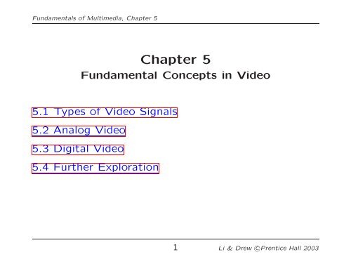
<strong>Fundamental</strong>s of Multimedia, Chapter 5Chapter 5<strong>Fundamental</strong> <strong>Concepts</strong> <strong>in</strong> <strong>Video</strong>5.1 Types of <strong>Video</strong> Signals5.2 Analog <strong>Video</strong>5.3 Digital <strong>Video</strong>5.4 Further Exploration1 Li & Drew c○Prentice Hall 2003
<strong>Fundamental</strong>s of Multimedia, Chapter 55.1 Types of <strong>Video</strong> SignalsComponent video• Component video: Higher-end video systems make use ofthree separate video signals for the red, green, and blue imageplanes. Each color channel is sent as a separate video signal.(a) Most computer systems use Component <strong>Video</strong>, with separatesignals for R, G, and B signals.(b) For any color separation scheme, Component <strong>Video</strong> givesthe best color reproduction s<strong>in</strong>ce there is no “crosstalk”between the three channels.(c) This is not the case for S-<strong>Video</strong> or Composite <strong>Video</strong>, discussednext. Component video, however, requires morebandwidth and good synchronization of the three components.2 Li & Drew c○Prentice Hall 2003
<strong>Fundamental</strong>s of Multimedia, Chapter 5Composite <strong>Video</strong> — 1 Signal• Composite video: color (“chrom<strong>in</strong>ance”) and <strong>in</strong>tensity(“lum<strong>in</strong>ance”) signals are mixed <strong>in</strong>to a s<strong>in</strong>gle carrier wave.a) Chrom<strong>in</strong>ance is a composition of two color components (I and Q,orUandV).b) In NTSC TV, e.g., I and Q are comb<strong>in</strong>ed <strong>in</strong>to a chroma signal, anda color subcarrier is then employed to put the chroma signal at thehigh-frequency end of the signal shared with the lum<strong>in</strong>ance signal.c) The chrom<strong>in</strong>ance and lum<strong>in</strong>ance components can be separated atthe receiver end and then the two color components can be furtherrecovered.d) When connect<strong>in</strong>g to TVs or VCRs, Composite <strong>Video</strong> uses only onewire and video color signals are mixed, not sent separately. The audioand sync signals are additions to this one signal.• S<strong>in</strong>ce color and <strong>in</strong>tensity are wrapped <strong>in</strong>to the same signal,some <strong>in</strong>terference between the lum<strong>in</strong>ance and chrom<strong>in</strong>ancesignals is <strong>in</strong>evitable.3 Li & Drew c○Prentice Hall 2003
<strong>Fundamental</strong>s of Multimedia, Chapter 5S-<strong>Video</strong> — 2 Signals• S-<strong>Video</strong>: as a compromise, (Separated video, or Supervideo,e.g., <strong>in</strong> S-VHS) uses two wires, one for lum<strong>in</strong>anceand another for a composite chrom<strong>in</strong>ance signal.• As a result, there is less crosstalk between the color <strong>in</strong>formationand the crucial gray-scale <strong>in</strong>formation.• The reason for plac<strong>in</strong>g lum<strong>in</strong>ance <strong>in</strong>to its own part of thesignal is that black-and-white <strong>in</strong>formation is most crucial forvisual perception.– In fact, humans are able to differentiate spatial resolution <strong>in</strong> grayscaleimages with a much higher acuity than for the color part ofcolor images.– As a result, we can send less accurate color <strong>in</strong>formation than mustbe sent for <strong>in</strong>tensity <strong>in</strong>formation — we can only see fairly large blobsof color, so it makes sense to send less color detail.4 Li & Drew c○Prentice Hall 2003
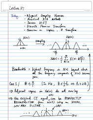
<strong>Fundamental</strong>s of Multimedia, Chapter 5PRUQSTFig. 5.1: Interlaced raster scanVc) Figure 5.1 shows the scheme used. First the solid (odd) l<strong>in</strong>es aretraced, P to Q, then R to S, etc., end<strong>in</strong>g at T; then the even fieldstarts at U and ends at V.d) The jump from Q to R, etc. <strong>in</strong> Figure 5.1 is called the horizontalretrace, dur<strong>in</strong>g which the electronic beam <strong>in</strong> the CRT is blanked.The jump from T to U or V to P is called the vertical retrace.6 Li & Drew c○Prentice Hall 2003
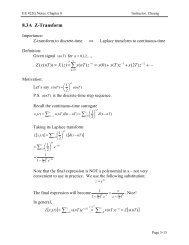
<strong>Fundamental</strong>s of Multimedia, Chapter 5• Because of <strong>in</strong>terlac<strong>in</strong>g, the odd and even l<strong>in</strong>es are displaced<strong>in</strong> time from each other — generally not noticeable exceptwhen very fast action is tak<strong>in</strong>g place on screen, when blurr<strong>in</strong>gmay occur.• For example, <strong>in</strong> the video <strong>in</strong> Fig. 5.2, the mov<strong>in</strong>g helicopteris blurred more than is the still background.7 Li & Drew c○Prentice Hall 2003
<strong>Fundamental</strong>s of Multimedia, Chapter 5(a)(b) (c) (d)Fig. 5.2:Interlaced scan produces two fields for each frame. (a) Thevideo frame, (b) Field 1, (c) Field 2, (d) Difference of Fields8 Li & Drew c○Prentice Hall 2003
<strong>Fundamental</strong>s of Multimedia, Chapter 5• S<strong>in</strong>ce it is sometimes necessary to change the frame rate,resize, or even produce stills from an <strong>in</strong>terlaced source video,various schemes are used to “de-<strong>in</strong>terlace” it.a) The simplest de-<strong>in</strong>terlac<strong>in</strong>g method consists of discard<strong>in</strong>gone field and duplicat<strong>in</strong>g the scan l<strong>in</strong>es of the other field.The <strong>in</strong>formation <strong>in</strong> one field is lost completely us<strong>in</strong>g thissimple technique.b) Other more complicated methods that reta<strong>in</strong> <strong>in</strong>formationfrom both fields are also possible.• Analog video use a small voltage offset from zero to <strong>in</strong>dicate“black”, and another value such as zero to <strong>in</strong>dicate the startof a l<strong>in</strong>e. For example, we could use a “blacker-than-black”zero signal to <strong>in</strong>dicate the beg<strong>in</strong>n<strong>in</strong>g of a l<strong>in</strong>e.9 Li & Drew c○Prentice Hall 2003
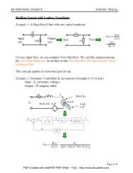
<strong>Fundamental</strong>s of Multimedia, Chapter 5White (0.714 V)Black (0.055 V)Blank (0 V)tSync (- 0.286 V)10.9 µsHoriz. retrace52.7 µsActive l<strong>in</strong>e signalFig. 5.3Electronic signal for one NTSC scan l<strong>in</strong>e.10 Li & Drew c○Prentice Hall 2003
<strong>Fundamental</strong>s of Multimedia, Chapter 5NTSC <strong>Video</strong>• NTSC (National Television System Committee) TV standardis mostly used <strong>in</strong> North America and Japan. It uses thefamiliar 4:3 aspect ratio (i.e., the ratio of picture width toits height) and uses 525 scan l<strong>in</strong>es per frame at 30 framesper second (fps).a) NTSC follows the <strong>in</strong>terlaced scann<strong>in</strong>g system, and each frame is divided<strong>in</strong>to two fields, with 262.5 l<strong>in</strong>es/field.b) Thus the horizontal sweep frequency is 525×29.97 ≈ 15, 734 l<strong>in</strong>es/sec,so that each l<strong>in</strong>e is swept out <strong>in</strong> 1/15.734 × 10 3 sec ≈ 63.6µsec.c) S<strong>in</strong>ce the horizontal retrace takes 10.9 µsec, this leaves 52.7 µsecfor the active l<strong>in</strong>e signal dur<strong>in</strong>g which image data is displayed (seeFig.5.3).11 Li & Drew c○Prentice Hall 2003
<strong>Fundamental</strong>s of Multimedia, Chapter 5• Fig. 5.4 shows the effect of “vertical retrace & sync” and“horizontal retrace & sync” on the NTSC video raster.Vertical retrace and syncHorizontal retrace and syncImage DataFig. 5.4: <strong>Video</strong> raster, <strong>in</strong>clud<strong>in</strong>g retrace and sync data12 Li & Drew c○Prentice Hall 2003
<strong>Fundamental</strong>s of Multimedia, Chapter 5a) Vertical retrace takes place dur<strong>in</strong>g 20 l<strong>in</strong>es reserved for control <strong>in</strong>formationat the beg<strong>in</strong>n<strong>in</strong>g of each field. Hence, the number of activevideo l<strong>in</strong>es per frame is only 485.b) Similarly, almost 1/6 of the raster at the left side is blanked forhorizontal retrace and sync. The non-blank<strong>in</strong>g pixels are called activepixels.c) S<strong>in</strong>ce the horizontal retrace takes 10.9 µsec, this leaves 52.7 µsecfor the active l<strong>in</strong>e signal dur<strong>in</strong>g which image data is displayed (seeFig.5.3).d) It is known that pixels often fall <strong>in</strong>-between the scan l<strong>in</strong>es. Therefore,even with non-<strong>in</strong>terlaced scan, NTSC TV is only capable of show<strong>in</strong>gabout 340 (visually dist<strong>in</strong>ct) l<strong>in</strong>es, i.e., about 70% of the 485 specifiedactive l<strong>in</strong>es. With <strong>in</strong>terlaced scan, this could be as low as 50%.13 Li & Drew c○Prentice Hall 2003
<strong>Fundamental</strong>s of Multimedia, Chapter 5• NTSC video is an analog signal with no fixed horizontal resolution.Therefore one must decide how many times to samplethe signal for display: each sample corresponds to one pixeloutput.• A “pixel clock” is used to divide each horizontal l<strong>in</strong>e of video<strong>in</strong>to samples. The higher the frequency of the pixel clock,the more samples per l<strong>in</strong>e there are.• Different video formats provide different numbers of samplesper l<strong>in</strong>e, as listed <strong>in</strong> Table 5.1.Table 5.1: Samples per l<strong>in</strong>e for various video formatsFormatSamples per l<strong>in</strong>eVHS 240S-VHS 400-425Betamax 500Standard 8 mm 300Hi-8 mm 42514 Li & Drew c○Prentice Hall 2003
<strong>Fundamental</strong>s of Multimedia, Chapter 5Color Model and Modulation of NTSC• NTSC uses the YIQ color model, and the technique of quadraturemodulation is employed to comb<strong>in</strong>e (the spectrallyoverlapped part of) I (<strong>in</strong>-phase) and Q (quadrature) signals<strong>in</strong>to a s<strong>in</strong>gle chroma signal C:C = I cos(F sc t) + Qs<strong>in</strong>(F sc t) (5.1)• This modulated chroma signal is also √ known as the colorsubcarrier, whose magnitude is I 2 + Q 2 , and phase istan −1 (Q/I). The frequency of C is F sc ≈ 3.58 MHz.• The NTSC composite signal is a further composition of thelum<strong>in</strong>ance signal Y and the chroma signal as def<strong>in</strong>ed below:composite = Y + C = Y + I cos(F sc t)+Qs<strong>in</strong>(F sc t) (5.2)15 Li & Drew c○Prentice Hall 2003
<strong>Fundamental</strong>s of Multimedia, Chapter 5• Fig. 5.5: NTSC assigns a bandwidth of 4.2 MHz to Y ,and only 1.6 MHz to I and 0.6 MHz to Q due to humans’<strong>in</strong>sensitivity to color details (high frequency color changes).6 MHz4.2 MHz0 1.25Y I and Q4.83 5.75PicturecarrierColorsubcarrierAudiosubcarrier6.0f (MHz)Fig. 5.5: Interleav<strong>in</strong>g Y and C signals <strong>in</strong> the NTSC spectrum.16 Li & Drew c○Prentice Hall 2003
<strong>Fundamental</strong>s of Multimedia, Chapter 5Decod<strong>in</strong>g NTSC Signals• The first step <strong>in</strong> decod<strong>in</strong>g the composite signal at the receiverside is the separation of Y and C.• After the separation of Y us<strong>in</strong>g a low-pass filter, the chromasignal C can be demodulated to extract the components Iand Q separately. To extract I:1. Multiply the signal C by 2 cos(F sc t), i.e.,C · 2cos(F sc t) = I ·2cos 2 (F sc t)+Q·2s<strong>in</strong>(F sc t)cos(F sc t)= I · (1 + cos(2F sc t)) + Q · 2s<strong>in</strong>(F sc t)cos(F sc t)= I + I · cos(2F sc t)+Q·s<strong>in</strong>(2F sc t).17 Li & Drew c○Prentice Hall 2003
<strong>Fundamental</strong>s of Multimedia, Chapter 52. Apply a low-pass filter to obta<strong>in</strong> I and discard the twohigher frequency (2F sc ) terms.• Similarly, Q can be extracted by first multiply<strong>in</strong>g C by 2 s<strong>in</strong>(F sc t)and then low-pass filter<strong>in</strong>g.18 Li & Drew c○Prentice Hall 2003
<strong>Fundamental</strong>s of Multimedia, Chapter 5• The NTSC bandwidth of 6 MHz is tight. Its audio subcarrierfrequency is 4.5 MHz. The Picture carrier is at 1.25 MHz,which places the center of the audio band at 1.25+4.5 =5.75MHz <strong>in</strong> the channel (Fig. 5.5). But notice that the color isplaced at 1.25 + 3.58 = 4.83 MHz.• So the audio is a bit too close to the color subcarrier — acause for potential <strong>in</strong>terference between the audio and colorsignals. It was largely due to this reason that the NTSC colorTV actually slowed down its frame rate to 30×1, 000/1, 001 ≈29.97 fps.• As a result, the adopted NTSC color subcarrier frequency isslightly lowered tof sc =30×1,000/1, 001 × 525 × 227.5 ≈ 3.579545MHz,where 227.5 is the number of color samples per scan l<strong>in</strong>e <strong>in</strong>NTSC broadcast TV.19 Li & Drew c○Prentice Hall 2003
<strong>Fundamental</strong>s of Multimedia, Chapter 5PAL <strong>Video</strong>• PAL (Phase Alternat<strong>in</strong>g L<strong>in</strong>e) is a TV standard widelyused <strong>in</strong> Western Europe, Ch<strong>in</strong>a, India, and many other partsof the world.• PAL uses 625 scan l<strong>in</strong>es per frame, at 25 frames/second,with a 4:3 aspect ratio and <strong>in</strong>terlaced fields.(a) PAL uses the YUV color model. It uses an 8 MHz channel andallocates a bandwidth of 5.5 MHz to Y, and 1.8 MHz each to U andV. The color subcarrier frequency is f sc ≈ 4.43 MHz.(b) In order to improve picture quality, chroma signals have alternatesigns (e.g., +U and -U) <strong>in</strong> successive scan l<strong>in</strong>es, hence the name“Phase Alternat<strong>in</strong>g L<strong>in</strong>e”.(c) This facilitates the use of a (l<strong>in</strong>e rate) comb filter at the receiver— the signals <strong>in</strong> consecutive l<strong>in</strong>es are averaged so as to cancel thechroma signals (that always carry opposite signs) for separat<strong>in</strong>g Yand C and obta<strong>in</strong><strong>in</strong>g high quality Y signals.20 Li & Drew c○Prentice Hall 2003
<strong>Fundamental</strong>s of Multimedia, Chapter 5SECAM <strong>Video</strong>• SECAM stands for Système Electronique Couleur Avec Mémoire,the third major broadcast TV standard.• SECAM also uses 625 scan l<strong>in</strong>es per frame, at 25 frames persecond, with a 4:3 aspect ratio and <strong>in</strong>terlaced fields.• SECAM and PAL are very similar. They differ slightly <strong>in</strong> theircolor cod<strong>in</strong>g scheme:(a) In SECAM, U and V signals are modulated us<strong>in</strong>g separatecolor subcarriers at 4.25 MHz and 4.41 MHz respectively.(b) They are sent <strong>in</strong> alternate l<strong>in</strong>es, i.e., only one of the U orV signals will be sent on each scan l<strong>in</strong>e.21 Li & Drew c○Prentice Hall 2003
<strong>Fundamental</strong>s of Multimedia, Chapter 5• Table 5.2 gives a comparison of the three major analogbroadcast TV systems.Table 5.2: Comparison of Analog Broadcast TV SystemsFrame #of Total BandwidthTV System Rate Scan Channel Allocation (MHz)(fps) L<strong>in</strong>es Width (MHz) Y IorU QorVNTSC 29.97 525 6.0 4.2 1.6 0.6PAL 25 625 8.0 5.5 1.8 1.8SECAM 25 625 8.0 6.0 2.0 2.022 Li & Drew c○Prentice Hall 2003
<strong>Fundamental</strong>s of Multimedia, Chapter 55.3 Digital <strong>Video</strong>• The advantages of digital representation for video are many.For example:(a) <strong>Video</strong> can be stored on digital devices or <strong>in</strong> memory, readyto be processed (noise removal, cut and paste, etc.), and<strong>in</strong>tegrated to various multimedia applications;(b) Direct access is possible, which makes nonl<strong>in</strong>ear videoedit<strong>in</strong>g achievable as a simple, rather than a complex,task;(c) Repeated record<strong>in</strong>g does not degrade image quality;(d) Ease of encryption and better tolerance to channel noise.23 Li & Drew c○Prentice Hall 2003
<strong>Fundamental</strong>s of Multimedia, Chapter 5Chroma Subsampl<strong>in</strong>g• S<strong>in</strong>ce humans see color with much less spatial resolution thanthey see black and white, it makes sense to “decimate” thechrom<strong>in</strong>ance signal.• Interest<strong>in</strong>g (but not necessarily <strong>in</strong>formative!)arisen to label the different schemes used.names have• To beg<strong>in</strong> with, numbers are given stat<strong>in</strong>g how many pixelvalues, per four orig<strong>in</strong>al pixels, are actually sent:(a) The chroma subsampl<strong>in</strong>g scheme “4:4:4” <strong>in</strong>dicates thatno chroma subsampl<strong>in</strong>g is used: each pixel’s Y, Cb andCr values are transmitted, 4 for each of Y, Cb, Cr.24 Li & Drew c○Prentice Hall 2003
<strong>Fundamental</strong>s of Multimedia, Chapter 5(b) The scheme “4:2:2” <strong>in</strong>dicates horizontal subsampl<strong>in</strong>g ofthe Cb, Cr signals by a factor of 2. That is, of four pixelshorizontally labelled as 0 to 3, all four Ys are sent, andevery two Cb’s and two Cr’s are sent, as (Cb0, Y0)(Cr0,Y1)(Cb2, Y2)(Cr2, Y3)(Cb4, Y4), and so on (or averag<strong>in</strong>gis used).(c) The scheme “4:1:1” subsamples horizontally by a factorof 4.(d) The scheme “4:2:0” subsamples <strong>in</strong> both the horizontaland vertical dimensions by a factor of 2. Theoretically, anaverage chroma pixel is positioned between the rows andcolumns as shown Fig.5.6.• Scheme 4:2:0 along with other schemes is commonly used <strong>in</strong>JPEG and MPEG (see later chapters <strong>in</strong> Part 2).25 Li & Drew c○Prentice Hall 2003
<strong>Fundamental</strong>s of Multimedia, Chapter 54:4:4 4:2:24:1:14:2:0Pixel with only Y valuePixel with only Cr and Cb valuesPixel with Y, Cr, and Cb valuesFig. 5.6: Chroma subsampl<strong>in</strong>g.26 Li & Drew c○Prentice Hall 2003
<strong>Fundamental</strong>s of Multimedia, Chapter 5CCIR Standards for Digital <strong>Video</strong>• CCIR is the Consultative Committee for International Radio,and one of the most important standards it has produced isCCIR-601, for component digital video.– This standard has s<strong>in</strong>ce become standard ITU-R-601, an<strong>in</strong>ternational standard for professional video applications— adopted by certa<strong>in</strong> digital video formats <strong>in</strong>clud<strong>in</strong>g thepopular DV video.• Table 5.3 shows some of the digital video specifications, allwith an aspect ratio of 4:3. The CCIR 601 standard uses an<strong>in</strong>terlaced scan, so each field has only half as much verticalresolution (e.g., 240 l<strong>in</strong>es <strong>in</strong> NTSC).27 Li & Drew c○Prentice Hall 2003
<strong>Fundamental</strong>s of Multimedia, Chapter 5• CIF stands for Common Intermediate Format specified bythe CCITT.(a) The idea of CIF is to specify a format for lower bitrate.(b) CIF is about the same as VHS quality. It uses a progressive(non-<strong>in</strong>terlaced) scan.(c) QCIF stands for “Quarter-CIF”. All the CIF/QCIF resolutionsare evenly divisible by 8, and all except 88 aredivisible by 16; this provides convenience for block-basedvideo cod<strong>in</strong>g <strong>in</strong> H.261 and H.263, discussed later <strong>in</strong> Chapter10.28 Li & Drew c○Prentice Hall 2003
<strong>Fundamental</strong>s of Multimedia, Chapter 5(d) Note, CIF is a compromise of NTSC and PAL <strong>in</strong> that itadopts the ‘NTSC frame rate and half of the number ofactive l<strong>in</strong>es as <strong>in</strong> PAL.Table 5.3: Digital video specificationsCCIR 601 CCIR 601 CIF QCIF525/60 625/50NTSC PAL/SECAMLum<strong>in</strong>ance resolution 720 × 480 720 × 576 352 × 288 176 × 144Chrom<strong>in</strong>ance resolution 360 × 480 360 × 576 176 × 144 88 × 72Color Subsampl<strong>in</strong>g 4:2:2 4:2:2 4:2:0 4:2:0Aspect Ratio 4:3 4:3 4:3 4:3Fields/sec 60 50 30 30Interlaced Yes Yes No No29 Li & Drew c○Prentice Hall 2003
<strong>Fundamental</strong>s of Multimedia, Chapter 5HDTV (High Def<strong>in</strong>ition TV)• The ma<strong>in</strong> thrust of HDTV (High Def<strong>in</strong>ition TV) is not to<strong>in</strong>crease the “def<strong>in</strong>ition” <strong>in</strong> each unit area, but rather to<strong>in</strong>crease the visual field especially <strong>in</strong> its width.(a) The first generation of HDTV was based on an analog technologydeveloped by Sony and NHK <strong>in</strong> Japan <strong>in</strong> the late 1970s.(b) MUSE (MUltiple sub-Nyquist Sampl<strong>in</strong>g Encod<strong>in</strong>g) was an improvedNHK HDTV with hybrid analog/digital technologies that was put <strong>in</strong>use <strong>in</strong> the 1990s. It has 1,125 scan l<strong>in</strong>es, <strong>in</strong>terlaced (60 fields persecond), and 16:9 aspect ratio.(c) S<strong>in</strong>ce uncompressed HDTV will easily demand more than 20 MHzbandwidth, which will not fit <strong>in</strong> the current 6 MHz or 8 MHz channels,various compression techniques are be<strong>in</strong>g <strong>in</strong>vestigated.(d) It is also anticipated that high quality HDTV signals will be transmittedus<strong>in</strong>g more than one channel even after compression.30 Li & Drew c○Prentice Hall 2003
<strong>Fundamental</strong>s of Multimedia, Chapter 5• A brief history of HDTV evolution:(a) In 1987, the FCC decided that HDTV standards must be compatiblewith the exist<strong>in</strong>g NTSC standard and be conf<strong>in</strong>ed to the exist<strong>in</strong>g VHF(Very High Frequency) and UHF (Ultra High Frequency) bands.(b) In 1990, the FCC announced a very different <strong>in</strong>itiative, i.e., its preferencefor a full-resolution HDTV, and it was decided that HDTVwould be simultaneously broadcast with the exist<strong>in</strong>g NTSC TV andeventually replace it.(c) Witness<strong>in</strong>g a boom of proposals for digital HDTV, the FCC madea key decision to go all-digital <strong>in</strong> 1993. A “grand alliance” wasformed that <strong>in</strong>cluded four ma<strong>in</strong> proposals, by General Instruments,MIT, Zenith, and AT&T, and by Thomson, Philips, Sarnoff and others.(d) This eventually led to the formation of the ATSC (Advanced TelevisionSystems Committee) — responsible for the standard for TVbroadcast<strong>in</strong>g of HDTV.(e) In 1995 the U.S. FCC Advisory Committee on Advanced TelevisionService recommended that the ATSC Digital Television Standard beadopted.31 Li & Drew c○Prentice Hall 2003
<strong>Fundamental</strong>s of Multimedia, Chapter 5• The standard supports video scann<strong>in</strong>g formats shown <strong>in</strong> Table5.4. In the table, “I” mean <strong>in</strong>terlaced scan and “P”means progressive (non-<strong>in</strong>terlaced) scan.Table 5.4: Advanced Digital TV formats supported by ATSC# of Active # of Active Aspect Ratio Picture RatePixels per l<strong>in</strong>eL<strong>in</strong>es1,920 1,080 16:9 60I 30P 24P1,280 720 16:9 60P 30P 24P704 480 16:9 & 4:3 60I 60P 30P 24P640 480 4:3 60I 60P 30P 24P32 Li & Drew c○Prentice Hall 2003
<strong>Fundamental</strong>s of Multimedia, Chapter 5• For video, MPEG-2 is chosen as the compression standard.For audio, AC-3 is the standard. It supports the so-called 5.1channel Dolby surround sound, i.e., five surround channelsplus a subwoofer channel.• The salient difference between conventional TV and HDTV:(a) HDTV has a much wider aspect ratio of 16:9 <strong>in</strong>stead of 4:3.(b) HDTV moves toward progressive (non-<strong>in</strong>terlaced) scan. The rationaleis that <strong>in</strong>terlac<strong>in</strong>g <strong>in</strong>troduces serrated edges to mov<strong>in</strong>g objects andflickers along horizontal edges.33 Li & Drew c○Prentice Hall 2003
<strong>Fundamental</strong>s of Multimedia, Chapter 5• The FCC has planned to replace all analog broadcast serviceswith digital TV broadcast<strong>in</strong>g by the year 2006. The servicesprovided will <strong>in</strong>clude:– SDTV (Standard Def<strong>in</strong>ition TV): the current NTSC TV or higher.– EDTV (Enhanced Def<strong>in</strong>ition TV): 480 active l<strong>in</strong>es or higher, i.e.,the third and fourth rows <strong>in</strong> Table 5.4.– HDTV (High Def<strong>in</strong>ition TV): 720 active l<strong>in</strong>es or higher.34 Li & Drew c○Prentice Hall 2003
<strong>Fundamental</strong>s of Multimedia, Chapter 55.4 Further Exploration−→ L<strong>in</strong>k to Further Exploration for Chapter 5.• L<strong>in</strong>ks given for this Chapter on the text website <strong>in</strong>clude:– Tutorials on NTSC television– The official ATSC home page– The latest news on the digital TV front– Introduction to HDTV– The official FCC (Federal Communications Commission)home page35 Li & Drew c○Prentice Hall 2003