strata and debris (resulting from <strong>the</strong> pile shaft excavation) located below and at <strong>the</strong> pile toe, thus mobilising<strong>the</strong> full pile end bearing at a smaller displacement. This is a critical aspect when using large diameter piles.The peak pile end-bearing resistance may be assumed to be mobilised at 10% <strong>of</strong> <strong>the</strong> pile diameter (i.e. 300mm here), at which displacement shear will already have occurred along <strong>the</strong> shaft, thus providing very limitedresidual resistance, and <strong>the</strong> pile settlement will also already be excessive. Base grouting will also restore <strong>the</strong>original in situ strength <strong>of</strong> <strong>the</strong> soil which was expected to be affected by <strong>the</strong> anticipated lengthy excavationunder bentonite slurry <strong>of</strong> <strong>the</strong> deep, large diameter pile shafts. A particular arrangement <strong>of</strong> six U-shaped“tubes-à-manchette” cast into <strong>the</strong> toe <strong>of</strong> <strong>the</strong> pile was adopted to base grout a substantial proportion <strong>of</strong> <strong>the</strong>large pile footprint. The effectiveness <strong>of</strong> <strong>the</strong> base grouting was verified by comparing <strong>the</strong> results <strong>of</strong> three basegrouted test piles to <strong>the</strong> un-grouted test pile at Pier 3. The compaction grouting was found to be very effectiveinrestoring and indeed improving <strong>the</strong> original in situ soil resistance. The pile testing also showed that some <strong>of</strong><strong>the</strong> grout injected at <strong>the</strong> toe <strong>of</strong> <strong>the</strong> piles had randomly migrated upwards from <strong>the</strong> pile toe along <strong>the</strong> shaft interface<strong>of</strong>ten substantially improving <strong>the</strong> frictional resistance <strong>of</strong> <strong>the</strong> bottom 3-4 m <strong>of</strong> <strong>the</strong> piles. The advantages <strong>of</strong>using compaction grouting were also confirmed by comparing <strong>the</strong> sonic logging integrity test results for <strong>the</strong>non-base-grouted test pile at Pier 3 to <strong>the</strong> o<strong>the</strong>r three base-grouted test piles. The non-base-grouted pileshowed a “s<strong>of</strong>t” pile toe compared to <strong>the</strong> “sound” pile toes <strong>of</strong> <strong>the</strong> o<strong>the</strong>r three piles. This was despite <strong>the</strong> basegroutedpiles being substantially deeper and <strong>the</strong>refore comparatively more likely to suffer this problem due togreater elastic expansion <strong>of</strong> clay and granular strata, plastic expansion <strong>of</strong> expansive clayey strata due to rehydrationand <strong>the</strong> accumulation <strong>of</strong> a greater thickness <strong>of</strong> debris at <strong>the</strong> base prior to concrete placement.4.3 Pile TestingThe definitive design <strong>of</strong> <strong>the</strong> main bridge piers incorporated four 3 m diameter bored cast in situ vertical pilesat each pier, with length ranging from 62.0 m to 77.0 m (from base <strong>of</strong> pile cap), and able to withstand serviceloads <strong>of</strong> between 45 MN and 53 MN. The two abutments and <strong>the</strong> approach viaduct were founded on a total <strong>of</strong>thirty-six 1.5 m diameter bored cast in situ vertical piles <strong>of</strong> maximum length <strong>of</strong> 54.0 m (from ground level)able to withstand service loads <strong>of</strong> up to 4.2 MN.The preliminary pile design was validated and optimised bycomparison with <strong>the</strong> data derived from four vertical bored cast in situ reinforced concrete test piles. Thesepiles were located in very close proximity to three <strong>of</strong> <strong>the</strong> four main bridge piers (Pier 7, 8 and 10) and oneclose to <strong>the</strong> approach viaduct piles at Pier 3. The test piles were <strong>of</strong> smaller diameter (i.e. 1.5 m) compared to<strong>the</strong> main pier working piles and ranged in length from 52.3 m to 74.6 m (from <strong>the</strong> base <strong>of</strong> pile cap). For technical,practical and health and safety reasons, <strong>the</strong> pile testing was carried out using a self balancing hydraulicjack-up system (similar to <strong>the</strong> Osterberg-cell ® ).The test piles were fully instrumented with strain gauges ando<strong>the</strong>r monitoring apparatus in order to obtain a breakdown <strong>of</strong> <strong>the</strong> pile resistance and displacement along <strong>the</strong>various sections <strong>of</strong> <strong>the</strong> pile shaft and in end-bearing. The pile testing regime gave very clear and consistentestimates <strong>of</strong> <strong>the</strong> resistance <strong>of</strong> <strong>the</strong> soil, which were <strong>the</strong>n correlated with <strong>the</strong> laboratory geotechnical and SPTdata.4.4 Trial PileGiven <strong>the</strong> unusually large diameter <strong>of</strong> <strong>the</strong> piles, <strong>the</strong> pile length and <strong>the</strong> site logistics it was considered necessaryto construct a full size trial pile which was located close to Pier 7. This was similar in construction to <strong>the</strong>anticipated working piles, including steel reinforcement cages, sonic logging tubes and base grouting. Thepile was not load-tested both because <strong>of</strong> <strong>the</strong> practical difficulties (given its capacity) and due to <strong>the</strong> very satisfactoryand consistent results already obtained for <strong>the</strong> test piles. The construction <strong>of</strong> <strong>the</strong> trial pile proved to beextremely valuable as it provided considerable information about <strong>the</strong> constructability aspects including drilling<strong>of</strong> <strong>the</strong> shafts, cleaning <strong>of</strong> <strong>the</strong> shaft base, concreting operations, base grouting and construction timing.5 SUBSTRUCTURE STRUCTURAL DESIGN5.1 <strong>Design</strong> principlesAASHTO LRFD (2004) requires that bridge foundations are designed using limit state principles to resistservice loads, ultimate (factored service) loads and extreme loads (e.g. seismic and ship impact). The workingpiles were designed to transfer into <strong>the</strong> ground <strong>the</strong> vertical and horizontal loads arising from self weight <strong>of</strong> <strong>the</strong>structure, soil downdrag on piles, construction effects e.g. out <strong>of</strong> balance loads from cantilever construction,live loading, wind, ship impact hydrodynamic flow and seismic action. As experienced on o<strong>the</strong>r long spanconcrete bridges in <strong>Bangladesh</strong> and India (e.g. Castelli& Wilkins 2004, Farooq& Barr 1999), <strong>the</strong> design <strong>of</strong><strong>the</strong> bridge substructure is strongly conditioned by seismic effects. These are both responsible for additional260
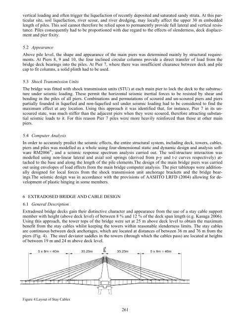
vertical loading and <strong>of</strong>ten trigger <strong>the</strong> liquefaction <strong>of</strong> recently deposited and saturated sandy strata. At this particularsite, soil liquefaction, river scour, and river dredging, may locally affect <strong>the</strong> upper 30 m embeddedlength <strong>of</strong> piles. This soil cannot <strong>the</strong>refore be relied upon to permanently provide full lateral and vertical resistance.Piles consequently had to be proportioned with due regard to <strong>the</strong> effects <strong>of</strong> slenderness, deck displacementand pier fixity.5.2 AppearanceAbove pile level, <strong>the</strong> shape and appearance <strong>of</strong> <strong>the</strong> main piers was determined mainly by structural requirements.At Piers 8, 9 and 10, <strong>the</strong> four inclined circular columns provide a direct transfer <strong>of</strong> load from <strong>the</strong>bridge deck bearings into <strong>the</strong> piles. At Pier 7, where <strong>the</strong>re was insufficient clearance between deck and pilecap to fit columns, a solid plinth had to be used.5.3 Shock Transmission UnitsThe bridge was fitted with shock transmission units (STU) at each main pier to lock <strong>the</strong> deck to <strong>the</strong> substructureunder seismic loading. These permit <strong>the</strong> horizontal seismic inertial forces to be resisted by shear andbending in <strong>the</strong> piles <strong>of</strong> all piers. Combinations and permutations <strong>of</strong> scoured and un-scoured piers and pierspartially founded in liquefied and non-liquefied soil under seismic loading had to be considered to find <strong>the</strong>maximum effect at any location. Using this approach it was identified that, for instance, Pier 7 in its unscouredstate, was much stiffer than <strong>the</strong> adjacent piers when <strong>the</strong>y were scoured, <strong>the</strong>refore attracting substantialseismic loads to it. For this reason Pier 7 piles were more heavily reinforced than those at o<strong>the</strong>r mainpiers.5.4 Computer AnalysisIn order to accurately predict <strong>the</strong> seismic effects, <strong>the</strong> entire structural system, including deck, towers, cables,piers and piles was modelled as a whole using four-dimensional static and dynamic design and analysis s<strong>of</strong>twareRM2006 ® , and a seismic response spectrum analysis carried out. The soil/structure interaction wasmodelled using non-linear lateral and axial soil springs (derived from p-y and t-z curves respectively) attachedto <strong>the</strong> base and along <strong>the</strong> length <strong>of</strong> <strong>the</strong> pile elements.The design <strong>of</strong> <strong>the</strong> main bridge piers was carriedout using envelopes <strong>of</strong> load effects from <strong>the</strong> main bridge computer analysis. The pier tabletops were additionallydesigned for local forces from <strong>the</strong> shock transmission unit anchorage brackets and <strong>the</strong> bridge bearings.Theseismic design was in accordance with <strong>the</strong> provisions <strong>of</strong> AASHTO LRFD (2004) allowing for development<strong>of</strong> plastic hinging in some members.6 EXTRADOSED BRIDGE AND CABLE DESIGN6.1 General DescriptionExtradosed bridge decks gain <strong>the</strong>ir distinctive character and appearance from <strong>the</strong> use <strong>of</strong> a stay cable supportmember with height (above deck level) <strong>of</strong> between 8 % and 12 % <strong>of</strong> <strong>the</strong> deck span length (e.g. Kasuga 2006).Using this approach, <strong>the</strong> tower tops <strong>of</strong> <strong>the</strong> bridge were set at 25 m above deck level to obtain <strong>the</strong> maximumbenefit from <strong>the</strong> stay cables whilst keeping <strong>the</strong> towers within reasonable slenderness limits. The stay cablesare continuous between deck anchorages, which are located at distances <strong>of</strong> between 36 m and 76 m from <strong>the</strong>piers (Fig. 4). The steel deviator saddles in <strong>the</strong> towers (through which <strong>the</strong> cables pass) are located at heights<strong>of</strong> between 19 m and 24 m above deck level.Figure 4.Layout <strong>of</strong> Stay Cables261