- Page 1 and 2: OPTICAL CHARACTERISATION OF RARE-EA
- Page 3: Table of ContentsAcknowledgementsLi
- Page 6 and 7: AcknowledgementsThe work in this th
- Page 8 and 9: viiiList of Publications[1] J. Ward
- Page 10 and 11: xTo the best of our knowledge, this
- Page 12 and 13: xiiWDMWGMZBNAZBLALiPZBLANWavelength
- Page 14 and 15: xiv1.6 Fundamental light-matter int
- Page 16 and 17: xvi3.8 Gain coecient for dierent po
- Page 18 and 19: xviii4.9 Fluorescence slopes and sp
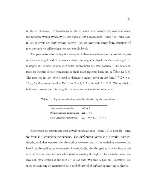
- Page 20 and 21: xxList of Tables1.1 Rigorous select
- Page 22 and 23: 2device size (typically < 200 m dia
- Page 24 and 25: 4a wider range of materials can exh
- Page 26 and 27: 6in Chapter 2: angle-polished bres
- Page 28 and 29: 81.2 Whispering Gallery ModesWhispe
- Page 30 and 31: 10where j l (h (1)l) are spherical
- Page 32 and 33: 12(a)(b)Figure 1.2: Calculated inte
- Page 34 and 35: 14parameter, x nl , up to order =
- Page 36 and 37: 16coecient of water. There is an a
- Page 38 and 39: 18(a) Silica glass(b) ZBLALiP glass
- Page 40 and 41: 20eld (Eqn. 1.2) over a quantisatio
- Page 44 and 45: 241.9 Radiative Emission RatesIn th
- Page 46 and 47: 261.10 Material Loss Mechanisms in
- Page 48 and 49: 28Chapter 2Fabrication of and Coupl
- Page 50 and 51: 30Figure 2.1: Microsphere fabricati
- Page 52 and 53: 32Figure 2.3:Schematic of (a) taper
- Page 54 and 55: 34Figure 2.4: Calculated polish ang
- Page 56 and 57: 36bre, the exact electric eld equat
- Page 58 and 59: 38Figure 2.6: Poynting vector for a
- Page 60 and 61: 40a few dozen tapered bres.As an al
- Page 62 and 63: 42Figure 2.7: Schematic of the tape
- Page 64 and 65: 44Figure 2.8: Taper prole for a 3 m
- Page 66 and 67: 46taper angle, the light in the pro
- Page 68 and 69: 48Figure 2.10: Optical micrograph o
- Page 70 and 71: 50controlled. The discrete step-siz
- Page 72 and 73: 52In recent years, much eort has be
- Page 74 and 75: 543.2 ZBLALiP Material PropertiesWe
- Page 76 and 77: 56Figure 3.3: Er 3+ energy level di
- Page 78 and 79: 58(Avanex, 1998 PLM) with a spectra
- Page 80 and 81: 60Figure 3.6: 66 m diameter microsp
- Page 82 and 83: 62(a) C-band(b) Pump bandFigure 3.7
- Page 84 and 85: 64as Judd-Ofelt (JO) analysis [72]-
- Page 86 and 87: 66The total spontaneous radiative t
- Page 88 and 89: 68Table 3.2: Predicted radiative tr
- Page 90 and 91: 70Figure 3.9: Observed Er 3+ :ZBLAL
- Page 92 and 93:
72pumping at 637 nm [77]. The same
- Page 94 and 95:
74Figure 3.10: Calculated fraction
- Page 96 and 97:
76Figure 3.11: Light in-Light out l
- Page 98 and 99:
78representing the Q of the cavity.
- Page 100 and 101:
80Figure 3.13: Quality factor measu
- Page 102 and 103:
82Chapter 4Thermally Induced Optica
- Page 104 and 105:
84especially benecial for C-band la
- Page 106 and 107:
86note three distinct emission band
- Page 108 and 109:
88therefore a combination of the in
- Page 110 and 111:
90This is close to the value of 2.1
- Page 112 and 113:
92Figure 4.4: Lasing spectrum for a
- Page 114 and 115:
94Figure 4.6: Intensity bistability
- Page 116 and 117:
96Figure 4.7: Chromatic switching f
- Page 118 and 119:
98equation, given byl = 2n s d 1 +
- Page 120 and 121:
100Figure 4.9: Fluorescence slopes
- Page 122 and 123:
102and the Kerr eect immediately, b
- Page 124 and 125:
104a precise setting for each spher
- Page 126 and 127:
106Figure 4.11: Graphical descripti
- Page 128 and 129:
108explanation for the peak in the
- Page 130 and 131:
110and the associated wheatstone br
- Page 132 and 133:
112performance have made them an in
- Page 134 and 135:
114laser slightly above threshold.
- Page 136 and 137:
116range is shown in Fig. 5.3(a). S
- Page 138 and 139:
118Chapter 6ConclusionsThis project
- Page 140 and 141:
120work. The reason for choosing 80
- Page 142 and 143:
122Appendix ASpectral Characterisat
- Page 144 and 145:
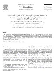
In this paper we will give an overv
- Page 146 and 147:
1.:1.21.21.11.10.90.60.70.60.90.60.
- Page 148 and 149:
⎥⎦2.2 Mode matching between a m
- Page 150 and 151:
Puill lengtln (iuniuncurrents or ot
- Page 152 and 153:
1.6x10 -71.4x10 -7IOG-2intensity (a
- Page 154 and 155:
134Appendix BA Heat-and-Pull Rig fo
- Page 156 and 157:
083105-2 Ward et al. Rev. Sci. Inst
- Page 158 and 159:
083105-4 Ward et al. Rev. Sci. Inst
- Page 160 and 161:
140Appendix CUpconversion Channels
- Page 162 and 163:
2 The European Physical Journal App
- Page 164 and 165:
4 The European Physical Journal App
- Page 166 and 167:
6 The European Physical Journal App
- Page 168 and 169:
8 The European Physical Journal App
- Page 170 and 171:
150
- Page 172 and 173:
152
- Page 174 and 175:
JOURNAL OF APPLIED PHYSICS 102, 023
- Page 176 and 177:
023104-3 Ward et al. J. Appl. Phys.
- Page 178 and 179:
023104-5 Ward et al. J. Appl. Phys.
- Page 180 and 181:
023104-7 Ward et al. J. Appl. Phys.
- Page 182 and 183:
162
- Page 184 and 185:
164
- Page 186 and 187:
166
- Page 188 and 189:
168
- Page 190 and 191:
Figure F.1: Electrical wiring diagr
- Page 192 and 193:
172[9] J. Z. Zhang and R. K. Chang.
- Page 194 and 195:
174[28] C. C. Lam, P. T. Leung and
- Page 196 and 197:
176[45] F. Le Kien, J. Q. Liang, K.
- Page 198 and 199:
178[63] M.-F. Joubert. \Photon aval
- Page 200 and 201:
180[81] A. Biswas, G. S. Maciel, C.
- Page 202 and 203:
182[98] M. Ajroud, M. Haouari, H. B
- Page 204:
184[116] L. Ricci, M. Weidemuller,