VFD-F (CURVE).cdr
VFD-F (CURVE).cdr
VFD-F (CURVE).cdr

Create successful ePaper yourself
Turn your PDF publications into a flip-book with our unique Google optimized e-Paper software.
PrefaceThank you for choosing DELTA’s high-performance <strong>VFD</strong>-F Series. <strong>VFD</strong>-F Series aremanufactured by adopting high-quality components, material and incorporating the latestmicroprocessor technology available.<strong>VFD</strong>-F Series Getting StartedThis manual will be helpful in the installation, parameter setting, troubleshooting, and dailymaintenance of the AC motor drives. To guarantee safe operation of the equipment, readthe following safety guidelines before connecting power to the AC drives. Keep thisoperating manual handy and distribute to all users for reference.! WARNING! Always read this manual thoroughly before using <strong>VFD</strong>-F series AC Motor Drives.! DANGER! AC input power must be disconnected before any maintenance. Do not connector disconnect wires and connectors while power is applied to the circuit. Maintenance mustbe performed by qualified technicians.! CAUTION! There are highly sensitive MOS components on the printed circuit boards.These components are especially sensitive to static electricity. To avoid damage to thesecomponents, do not touch these components or the circuit boards with metal objects oryour bare hands.! DANGER! A charge may still remain in the DC-link capacitor with hazardous voltages evenif the power has been turned off. To avoid personal injury, do not remove the cover of theAC drive until all “DISPLAY LED” lights on the digital keypad are off. Please note that thereare live components exposed within the AC drive. Do not touch these live parts.! CAUTION! Ground the <strong>VFD</strong>-F using the ground terminal. The grounding method mustcomply with the laws of the country where the AC drive is to be installed. Refer to BasicWiring Diagram.! DANGER! The AC drive may be destroyed beyond repair if incorrect cables are connectedto the input/output terminals. Never connect the AC drive output terminals U/T1, V/T2, andW/T3 directly to the AC main circuit power supply.! CAUTION! The final enclosures of the AC drive must comply with EN50178. (Live partsshall be arranged in enclosures or located behind barriers that meet at least therequirements of the Protective Type IP20. The top surface of the enclosures or barrier thatis easily accessible shall meet at least the requirements of the Protective Type IP40).(<strong>VFD</strong>-F series corresponds with this regulation.)! CAUTION! The rated voltage for the AC motor drive must be ≤ 240V for 230V models (≤480V for 460V models) and the mains supply current capacity must be ≤ 5000A RMS(≤10000A RMS for the ≥ 40hp (30kW) models)CAUTION! Heat sink may heat up over 70 o C (158 o F), during the operation. Do not touchthe heat sink.DELTA ELECTRONICS, INC. ALL RIGHTS RESERVED
<strong>VFD</strong>-F SeriesTABLE OF CONTENTSCHAPTER 1 RECEIVING AND INSPECTIONS1.1 Nameplate Information ........................................................................ 1 - 11.2 Model Explanation ............................................................................... 1 - 11.3 Serial Number Explanation.................................................................. 1 - 2CHAPTER 2 STORAGE AND INSTALLATION2.1 Storage................................................................................................. 2 - 12.2 Installation............................................................................................ 2 - 2CHAPTER 3 WIRING3.1 Basic Wiring Diagram .......................................................................... 3 - 23.2 Terminal Explanation ........................................................................... 3 - 53.3 Control Terminal Explanation............................................................... 3 - 53.4 Main Circuit Wiring ............................................................................. 3 - 73.5 Wiring Notes ........................................................................................ 3-163.6 Motor Operation Precautions .............................................................. 3-18CHAPTER 4 DIGITAL KEYPAD OPERATION4.1 <strong>VFD</strong>-PU01 ........................................................................................... 4 - 14.2 KPF-CC01 ........................................................................................... 4 - 5CHAPTER 5 DESCRIPTION OF PARAMETER SETTINGS5.1 Group 0: AC Drive Status Parameters................................................. 5 - 15.2 Group 1: Basic Parameters ................................................................. 5 - 4DELTA ELECTRONICS, INC. ALL RIGHTS RESERVED
<strong>VFD</strong>-F Series5.3 Group 2: Operation Method Parameters............................................. 5 - 95.4 Group 3: Output Function Parameters ................................................ 5-155.5 Group 4: Input Function Parameters................................................... 5-195.6 Group 5: Multi-step Speed Frequency Parameters............................. 5-245.7 Group 6: Protection Parameters.......................................................... 5-305.8 Group 7: AC Drive and Motor Parameters .......................................... 5-365.9 Group 8: Special Parameters .............................................................. 5-395.10 Group 9: Communication Parameters............................................... 5-455.11 Group 10: PID Control Parameters ................................................... 5-605.12 Group 11: Fan and Pump Control Parameters.................................. 5-63CHAPTER 6 MAINTENANCE AND INSPECTIONS6.1 Periodic Inspection .............................................................................. 6 - 16.2 Periodic Maintenance .......................................................................... 6 - 1CHAPTER 7 TROUBLESHOOTING AND FAULT INFORMATION........... 7 - 1CHAPTER 8 SUMMARY OF PARAMETER SETTINGS ............................ 8 - 1APPENDIX A SPECIFICATIONS ................................................................ A - 1APPENDIX B ACCESSORIESB.1 All Braking Resistors & Braking Units Use in AC Drives..................... B - 1B.2 AC Input Reactor Recommended Value ............................................. B - 3B.3 AC Output Reactor Recommended Value .......................................... B - 4DELTA ELECTRONICS, INC. ALL RIGHTS RESERVED
<strong>VFD</strong>-F SeriesB.4 Non-fuse Circuit Breaker Chart........................................................... B - 5B.5 Fuse Specification Chart ..................................................................... B - 6B.6 PU06.................................................................................................... B - 7B.6.1 Description of the Digital Keypad <strong>VFD</strong>-PU06............................... B - 7B.6.2 Explanation of Display Message .................................................. B - 7B.6.3 PU06 Operation Flow Chart ......................................................... B - 8B.7 Relay Card....................................................................................... B - 9APPENDIX C DIMENSIONS........................................................................ C - 1DELTA ELECTRONICS, INC. ALL RIGHTS RESERVED
<strong>VFD</strong>-F Series1.3 Series Number Explanation055F43A 31Production number460V 3-PHASE 7.5HP(5.5kW)Production modelIf there is any nameplate information not corresponding to your purchase order or anyproblem, please contact your distributor.1-2DELTA ELECTRONICS, INC. ALL RIGHTS RESERVED
<strong>VFD</strong>-F SeriesCHAPTER 2 STORAGE AND INSTALLATION2.1 StorageThe AC drive should be kept in the shipping carton before installation. In order to retain thewarranty coverage, the AC drive should be stored properly when it is not to be used for anextended period of time.2Ambient Conditions:Operation Air Temperature: -10 o C to +40 o C (14 o F to 104 o F)+50 o C (122 o F) without dust cover.Atmosphere pressure: 86 to 106 kPaInstallation Site Altitude: below 1000mVibration: Maximum 9.80 m/s 2 (1G) at less than 20HzMaximum 5.88 m/s 2 (0.6G) at 20Hz to 50HzStorage Temperature: -20 o C to +60 o C (-4 o F to 140 o F)Relative Humidity: Less than 90%, no condensation allowedAtmosphere pressure: 86 to 106 kPaTransportation Temperature: -20 o C to +60 o C (-4 o F to 140 o F)Relative Humidity: Less than 90%, no condensation allowedAtmosphere pressure: 86 to 106 kPaVibration: Maximum 9.86 m/s 2 (1G) at less than 20Hz, Maximum 5.88m/s 2 (0.6G) at 20Hz to 50HzPollution Degree2: good for a factory type environment.DELTA ELECTRONICS, INC. ALL RIGHTS RESERVED 2-1
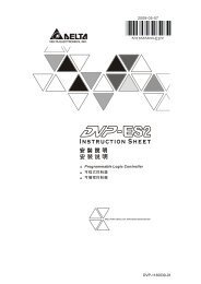
50mmFHU<strong>VFD</strong>-PU01RUN STOP JO G FWD REVJOGRUNSTOPRESET50mm<strong>VFD</strong>-F Series2.2 InstallationCAUTIONThe control, power supply and motor leads must be laid separately. They must not befed through the same cable conduit / trunking.High voltage insulation test equipment must not be used on cables connected to thedrive.Improper installation of the AC drive will greatly reduce its life. Be sure to observe thefollowing precautions when selecting a mounting location.Failure to observe these precautions may void the warranty!• Do not mount the AC drive near heat-radiating elements or in direct sunlight.• Do not install the AC drive in a place subjected to high temperature, high humidity,excessive vibration, corrosive gases or liquids, or airborne dust or metallic particles.• Mount the AC drive vertically and do not restrict the air flow to the heat sink fins.• The AC drive generates heat. Allow sufficient space around the unit for heat dissipation.150mm<strong>VFD</strong>-F150mmAir Flow2-2DELTA ELECTRONICS, INC. ALL RIGHTS RESERVED
<strong>VFD</strong>-F SeriesCHAPTER 3 WIRINGDANGERHazardous VoltageBefore accessing the AC drive:• Disconnect all power to the AC drive.• Wait five minutes for DC bus capacitors discharge.3Any electrical or mechanical modification to this equipment without prior writtenconsent of Delta Electronics, Inc. will void all warranties and may result in a safetyhazard in addition to voiding the UL listing.Short Circuit Withstand:The rated voltage for the AC motor drive must be ≤ 240V for 230V models (≤480V for 460V models) and the mains supply current capacity must be ≤5000A RMS (≤10000A RMS for the ≥ 40hp (30kW) models)DELTA ELECTRONICS, INC. ALL RIGHTS RESERVED 3-1
<strong>VFD</strong>-F Series3.1 Basic Wiring DiagramUsers must connect wires according to the following circuit diagram shown below. Do notplug a Modem or telephone line to the RS-485 communication port, permanent damage mayresult. Pins 1 & 2 are the power sources for the optional copy keypad and should not beused while using RS-485 communication.For 230V series, 1-15 hp models460V series, 1-20hp modelsR/L1S/L2T/L3NFBNFBRecommended Circuitwhen power supplyis turned OFF by afault outputOFFONFactory Setting: SINK ModePlease refer to followingwiring for SINK mode andSOURCE mode.FactorysettingFWD/STOPREV/STOPE.F.Multi-step1Multi-step2Multi-step3Multi-step4RESETJOGAccel/Decel prohibit1/2 Accel/Decel switchSADigital Signal Common*Don't apply the mains voltagedirectly to above terminals.5Kohm 3 214~20mA4~20mAMCSinkSw1SourceDC Reactor(Optional)Jumper+1R/L1S/L2T/L3RB1RC1+2/B1 B2 -U/T1<strong>VFD</strong>-F V/T2W/T3RA1RB1RC1RA2RB2RC2+24VFWDREVEFMI1AFM1MI2AFM2MultifunctionMI3ACMMI4 inputEMI5 terminals RY00 RA3MI6RC3MI7RA4RC4MI8RA5DCMRC5RA6ERC6+10V0-5V 0-10VSw2RA7Power supplyRC7+10V 20mARA8AVIMaster FrequencyRC80~10V/5V(47Kohm) Relay B.D.ACI1 (250ohm) (Optional)(250ohm)ACI2ACM<strong>VFD</strong>B B1PN B2MotorIM3~Multi-function indicationoutput contactsMulti-function Analogoutput terminalFactory setting: output frequency0~10VDC/2mAFactory setting: output currentAnalog Signal CommonRS-485Serial communication interface1: +EV 2: GND 3: SG-4: SG+ 5:NC6: for communicationAnalog Signal CommonMain circuit (power) terminals Control circuit terminals Shielded leads & CableBRBrakeUnit (Optional)BrakeResistor(Optional)Please refer toTerminal Explanation3-2DELTA ELECTRONICS, INC. ALL RIGHTS RESERVED
For 230V series, 20hp and above models460V series, 25hp and above modelsR/L1S/L2T/L3NFBNFBRecommended Circuitwhen power supplyis turned OFF by afault outputOFFMCONFactory Setting: SINK ModePlease refer to followingwiring for SINK mode andSOURCE mode.FactorysettingFWD/STOPREV/STOPE.F.Multi-step1Multi-step2Multi-step3Multi-step4RESETJOGAccel/Decel prohibit1/2 Accel/Decel switchSADigital Signal Common*Don't apply the mains voltagedirectly to above terminals.5Kohm 3 214~20mA4~20mAMCSinkSw1SourceDC Reactor(Optional)Jumper+1 +2 -R/L1S/L2U/T1T/L3 <strong>VFD</strong>-F V/T2W/T3RB1RC1RA1RB1RC1RA2RB2RC2+24VFWDREVEFMI1AFM1AFM2MI2MI3MultifunctionACMMI4 inputEMI5 terminals RY00 RA3RC3MI6RA4MI7RC4MI8RA5RC5DCMRA6ERC60-5V 0-10V+10V Sw2RA7Power supplyRC7+10V 20mARA8AVIMaster FrequencyRC80~10V/5V(47Kohm) Relay B.D.ACI1 (250ohm) (Optional)(250ohm)ACI2ACM<strong>VFD</strong>B B1PN B2BrakeUnit (Optional)BrakeResistor(Optional)MotorIM3~Multi-function indicationoutput contactsPlease refer toTerminal ExplanationMulti-function Analogoutput terminalFactory setting: output frequency0~10VDC/2mAFactory setting: output currentAnalog Signal Common<strong>VFD</strong>-F SeriesRS-485Serial communication interface1: +EV 2: GND 3: SG-4: SG+ 5:NC6: for communicationAnalog Signal CommonMain circuit (power) terminals Control circuit terminals Shielded leads & Cable3DELTA ELECTRONICS, INC. ALL RIGHTS RESERVED 3-3
<strong>VFD</strong>-F SeriesWiring for SINK mode and SOURCE modeJOG1/2 Accel/Decel switchMI7MI8SinkSw1SourceJOG1/2 Accel/Decel switchMI7MI83-4DELTA ELECTRONICS, INC. ALL RIGHTS RESERVED
<strong>VFD</strong>-F Series3.2 Terminal ExplanationsTerminal SymbolExplanation of Terminal FunctionR/L1, S/L2, T/L3 AC line input terminalsU/T1, V/T2, W/T3 AC drive output terminals motor connections+1,+2 Connections for DC Link Reactor (optional)+2/B1~B2 Connections for Brake Resistor (optional)+2~ -,+2/B1~ - Connections for External Brake Unit (<strong>VFD</strong>B series)3Earth Ground3.3 Control Terminals ExplanationsTerminal Symbols Terminal Functions Factory SettingsFWD Forward-Stop commandREV Reverse-Stop commandEFExternal faultMI1 Multi-function Input 1 Factory default: Multi-step speed command 1MI2 Multi-function Input 2 Factory default: Multi-step speed command 2MI3 Multi-function Input 3 Factory default: Multi-step speed command 3MI4 Multi-function Input 4 Factory default: Multi-step speed command 4MI5 Multi-function Input 5 Factory default: RESETMI6 Multi-function Input 6 Factory default: JOGMI7 Multi-function Input 7 Factory default: Accel/Decel prohibitMI8 Multi-function Input 8 Factory default: Accel/Decel time switch 1+24V DC Voltage Source (+24V, 20mA), used for source mode.DCM Digital Signal CommonUsed as common for digital inputs and usedfor sink mode.DELTA ELECTRONICS, INC. ALL RIGHTS RESERVED 3-5
<strong>VFD</strong>-F SeriesTerminal Symbols Terminal Functions Factory SettingsRA 1Multi-function Relay1 output(N.O.) aRB 1Multi-function Relay1 output(N.C.) bRC 1 Multi-function Relay1 common1.5A(N.O.)/1A(N.C.) 240VACRA 2Multi-function Relay2 output1.5A(N.O.)/1A(N.C.) 24VDC(N.O.) aRefer to Pr.03-00 to Pr.03-01RB 2Multi-function Relay2 output(N.C.) bRC 2 Multi-function Relay2 common+10V Potentiometer power source +10V 20mAAVIACI 1/2AFM 1AFM 2ACMAnalog voltage InputAnalog current InputAnalog frequency /currentmeter 1Analog frequency /currentmeter 2Analog control signal(common)0 to +10V correspond to Max.operation frequency4 to 20mA correspond to Max.operation frequency0 to 10V correspond to Max.operation frequency4 to 20mA correspond to 2 times ofoutput current* Control signal wiring size: 18 AWG (0.75 mm 2 ).3-6DELTA ELECTRONICS, INC. ALL RIGHTS RESERVED
<strong>VFD</strong>-F Series3.4 Main Circuit Wiring1HP to 5HP(<strong>VFD</strong>007F23A/43A, <strong>VFD</strong>015F23A/43A, <strong>VFD</strong>022F23A/43A, <strong>VFD</strong>037F23A/43A)3+1 +2 B1 - B2R/L1 S/L2 T/L3U/T1 V/T2 W/T3Screw Torque :18Kgf-cmWire Gauge :18~10AWGControl TerminalTorque: 4Kgf-cm (3 in-lbf)Wire: 12-24 AWGPower TerminalTorque: 18 kgf-cm (15.6 in-lbf)Wire Gauge: 10-18 AWGWire Type: Stranded copper only, 75° CDELTA ELECTRONICS, INC. ALL RIGHTS RESERVED 3-7
<strong>VFD</strong>-F Series7.5 HP to 20 HP(<strong>VFD</strong>055F23A/43B, <strong>VFD</strong>075F23A/43B, <strong>VFD</strong>110F23A/43A, <strong>VFD</strong>150F43A)POWERIM3MOTORControl TerminalTorque: 4Kgf-cm (3 in-lbf)Wire: 12-24 AWGPower TerminalTorque: 30Kgf-cm (26 in-lbf)Wire: 12-8 AWGWire Type: Stranded copper only, 75° CNOTE: If wiring of the terminal utilizes the wire with a 6AWG-diameter, it is thus necessaryto use the Recognized Ring Terminal to conduct a proper wiring.3-8DELTA ELECTRONICS, INC. ALL RIGHTS RESERVED
<strong>VFD</strong>-F Series20 HP to 40 HP(<strong>VFD</strong>150F23A, <strong>VFD</strong>185F23A/43A, <strong>VFD</strong>220F23A/43A, <strong>VFD</strong>300F43A)3R/L1 S/L2 T/L3 +1 +2 -POWER DC ( + ) DC ( -)3 IMV/T2 W/T3MOTORControl TerminalTorque: 4Kgf-cm (3 in-lbf)Wire: 12-24 AWGPower TerminalTorque: 30Kgf-cm (26 in-lbf)Wire: 8-2 AWGWire Type: Stranded copper only, 75° CNOTE: If wiring of the terminal utilizes the wire with a 1AWG-diameter, it is thus necessaryto use the Recognized Ring Terminal to conduct a proper wiring.DELTA ELECTRONICS, INC. ALL RIGHTS RESERVED 3-9
POWERALARM<strong>VFD</strong>-F Series50 HP to 60 HP(<strong>VFD</strong>370F43A, <strong>VFD</strong>450F43A)CHARGER/L1 +1 +2 -S/L2 T/L3 U/T1 V/T2 2/T3IM POWER 3 MOTORControl TerminalTorque: 4Kgf-cm (3 in-lbf)Wire: 12-24 AWGPower TerminalTorque: 57kgf-cm (49.5 in-lbf) min.Wire Gauge: <strong>VFD</strong>370F43A: 3AWG<strong>VFD</strong>450F43A: 2AWGWire Type: Stranded copper only, 75° C3-10DELTA ELECTRONICS, INC. ALL RIGHTS RESERVED
(173in-lbf)POWERALARM<strong>VFD</strong>-F Series40 HP to 125 HP(<strong>VFD</strong>300F23A, <strong>VFD</strong>370F23A, <strong>VFD</strong>550F43A, <strong>VFD</strong>750F43A, <strong>VFD</strong>900F43C)3CHARGER/L1 S/L2 T/L3 +1 +2 U/T1 V/T2 W/T3POWERScrew Torque:200kgf-cmIM3 MOTORControl TerminalTorque: 4Kgf-cm (3 in-lbf)Wire: 12-24 AWGPower TerminalTorque: 200kgf-cm (173 in-lbf)Wire Gauge: <strong>VFD</strong>300F23A, <strong>VFD</strong>550F43A: 1/0-4/0 AWG<strong>VFD</strong>370F23A, <strong>VFD</strong>750F43A: 3/0-4/0 AWG, <strong>VFD</strong>900F43C: 4/0 AWGWire Type: Stranded copper only, 75°CDELTA ELECTRONICS, INC. ALL RIGHTS RESERVED 3-11
<strong>VFD</strong>-F Series125 HP(<strong>VFD</strong>900F43A )R/L1 S/L2 T/L3+1 +2U/T1 V /T2 W/T3POWERMOTORControl TerminalTorque: 4Kgf-cm (3 in-lbf)Wire: 12-24 AWGPower TerminalTorque: 200kgf-cm (173 in-lbf)Wire Gauge: 4/0 AWGWire Type: Stranded copper only, 75°C3-12DELTA ELECTRONICS, INC. ALL RIGHTS RESERVED
<strong>VFD</strong>-F Series150 HP(<strong>VFD</strong>1100F43A)3R/L1 S/L2 T/L3 +1 +2U/T1 V/T2 W/T3POWERMOTORControl TerminalTorque: 4Kgf-cm (3 in-lbf)Wire: 12-24 AWGPower TerminalTorque: 80kgf-cm (69 in-lbf)Wire Gauge: 300 MCMWire Type: Stranded copper only, 75°CNOTE: It needs following additionalterminal when wiring, and add insulationsheath on position where followingfigure shows.DELTA ELECTRONICS, INC. ALL RIGHTS RESERVED 3-13
<strong>VFD</strong>-F Series150 HP to 215 HP(<strong>VFD</strong>1100F43C, <strong>VFD</strong>1320F43A, <strong>VFD</strong>1600F43A)S/L2 R/L1 +2V/T2T/L3 +1 U/T1 W/T3POWER DC(+) 3 MOTORDC(-)IMControl TerminalTorque: 4Kgf-cm (3 in-lbf)Wire: 12-24 AWGNOTE: It needs following additional terminalwhen wiring. The additional terminaldimension should comply with the followingfigure.Power TerminalTorque: 300kgf-cm (260 in-lbf)Wire Gauge: 1/0 AWG*2-300 MCM*2Wire Type: Stranded copper only, 75°CUNIT:mm3-14DELTA ELECTRONICS, INC. ALL RIGHTS RESERVED
<strong>VFD</strong>-F Series250 HP to 300 HP(<strong>VFD</strong>1850F43A, <strong>VFD</strong>2200F43A)3R/L1 S/L2 T/L3 + - U/T1 V/T2 W/T3POWER DC ( + ) DC (-)Control TerminalTorque: 4Kgf-cm (3 in-lbf)Wire: 12-24 AWGNOTE: It needs following additional terminalwhen wiring, and add insulation sheath onposition where following figure shows.Power TerminalTorque: 408kgf-cm (354 in-lbf)Wire Gauge: 500 MCM (max)Wire Type: Stranded copper only, 75°CDELTA ELECTRONICS, INC. ALL RIGHTS RESERVED 3-15
<strong>VFD</strong>-F Series3.5 Wiring Notes: PLEASE READ PRIOR TO INSTALLATION.1. ! CAUTION: Do not connect the AC power to the U/T1, V/T2, W/T3 terminals, as itwill damage the AC drive.2. ! WARNING: Ensure all screws are tightened to the proper torque rating.3. During installation, follow all local electrical, construction, and safety codes for thecountry the drive is to be installed in.4. Ensure that the appropriate protective devices (circuit breaker or fuses) are connectedbetween the power supply and AC drive.5. Make sure that the leads are connected correctly and the AC drive is properly grounded.(Ground resistance should not exceed 0.1Ω.)6. Use ground leads that comply with AWG/MCM standards and keep them as short aspossible.7. Multiple <strong>VFD</strong>-F units can be installed in one location. All the units should be groundeddirectly to a common ground terminal. The <strong>VFD</strong>-F ground terminals may also beconnected in parallel, as shown in the figure below. Ensure there are no ground loops.Forwardrunning8. When the AC drive output terminals U/T1, V/T2, and W/T3 are connected to the motorterminals U/T1, V/T2, and W/T3, respectively, the motor will rotate counterclockwise (asviewed from the shaft ends of the motor) when a forward operation command is received.To reverse the direction of motor rotation, switch over any of the two motor leads.9. Make sure that the power source is capable of supplying the correct voltage andrequired current to the AC drive.10. Do not attach or remove wiring when power is applied to the AC drive.11. Do not inspect components unless inside “CHARGE” lamp is turned off.12. Do not monitor the signals on the circuit board while the AC drive is in operation.3-16DELTA ELECTRONICS, INC. ALL RIGHTS RESERVED
<strong>VFD</strong>-F Series13. For the single-phase rated AC drives, the AC power can be connected to any two of thethree input terminals R/L1, S/L2, T/L3. Note: This drive is not intended for the usewith single-phase motors.14. Route the power and control wires separately, or at 90°angle to each other.15. If a filter is required for reducing EMI (Electro Magnetic Interference), install it as closeas possible to AC drive. EMI can also be reduced by lowering the Carrier Frequency.316. If the AC drive is installed in the place where a load reactor is needed, install the filterclose to U/T1, V/T2, W/T3, side of AC drive. Do not use a Capacitor or L-C Filter(Inductance-Capacitance) or R-C Filter (Resistance-Capacitance), unless approved byDelta.17. When using a GFCI (Ground Fault Circuit Interrupt), select current sensor with sensitivityof 200mA, and not less than 0.1-second detection to avoid nuisance tripping.18. To improve the input power factor, to reduce harmonics and provide protection from ACline disturbances (surges, switching spikes, short interruptions, etc.), AC line reactorshould be installed when the power supply capacity is 500kVA or more.19. There are highly sensitive MOS components on the printed circuit boards. Thesecomponents are especially sensitive to static electricity. To prevent damage to thesecomponents, do not touch these components or the circuit boards with metal objects oryour bare hands.DELTA ELECTRONICS, INC. ALL RIGHTS RESERVED 3-17
<strong>VFD</strong>-F Series3.6 Motor Operation Precautions1. When using the AC drive to operate a standard 3-phase induction motor, notice that theenergy loss is greater than for an inverter duty motor.2. Avoid running a standard induction motor at low speed. Under these conditions, themotor temperature may rise above the motor rating due to limited airflow produced bythe motor’s fan.3. When the standard motor operates at low speed, the output load must be decreased.4. If 100% output torque is desired at low speed, it may be necessary to use a special“inverter-duty” rated motor.3-18DELTA ELECTRONICS, INC. ALL RIGHTS RESERVED
<strong>VFD</strong>-F SeriesCHAPTER 4 DIGITAL KEYPAD OPERATIONThis chapter describes the various controls and indicators found on the digital keypad. Theinformation in this chapter should be read and understood before performing the start–upprocedures described in the chapter of parameter settings. Description of the Keypad Description of Display Keypad Operation Modes & Programming Steps44.1 <strong>VFD</strong>-PU014.1.1 <strong>VFD</strong>-PU01 Dimensions: mm (inch)73.0 [2.87]19.0 [0.75]44.0 [1.73]M4* 0.7(2X)JOGRUNMODEPROGDATASTOP110.0 [4.33]6.5 [0.26]77.0 [3.03]? 40.0[1.58]97.0 [3.82]DELTA ELECTRONICS, INC. ALL RIGHTS RESERVED 4-1
<strong>VFD</strong>-F Series4.1.2 Description of the Digital Keypad <strong>VFD</strong>-PU01FHU<strong>VFD</strong>-PU01LED DisplayDisplay frequency, current, voltageand error, etc.Part NumberJOGBy pressing JOG key.Initiates jog operation.Left keymoves cursor to the leftJOGStatus DisplayDisplay the driver's current statusMODEChanges between differentdisplay mode.UP and DOWN KeySets the parameternumber and changes thenumerical data, such asMaster Frequency.RUNSTOPRESETSTOP/RESETRUN keyDisplay MessageDescriptionsDisplay the AC drive Master Frequency.Display the actual operation frequency present at terminalsU/T1, V/T2, and W/T3.Display voltage (V), Current (A), power factor and feedbacksignal (P)Display the output current present at terminals U/T1, V/T2,and W/T3.Display the AC drive forward run status.4-2DELTA ELECTRONICS, INC. ALL RIGHTS RESERVED
<strong>VFD</strong>-F SeriesDisplay MessageDescriptionsThe AC drive reverse run status.Display the specified parameter setting.Display the actual value stored within the specifiedparameter.External Fault.4Display “End” for approximately 1 second if input has beenaccepted. After a parameter value has been set, the newvalue is automatically stored in memory. To modify an entry,use the or keys.Display “Err”, if the input is invalid.DELTA ELECTRONICS, INC. ALL RIGHTS RESERVED 4-3
<strong>VFD</strong>-F Series4.1.3 Operation steps of the Digital Keypad <strong>VFD</strong>-PU01Selecting modeSTARTFHUMODEFHUMODEFHUMODEFHUMODEFHUMODENote: In the selection mode, pressto set the parameters.GO STARTSetting parametersFHUFHUMODEFHUmove to previous displayFHUSuccess to set parameter.FHUInput data errorNOTE: In the parameter setting mode, you can pressMODEto return the selecting mode.To shift dataFHUSTARTFHUFHUFHUFHUTo modify dataFHUSTARTFHUFHUSetting directionFHUFHUFHUoror4-4DELTA ELECTRONICS, INC. ALL RIGHTS RESERVED
4.2 KPF-CC014.2.1 Description of the Digital Keypad KPF-CC01<strong>VFD</strong>-F SeriesLCD DisplayIndicates frequency, voltage, current, userdefined units, read, and save etc.Model NumberStatus DisplayDisplay the driver'scurrent status.JOG Operation keyPress this key to executethe JOG frequency operation.Left keyMoves the cursor left.UP and DOWN keySet the parameter number andchanges the numerical data, suchas Master Frequency.FWD/REV Direction keySelect FWD/REV operationRUN keyStart AC drive operation.MODEChange between different display mode.Parameter Unit keySwitch the operation command source.Right keyMoves the cursor right.PROG/DATAUsed to enter programming parameters.STOP/RESETStops AC drive operation or reset the driveafter fault occurred.44.2.2 Explanation of Display MessageDisplay MessageDescriptionThe AC motor drive Master Frequency Command.The Actual Operation Frequency present at terminals U, V, W.The output current present at terminals U, V, W.The specified group description.The specified parameter description and settingCopy Mode: Press MODE key for about 2~3 seconds in mainpage. Use UP/DOWN key to select copy function (Read, Write,Delete) and LEFT/RIGHT key to select memory address. Totaltwo blocks are available.DELTA ELECTRONICS, INC. ALL RIGHTS RESERVED 4-5
<strong>VFD</strong>-F SeriesDisplay MessageDescriptionUse UP/DOWN key to confirm copy function. Press PROG/DATAkey to execute.External Fault.Input data is accepted.Input data is invalid.4.2.3 KPF-CC01 Operation Flow ChartKPF-CC01 Operation Flow Chart4-6DELTA ELECTRONICS, INC. ALL RIGHTS RESERVED
<strong>VFD</strong>-F SeriesCHAPTER 5 DESCRIPTION OF PARAMETER SETTINGS: This parameter can be set during operation.5.1 Group 0: AC Drive Status Parameters Group 0 is read-only.00 - 00 Software Version Factory setting: Read Only This parameter displays the software version of AC drive.00 - 01 AC Drive Status Indication 1 Factory setting: Read Only This parameter displays the AC drive status.Code AC Drive Status Explanation00 No fault occurred01 oc over current02 ov over voltage03 oH over temperature04 oL overload05 oL1 electronic thermal relay06 EF (external fault) EF-DCM is closed07 occ (AC drive IGBT fault ) IGBT short circuit protection08 cF3 (CPU failure) Abnormal A/D reading during self-check09 HPF (hardware protection failure) Hardware protection function activatedduring self-check.10 ocA (over current during acceleration) Output current exceeds protection levelduring acceleration11 ocd (over current during deceleration) Output current exceeds protection levelduring deceleration12 ocn (over current during steady stateoperation)Output current exceeds protection levelduring steady state operation.13 GFF (ground fault) Ground fault protection feature activated14 Lv (under voltage) Low input voltage15 cF1 EEPROM input data is abnormal16 cF2 EEPROM output data is abnormal17 bb (base block) BB is set and activated18 oL2 (motor over load 2) Output current exceeds rated motor current19 Reserved20 codE software or password protection21 EF1 (external emergency stop) EF1 (a multifunction-DCM is enabled)22 PHL (phase loss) Input power lacks phase.3-phase input power is unbalance andexceeds specification.23 Lc (Low Current) Low current detection during operation.24 FbL(Feedback Loss) Feedback signal is abnormal.25 Reserved5DELTA ELECTRONICS, INC. ALL RIGHTS RESERVED 5-1
<strong>VFD</strong>-F SeriesCode AC Drive Status Explanation26 FAnP Fan Power Fault27 FF1 Fan 1 Fault28 FF2 Fan 2 Fault29 FF3 Fan 3 Fault30 FF123 Fan 1, 2, 3 Fault31 FF12 Fan 1, 2 Fault32 FF13 Fan 1, 3 Fault33 FF23 Fan 2, 3 Fault34 Fv Gate Drive Low Voltage Protect00 - 02 AC Drive Status Indication 2 Factory setting: Read OnlyDisplay Bit 0~1: 00: Run LED is off and STOP led is on. (AC Drive stopping)01: Run LED is blink and STOP led is on. (AC Drive deceleration to stop)10: Run LED is on and STOP led is blink. (AC Drive standby)11: Run LED is on and STOP led is off. (AC Drive running)Bit 2: 1: Jog on.Bit 3~4: 00: Rev LED is off and FWD led is on. (Forward)01: Rev LED is blink and FWD led is on. (Reverse to Forward)10: Rev LED is on and FWD led is blink. (Forward to Reverse)11: Rev LED is on and FWD led is off. (Reverse)Bit 5-7: ReservedBit 8: Master frequency source via communication interfaceBit 9: Master frequency source via analogBit10: Running command via communication interfaceBit11: Parameter lockedBit12~15: Reserved00 - 03 Frequency Setting Factory setting: Read Only This parameter displays the frequency command set by the user.00 - 04 Output Frequency Factory setting: Read Only This parameter displays actual output frequency of the AC drive.00 - 05 Output Current Factory setting: Read Only This parameter displays actual output current of the AC drive.00 - 06 DC-BUS Voltage Factory setting: Read Only This parameter displays DC-BUS voltage of the AC drive.00 - 07 Output Voltage Factory setting: Read Only This parameter displays output voltage of the AC drive.00 - 08 Output Power Factor Factory setting: Read Only5-2DELTA ELECTRONICS, INC. ALL RIGHTS RESERVED
This parameter displays output power factor.<strong>VFD</strong>-F Series00 - 09 Output Power (kW) Factory setting: Read Only This parameter displays output power of the AC drive.00 - 10 Feedback Signal Actual Value Factory setting: Read Only This parameter displays feedback signal value.00 - 11 Feedback Signal (%) Factory setting: Read Only This parameter displays feedback signal value (%).00 - 12 User Target Value (Low bit) uL 0-99.99 Factory setting: Read Only00 - 13 User Target Value (High bit) uH 0-9999 Factory setting: Read Only User Target Value = Actual output frequency (0-04) × User Defined Multiplier (02-10). Maximum summed display of both parameters is 999999.99.5 When User Target Value
<strong>VFD</strong>-F Series5.2 Group 1: Basic Parameters01 - 00 Maximum Output Frequency Factory Setting: 60.00Settings 50.00~120.00Hz This parameter determines the AC drives maximum output frequency. All master frequencycommands set by the keypad or analog inputs are limited by this parameter. The analogcommands (AVI, ACI1 and ACI2) may be scaled to correspond to the output frequencyrange. (Please refer to 04-09~04-20.)01 - 01 Maximum Voltage Frequency (Base Frequency) Factory Setting: 60.00Settings 0.10~120.00 Hz This parameter sets the frequency, where the maximum output voltage (Pr. 01-02) will bereached. The output frequency may exceed this setting, but the output voltage doesn’tincrease beyond this point. This parameter should be set according to the rated frequencyof the motor as indicated on the motor nameplate. If this parameter setting is smaller than the rated frequency of the motor, nuisance overcurrent faults or damage to the AC drive may occur. If this parameter setting is greater than the rated frequency of the motor, the motor willencounter torque loss.01 - 02 Maximum Output Voltage Factory Setting: 220.0/440.0Settings 230V series: 0.1 ~ 255.0V460V series: 0.2 ~ 510.0V This parameter determines the Maximum Output Voltage of the AC drive. This parametersetting should be set according to rated voltage of the motor as indicated on the motornameplate. If rated voltage of the motor is 440V, this parameter must be set to 440V. If ratedvoltage of the motor is 380V, this parameter must be set to 380V. If this setting is greater than the rated voltage of the motor, nuisance over current faults ordamage to the AC drive may occur.01 - 03 Mid-point Frequency Factory Setting: 1.50Settings 0.10~120.00 Hz This parameter sets the Mid-point Frequency of the V/f curve. This parameter must meet the following argument. Pr.1-01 >= Pr.1-03 >= Pr.1-05.5-4DELTA ELECTRONICS, INC. ALL RIGHTS RESERVED
<strong>VFD</strong>-F Series01 - 04 Mid-point Voltage Factory Setting: 5.5/11.0Settings 230V series: 0.1 ~ 255.0V460V series: 0.2 ~ 510.0V This parameter sets the Mid-point Voltage of the V/f curve. This parameter must meet the following argument. Pr.1-02 >= Pr.1-04 >= Pr.1-06.01 - 05 Minimum Output Frequency Factory Setting: 1.50Settings 0.10~20.00 Hz This parameter sets the Minimum Output Frequency of the AC drive. This parameter mustbe lower than or equal to the Mid-point frequency01 - 06 Minimum Output Voltage Factory Setting: 5.5/11.0Settings 230V series: 0.1 ~ 50.0V460V series: 0.2 ~100.0V This parameter sets the Minimum Output Voltage of the AC Drive. The parameter must belower than or equal to the Mid-point Voltage.501 - 07 Upper Bound Frequency Factory Setting: 60.00Settings 0.00~120.00 Hz This parameter will limit the maximum output frequency of AC drive. If slip compensation(Pr.07-02~07-05) or feedback control (Pr.10-00~10-09) are enabled, the output frequencyof AC drive may exceed the Master Frequency Command, but it will continue to be limitedby this parameter setting.01 - 08 Lower Bound Frequency Factory Setting: 0.00Settings 0.00~120.00 Hz This parameter will limit the minimum output frequency. Any Master Frequency Commandbelow Pr.1-08, will result in an output equal to Pr.1-08. Upon a start command, the drive will accelerate from Pr.1-05 Minimum Output Frequencyto the Master Frequency Command point. The Lower Bound Frequency setting must be smaller than the Dwell Frequency(Pr.11-08>=01-08). If lower bound frequency setting is greater than the Dwell Frequency,the AC drive will equalize the two settings to the Lower Bound point.DELTA ELECTRONICS, INC. ALL RIGHTS RESERVED 5-5
<strong>VFD</strong>-F SeriesOutput voltage01-0201-0401-0601-05 01-08 01-03 01-0101-00 01-07Output Frequency01 - 09 Acceleration Time 1 Factory Setting: 10.0/60.001 - 10 Deceleration Time 1 Factory Setting: 10.0/60.001 - 11 Acceleration Time 2 Factory Setting: 10.0/60.001 - 12 Deceleration Time 2 Factory Setting: 10.0/60.001 - 13 Acceleration Time 3 Factory Setting: 10.0/60.001 - 14 Deceleration Time 3 Factory Setting: 10.0/60.001 - 15 Acceleration Time 4 Factory Setting: 10.0/60.001 - 16 Deceleration Time 4 Factory Setting: 10.0/60.001 - 17 JOG Acceleration Time Factory Setting: 10.0/60.001 - 18 JOG Deceleration Time Factory Setting: 10.0/60.0Settings 0.1~3600.0 Sec Unit: 0.1sec Acceleration time is the time required for the AC drive to ramp from 0 Hz to its MaximumOutput Frequency (Pr.1-00). Deceleration time is the time required for the AC drive todecelerate from Maximum Output Frequency (Pr.1-00) down to 0 Hz. An Acceleration or Deceleration time that is too quick, may cause the AC drives protectionfeatures to enable (over-current stall prevention during Accel 06-01 or over-voltage stallprevention 06-00). If this occurs, the actual Accel/Decel time will be longer than this setting. Warning: An acceleration or deceleration that is too quick, may cause excess loads on theAC drive and may permanently damage the drive. If you want to decelerate the AC drive in short time period, we recommend to add anexternal brake module and brake resistor. You can set 1 st to 4 th Accel/Decel time via multi-function input terminals 04-00 to 04-07.5-6DELTA ELECTRONICS, INC. ALL RIGHTS RESERVED
<strong>VFD</strong>-F Series01 - 19 JOG Frequency Factory Setting: 6.00Settings 0.0 Hz~120.00 Hz Unit: 0.1sec When the JOG function is to be utilized, users need to use the multi-function input terminals(Pr. 04-00 to 04-07 set to 07) or the JOG key on keypad. Once a JOG command is initiated,the AC drive will accelerate from the Minimum Output Frequency (Pr.01-05) to the JOGfrequency (Pr.01-19). The accel/decel time of the JOG operation is determined by the JOG accel/decel speed(Pr.01-17 and 01-18). When the drive is in operation, the JOG command is disabled.01 - 20 S Curve Delay Time in Accel Factory Setting: 0.0001 - 21 S Curve Delay Time in DecelSettings 0.00~2.50sec These parameters enable the S curve. The longer the S curve time period the smoother thetransition between speeds.501 - 22 Modulation Index Factory Setting: 1.00Settings 0.90~1.20 Unit: 0.1 This parameter sets the ratio of the Maximum Output Voltage to the input voltage. The Maximum Output Voltage (Pr.01-02) is normally limited to the input voltage. With theModulation Index parameter, the user is able to increase the output voltage beyond theincoming line voltage. A Modulation Index of 1, defines the Maximum Output Voltage (Pr. 1-02) is equal to theinput voltage. A Modulation index of 1.2, defines the Maximum Output Voltage (Pr. 1-02) is 20% higherthan in the input voltage. Please note, the output voltage wave form will be distorted due toharmonics and may increase torque ripple and noise in the motor.01 - 23 Accel/Decel Time Unit Factory Setting: 01Settings 00: Unit is 1 Sec01: Unit is 0.1 Sec02: Unit is 0.01 Sec This parameter sets the resolution of accel/decel time (Pr.01-09 to 01-18). A high resolution decreases the accel/decel time range as shown in the following chart.DELTA ELECTRONICS, INC. ALL RIGHTS RESERVED 5-7
<strong>VFD</strong>-F Series01-23 Accel/Decel time unit Accel/Decel time range00 1 Sec 1~36000 Sec01 0.1 Sec 0.1~3600.0 Sec02 0.01 Sec 0.01~360.00 Sec5-8DELTA ELECTRONICS, INC. ALL RIGHTS RESERVED
<strong>VFD</strong>-F Series5.3 Group 2: Operation Method Parameters02 - 00 Source of Frequency Command Factory Setting: 00Settings 00: via keypad01: via analog input AVI02: via analog input ACI103: via analog input ACI204: via RS485 serial communication05: via External ReferenceSettings:00: Frequency command source is the keypad. User may use UP/DOWN keys to adjust thefrequency command. Also if the Multi-Function Input terminals (Pr.04-00 to 04-07) areset to 13 or 14, their function will be the same as the UP/DOWN keys.01: Frequency command source is the analog input terminal AVI.02: Frequency command source is the analog input terminal ACI1.03: Frequency command source is the analog input terminal ACI2.04: Frequency command source is the RS485 serial communication.05: Frequency command source depends on the setting of Pr. 04-24. You may use SW2 on the control board to choose between a 0~10V or 0~5V input range.When AVI is set to 0~5V, the voltage input is limited to 5V maximum. The relationship tofrequency is 0V = 0hz and 5V = Pr1-00.502 - 01 Source of Operation Command Factory Setting: 00Settings 00: Controlled by the digital keypad01: Controlled by the external terminals, keypad STOP enabled.02: Controlled by the external terminals, keypad STOP disabled.03: Controlled by the RS-485 communication interface, keypad STOPenabled.04: Controlled by the RS-485 communication interface, keypad STOPdisabled. This parameter sets the operation command source of the AC drive. When the AC drive is controlled by an external source, you may select 2-wire or 3-wireoperation. Please refer to Pr.02-05.DELTA ELECTRONICS, INC. ALL RIGHTS RESERVED 5-9
<strong>VFD</strong>-F Series02 - 02 Stop Method Factory Setting: 00Settings 00:Stop = ramp to stop, E.F. (External Fault) = coast to stop01:Stop = coast to stop, E.F. = coast to stop02:Stop = ramp to stop, E.F. = ramp to stop03:Stop = coast to stop, E.F. = ramp to stop Ramp: The AC drive decelerates the motor to minimum output frequency according to thedeceleration time setting. Coast: The AC drive output instantly stops upon command and the motor free spins until itcomes to a complete stop. External Fault may be enabled by the EF terminal or a Multi-Function terminal. Please referto Pr.04-00 to 04-07. Loss of an ACI signal may cause an E.F condition. Please refer to 02-07.OutputFrequencyMotorspeedFrequencyOutputFrequencyMotorSpeedFrequencyOperationCommandRUNStops accordingto decelerationtimeSTOPTimeFree runningOperationto stopCommand RUN STOPTimeRamp Coast02 - 03 PWM Carrier Frequency Selections Unit: 1Settings 1~10HP 4000~10000Hz Factory Setting: 9000Hz15~30HP 3000~9000HzFactory Setting: 6000Hz≧40HP 2000~6000HzFactory Setting: 4000Hz This parameter sets the carrier frequency of PWM output. The factory setting and settingrange depend on the model type. When the temperature of the heat sink is greater than its limit, the AC drive will automaticlower the carrier frequency to avoid over heating the AC drive.5-10DELTA ELECTRONICS, INC. ALL RIGHTS RESERVED
<strong>VFD</strong>-F Series The Carrier frequency of the PWM output has a signification influence on theelectromagnetic noise, heat dissipation of the AC drive, and the acoustic noise to the motoras shown in the following chart.CarrierfrequencySignificationAcousticNoiseMinimalElectromagneticNoiseLeakageCurrentHeatDissipationSignification Signification SignificationMinimal Signification Minimal Minimal Minimal When the carrier frequency is low, current ripple of the AC drive is large. This may result ina current display value greater than the actual value.02 - 04 Forward/Reverse Enable Factory Setting: 00Settings 00: Forward/Reverse enabled01: Reverse disabled02: Forward disabled This parameter enables the direction of the AC drive.502 - 05 2-wire/3-wire Operation Control Modes Factory Setting: 00Settings 00: 2-wire (#1), FWD/STOP, REV/STOP01: 2-wire (#2), RUN/STOP, REV/FWD02: 3-wire This parameter sets the operation mode when operating by external terminals. Please refer to 02-01.02-05 External Terminal00 (2-wire #1)FWD / STOPREV / STOPFWD/STOPREV/STOPFWD:("OPEN":STOP)("CLOSE":FWD)REV: ("OPEN":STOP)("CLOSE":REV)DCM01 (2-wire #2)RUN / STOPREV / FWDRUN/STOPFWD/REVFWD:("OPEN":STOP)("CLOSE":RUN)REV :("OPEN":FWD)("CLOSE":REV)DCM02 3-wireSTOPRUNFWD ("CLOSE":RUN)EF ("OPEN":STOP)REV ("OPEN":FWD)FWD/REV("CLOSE":REV)DCM<strong>VFD</strong>-FDELTA ELECTRONICS, INC. ALL RIGHTS RESERVED 5-11
<strong>VFD</strong>-F Series02 - 06 Line Start Lockout Factory Setting: 01Settings 00: Disabled01: Enabled When enabled, the AC drive will not start when powered up with a run command applied.The AC drive must see the run command transition from stop to run after power up. WhenLine Start Lockout is disabled (also known as Auto-Start), the AC drive will start whenpowered-up with run commands applied.02 - 07 Loss of ACI Signal Factory Setting: 01Settings 00: Decelerate to 0Hz01: E.F.02: Continue operation by the last frequency command This parameter determines the AC drives response to a loss of the ACI input.02 - 08 Start-up Display Selection Factory Setting: 00Settings Bit0~1: 00 = F LED01 = H LED10 = U LED (special display)11 = Fwd / RevBit2: 0 = Fwd LED / 1 = Rev LEDBit3~5: 000 = 1st 7-step001 = 2nd 7-step010 = 3rd 7-step011 = 4th 7-step100 = 5th 7-stepBit6~7: Reserved This parameter determines the display on keypad after each power up. To program this parameter the user must first generate a Hex value with the informationabove. Then using the Hex to Decimal conversion to find the corresponding Decimal valueand enter it into this parameter. For example, a setting of 21 (decimal 21= hex 010101) will display the “H” and “REV” LEDsand the cursor will stay at the 3rd 7-step display upon power up. When setting to U LED, please refer to 02-09.5-12DELTA ELECTRONICS, INC. ALL RIGHTS RESERVED
<strong>VFD</strong>-F Series02 - 09 Special Display Factory Setting: 00Settings 00: A displays output current of AC drive01: U displays DC-Bus voltage of AC drive02: E displays RMS of output voltage03: P displays feedback signal04: PLC display auto procedure state This parameter chooses the display on the keypad immediately following the “U” userdefined setting. “MODE” key will scroll from “F”, “H”, “U”, (Pr. 02-09), FWD, and back to “F”. Users may also use the “LEFT” key on the digital keypad to switch display content.02 - 10 User Defined Coefficient Factory Setting: 1.00Settings 0.01~160.00 Unit: 0.01 When this parameter is set, the “H “display value = actual output frequency of AC drive x02-10.5 If output frequency of AC drive is 90Hz, set 02-10 to 2.5. When H LED lights, the value onthe display is 225.00.02 - 11 Flying Start Factory Setting: 00Settings 00: Disable01: Enable (DC brake disabled) When the AC drive starts into a running motor (Flying Start), it may cause an over current onthe drive and may damage the motor. Using speed search upon start-up will allow the driveto slowly find the motor speed, smoothly take control of the motor, and bring it to commandspeed. If the Flying Start feature is enabled upon start-up, the DC brake 08-01 will be disabled.02 - 12 Flying Start Frequency Factory Setting: 00Settings 00: Begin search from Master Frequency Command01: Begin search from Maximum Frequency (Pr.01-00)02 - 13 Master Frequency Memory Setting Factory Setting: 01Settings 00: Do not remember the last known frequency01: Remember the last known frequencyDELTA ELECTRONICS, INC. ALL RIGHTS RESERVED 5-13
<strong>VFD</strong>-F Series If this parameter is set to 00: The AC drive will not store the last known master frequencycommand, after power is removed. If this parameter is set to 01: The AC drive will memorize the last known master frequencycommand after power off. Upon power up the last known frequency is displayed. After a fault, the AC drive will always remember the last know master frequency command. This feature is only enabled when Pr. 02-00 is set for 0 or 4.5-14DELTA ELECTRONICS, INC. ALL RIGHTS RESERVED
<strong>VFD</strong>-F Series5.4 Group 3: Output Function Parameters03 - 00 Multi-function Output terminal 1 Factory Setting: 0003 - 01 Multi-function Output terminal 2 Factory Setting: 0003 - 02 Multi-function Output terminal 3 Factory Setting: 0003 - 03 Multi-function Output terminal 4 Factory Setting: 0003 - 04 Multi-function Output terminal 5 Factory Setting: 0003 - 05 Multi-function Output terminal 6 Factory Setting: 0003 - 06 Multi-function Output terminal 7 Factory Setting: 0003 - 07 Multi-function Output terminal 8 Factory Setting: 00Settings 00-33Setting FunctionsDescriptions00 No function01 Motor No. 102 Motor No. 203 Motor No. 304 Motor No. 4When starting circulative control, AC drive will05 Motor No. 5automatic set this parameter by 11-01 to 11-03.06 Motor No. 607 Motor No. 708 Motor No. 809 Auxiliary 1 output10 Auxiliary 2 outputParameter value 09 to 15 program11 Auxiliary 3 outputMulti-Function Output Terminals12 Auxiliary 4 output(Pr.03-00~Pr.03-07) to correspond with the AC13 Auxiliary 5 outputdrive multi-function input terminals, Pr.04-00 to04-07(settings 20~26).14 Auxiliary 6 output15 Auxiliary 7 output16 Indication during operation The corresponding output will be closed duringoperation (including DC brake time).17 Master frequencyattainedThe corresponding output will be closed whenoutput frequency reaches master frequencycommand.18 Zero Speed (including shutdown) The corresponding output will be closed whenthe AC drive has no output voltage signal.19 Over-torque The corresponding output relay will be closedwhen the AC drives output current exceeds theover-torque detection level 06-04.20 External Fault The corresponding output will be closed whenthe EF is enabled. (Pr. 4-00 to 4-07)5DELTA ELECTRONICS, INC. ALL RIGHTS RESERVED 5-15
<strong>VFD</strong>-F SeriesSetting FunctionsDescriptions21 Low voltage detection The corresponding output will be closed whenthe DC Bus voltage drops below our threshold.The keypad will display “Lu”.22 Operation Mode indication The corresponding output will be closed whenthe AC drives “Operation Command” iscontrolled by the external terminals.23 Fault Indication The corresponding output will be closed whenAC drive has experienced a fault.24 Master Frequency Attained 1 The corresponding output will be closed whenthe AC drives output frequency exceeds(Pr.03-08) Master Frequency Attained 1.25 Master Frequency Attained 2 The corresponding output will be closed whenthe AC drives output frequency exceeds(Pr.03-09) Master Frequency Attained 2.26 Over Temperature indication The corresponding output will be closed whenthe AC drive temperature exceeds its rating.27 Drive Ready The corresponding output will be closed thewhen the AC drive is ready and has no faults.28 External Emergency Stop (EF1) The corresponding output will be closed whenmulti-function input terminals (Pr.04-00 to04-07) are set to emergency stop and thenactivated.29 Software brake output The corresponding output will be closed whenthe AC drives DC bus voltage exceeds(Pr.08-19) the brake level.30 OL or OL1 overload warning The corresponding output will be closed uponan overload (OL or OL1) fault.31 Dwell indication (sleep) The corresponding output will be closed whenthe AC drive is in a Dwell status (Pr.11-07).32 Low current indication The corresponding output will be closed whenthe AC drives output current is lower than theLow Current setting (Pr.06-08).33 PID feedback error indication The corresponding output will be closed whenthe PID feedback signal has an error.34 PLC Program RunningThe Output will be activated when PLCProgram is running.35 PLC Program Step CompletedThe Output will be activated for 0.5 sec wheneach multi-step speed is attained.36 PLC Program CompletedThe output will be activated for 0.5 sec whenthe PLC program cycle has completedThe output will be activated when PLC37 PLC Operation Pausedoperation is paused. The <strong>VFD</strong>-F has two form C relays (multi-function output 1 and 2). There is an optionalExternal Relay Card with 6 NO contact relays (multi-function outputs 3-8).5-16DELTA ELECTRONICS, INC. ALL RIGHTS RESERVED
External relay specifications = 8A/250VAC or 5A/30VDC.<strong>VFD</strong>-F Series Relay delay time is 5~10 msec.03 - 08 Master Frequency Attained 1 Factory Setting: 0.0003 - 09 Master Frequency Attained 2Settings 0.00~120.00 Hz Unit: 0.01 An output relay may be programmed to activate when the output frequency exceeds thedesired attained frequency setting of these two parameters. There is a ± 2Hz window of operation. If the master frequency attained is 20Hz and theoutput frequency exceeds 20Hz, the corresponding output relay will be “closed”. When theoutput frequency is less than 18Hz, the corresponding output relay will be “opened” as thefollowing diagram shows.Master frequency2 attainedMaster frequency1 attainedMaster frequencyattainedFrequency2Hz2Hz2Hz4HzMasterfrequency 1FrequencycommandMasterfrequency 2TimeOutput frequency503 - 10 Analog Output 1, (AFM1) 0~10Vdc Factory Setting: 0003 - 11 Analog Output 2, (AFM2) 0/4~ 20mA Factory Setting: 01Settings 00: Output frequency01: Output current02: Output voltage03: Frequency command04: Power factor loading These parameters select the content of the analog output signals AFM1 and AFM2. Setting 00: 0-10V = 0 - (Pr.01-00) Setting 01: 0-10V = 0 - (2.52.0 x rated current) Setting 02: 0-10V = 0 - (Pr.01-02) Setting 03: 0-10V = 0 - Master Freq. commandDELTA ELECTRONICS, INC. ALL RIGHTS RESERVED 5-17
<strong>VFD</strong>-F Series Setting 04: 0-10V = 0.0 - output power factor 1.0 When using 0-20mA output, please refer to Pr. 3-14. Maximum impedance loading of analog output 2 (AFM2) can’t be greater than 500 ohms.03 - 12 Analog Output Gain 1 Factory Setting: 10003 - 13 Analog Output Gain 2 Factory Setting: 100Settings 01~200% This parameter is to determine analog output gain. The analog output is limited to 10V and 20mA. The gain is designed to offer a normallysmall output signal to be enlarged for easier viewing on a meter.03 - 14 Analog Output 2 Selection Factory Setting: 01Settings 00: 0~20mA01: 4~20mA This parameter selects the output range of Analog Output 2 (AFM2).03 - 15 DC Fan Control Factory Setting: 00Settings 00: Fan runs on power up.01: Fan begins upon a RUN command. Fan stops 1 minute after aSTOP command.02: Fan begins upon a RUN command. Fan stops after a STOPcommand03: Fan is controlled by temperature. Approximately a 60°Ctemperature will start the fan. This parameter determines DC fan control method.5-18DELTA ELECTRONICS, INC. ALL RIGHTS RESERVED
5.5 Group 4: Input Function Parameters<strong>VFD</strong>-F Series04 - 00 Multi-function Input terminal 1 Factory Setting: 0104 - 01 Multi-function Input terminal 2 Factory Setting: 0204 - 02 Multi-function Input terminal 3 Factory Setting: 0304 - 03 Multi-function Input terminal 4 Factory Setting: 0404 - 04 Multi-function Input terminal 5 Factory Setting: 0504 - 05 Multi-function Input terminal 6 Factory Setting: 0704 - 06 Multi-function Input terminal 7 Factory Setting: 0804 - 07 Multi-function Input terminal 8 Factory Setting: 09Settings 00~31Setting Functions Descriptions00 No function01 Multi-Speed terminal 102 Multi-Speed terminal 203 Multi-Speed terminal 304 Multi-Speed terminal 405 Reset (NO)06 Reset (NC)07 Jog operation (JOG)08 Accel/Decel disable09 Accel/Decel 2 selection10 Accel/Decel 3 selection11 B.B. (NO) input12 B.B. (NC) input13 Increase Frequency14 Decrease Frequency15 Emergency stop (NO)16 Emergency stop (NC)DELTA ELECTRONICS, INC. ALL RIGHTS RESERVED 5-19All unused terminals should be set to 00, toassure they have no effect on drive operation.Allows selection of the 15 multi-step speeds.Please refer to 05-00 to 05-14 to program the15 step speeds.Clears (Reset) a fault and returns the AC driveto normal operation.Enables the JOG command. Works identicalto the JOG key on the digital keypad.Stops the acceleration or deceleration of theAC drive. AC drive then maintains a constantspeed.A corresponding terminal set to value 09 andclosed selects Accel/Decel time 2. Acorresponding terminal set to value 10 andclosed selects Accel/Decel time 3.Accel/Decel time 4 is selected when bothterminals are closed.Enables the base block (pause) function.Please refer to Pr.08-08, for base blockfunctions.Enables the external terminals to increase ordecrease the Master Frequency commandeach time an input is received. Terminals arenot active during a stop command.Generates an external fault (EF1). Thefunction is identical to the external terminal(EF).5
<strong>VFD</strong>-F SeriesSetting Functions Descriptions17 AVI(open), ACI1(close)18 KEYPAD(open), EXT(close)19 PID disable20 Auxiliary 1 input21 Auxiliary 2 input22 Auxiliary 3 input23 Auxiliary 4 input24 Auxiliary 5 input25 Auxiliary 6 input26 Auxiliary 7 input27 Motor No.1 output disable28 Motor No.2 output disable29 Motor No.3 output disable30 Motor No.4 output disable31 All motor outputs disable32 Run PLC Program33 Pause PLC ProgramExternal selection of the Master Frequencycommand. (Analog input AVI = terminal open)or (ACI1 = terminal closed). This settingover-rides Pr.02-00.External selection of the Operation CommandSource. (Keypad = terminal open) or (Externalterminals = terminal closed). This setting isvalid when Pr.02-01 is set to 00. Otherwise, theOperation Command Source will follow thesetting in Pr.02-01.Disable PID feedback control and operate viaMaster Frequency Command source Pr.02-00.Parameter value 20 to 26 programMulti-Function Input Terminals(Pr.04-00~Pr.04-07) to correspond with the ACdrive multi-function output terminals Pr.03-00to 03-07 (settings 09-15).When multiple motors are controlled by an ACdrive, these settings will allow thecorresponding motor to disable and ignore thismotor. AC drive will not accept a “Motor OutputDisabled” signal when it is running.When multiplex motors are in circulativecontrol mode, this terminal can stop the motorthat power supply is not from AC drive and setthe circulative control mode disable. Now onlythe motor in running keeps running.Parameter value 32 programs Multi-FunctionInput Terminal to enable the AC drive internalPLC program. Parameter value 33 programsan input terminal to pause the PLC program.Note: Pr.05-00 to Pr.05-16 defines the PLCprogram.04 - 08 Digital Input Terminal Response Time Factory Setting: 01Settings 01~20 This parameter selects the response time of digital input terminals MI1 to MI8, EF, REV andFWD. AC drive will scan the digital input terminals once every 2msec. During each scan the drivewill check the status of each terminal (open or closed).5-20DELTA ELECTRONICS, INC. ALL RIGHTS RESERVED
<strong>VFD</strong>-F Series In noisy environments, it would be advantageous to verify the terminal status several timesbefore executing a new command, nearly eliminating false signals. Example: If Pr.04-08 is set to 4, the AC drive will confirm the terminal status (4+1 = 5) 5times before a change is made. This correlates to an 8~10msec time response from inputcommand to execution. It is not recommended to set this parameter to 00, since interference may cause improperoperation of the AC drive.04 - 09 AVI Minimum Voltage Factory Setting: 0.004 - 10 AVI Maximum Voltage Factory Setting: 10.0Settings 0.0 ~ 10.0V Unit: 0.104 - 11 AVI Minimum Frequency (percentage of Pr.1-00) Factory Setting: 0.0004 - 12 AVI Maximum Frequency (percentage of Pr.1-00) Factory Setting: 100.00Settings 0.00~100.00% Unit: 0.01504 - 13 ACI1 Minimum Current Factory Setting: 4.004 - 14 ACI1 Maximum Current Factory Setting: 20.0Settings 0.0 ~ 20.0mA Unit: 0.104 - 15 ACI1 Minimum Frequency (percentage of Pr.1-00) Factory Setting: 0.0004 - 16 ACI1 Maximum Frequency (percentage of Pr.1-00) Factory Setting: 100.00Settings 0.0~100.0% Unit: 0.0104 - 17 ACI2 Minimum Current Factory Setting: 4.004 - 18 ACI2 Maximum Current Factory Setting: 20.0Settings 0.0 ~ 20.0mA Unit: 0.104 - 19 ACI2 Minimum frequency (percentage of Pr.1-00) Factory Setting: 0.0004 - 20 ACI2 Maximum frequency (percentage of Pr.1-00) Factory Setting: 100.00Settings 0.00~100.00% Unit: 0.01 The above parameters are used to set the analog input reference values. The min and maxfrequencies are based on Pr.01-00 (during open-loop control) or the PID reference valuePr.10-01 (during PID close-loop control).DELTA ELECTRONICS, INC. ALL RIGHTS RESERVED 5-21
<strong>VFD</strong>-F SeriesPlease refer to the following diagram for more details:01-00, 10-1004-1204-1604-1104-1504-1904-0904-1304-1704-1004-1404-18Analoginput Example: Using the AVI(0~10V) as the target source and ACI1(4~20mA corresponds to0~5Pa) and ACI2(0~10mA corresponds to 0~4Pa) as the feedback location for a pressuresensor connected. If your target value is between 3~7Pa (Set Pr.10-01 to 10, otherparameters settings refer Pr.10-01 to set as shown in the following diagram and then settingthe PID feedback relative parameters.) If setting AVI to 7.5V, pressure sum of ACI1 andACI2 could be controlled at 6Pa.Pressure Pa10-10=10.0 Pa04-12=7004-16=5004-20=40AVIACI204-11=3004-15=004-19=004-9=0V 04-13=4mA04-17=0mAACI104-18=10mAAnaloginput04 - 21 Analog Input Delay AVI Factory Setting: 0.5004 - 22 Analog Input Delay ACI1 Factory Setting: 0.5004 - 23 Analog Input Delay ACI2 Factory Setting: 0.50Settings 0.00 ~ 10.00 Sec Unit: 0.015-22DELTA ELECTRONICS, INC. ALL RIGHTS RESERVED
<strong>VFD</strong>-F Series This parameter selects the time constant for the analog input signal filter. A properlyadjusted time constant may help filter noise on the analog input terminals. If the input delay is set too long, the system may experience oscillation. Be careful settingthese parameters.04 - 24 Summation of External Frequency Sources Factory Setting: 00Settings 00: No functions01: AVI+ACI102: ACI1+ACI203: ACI2+AVI04: Communication master frequency +AVI05: Communication master frequency +ACI106: Communication master frequency +ACI2 This parameter selects the terminals used for summation of the External FrequencySources.5DELTA ELECTRONICS, INC. ALL RIGHTS RESERVED 5-23
<strong>VFD</strong>-F Series5.6 Group 5: Multi-step Speed Frequency Parameters05 - 00 1 st Step Speed Frequency Factory Setting: 0.0005 - 01 2nd Step Speed Frequency Factory Setting: 0.0005 - 02 3rd Step Speed Frequency Factory Setting: 0.0005 - 03 4th Step Speed Frequency Factory Setting: 0.0005 - 04 5th Step Speed Frequency Factory Setting: 0.0005 - 05 6th Step Speed Frequency Factory Setting: 0.0005 - 06 7th Step Speed Frequency Factory Setting: 0.0005 - 07 8th Step Speed Frequency Factory Setting: 0.0005 - 08 9th Step Speed Frequency Factory Setting: 0.0005 - 09 10th Step Speed Frequency Factory Setting: 0.0005 - 10 11th Step Speed Frequency Factory Setting: 0.0005 - 11 12th Step Speed Frequency Factory Setting: 0.0005 - 12 13th Step Speed Frequency Factory Setting: 0.0005 - 13 14th Step Speed Frequency Factory Setting: 0.0005 - 14 15th Step Speed Frequency Factory Setting: 0.00Settings 0.00~120.00 Hz Unit: 0.01 The Multi-Function Input Terminals (refer to Pr.04-00 to 04-07) are used to select one of theAC drive Multi-Step speeds. The speeds (frequencies) are determined by Pr.05-00 to05-14 shown above.05 - 15 PLC Mode Factory Setting: 00Settings 00 Disable PLC operation01 Execute one program cycle02 Continuously execute program cycles03 Execute one program cycle step by step04 Continuously execute program cycles step by step This parameter selects the mode of PLC operation for the AC drive. The AC drive willchange speeds and directions according to the user’s desired programming.5-24DELTA ELECTRONICS, INC. ALL RIGHTS RESERVED
<strong>VFD</strong>-F SeriesExample 1 (Pr.05-15 = 1): Execute one cycle of the PLC program. Its relative parametersettings are:Pr.05-00 to 05-14: 1 st to 15 th step speed (sets the frequency of each step speed)Pr.04-00 to 04-07:Pr.03-00 to 03-07:Pr.05-16:Pr.05-17 to 05-31:Multi-Function Input Terminals (set one multi-function terminal as 32- PLC auto-operation).Multi-Function Output Terminals (set a Multi-Function Terminal as34-PLC running indication, 35-PLC step completed or 36-PLCprogram completed).Direction of operation for the 1 st to 15 th step speed.Operation time setting of the 1 st to 15 th step speed.5Program operationcommandProgram operationindicationStep operationindicationProgram operationfulfillment indicationNote: The above diagram shows one complete PLC cycle. To restart the cycle, turn the PLCprogram off and on again.Example 2 (Pr.05-15 = 2): Continuously executes program cycles:The diagram above shows the PLC program stepping through each speed. Set Pr.05-15 to 2continuously executes the program. To stop the PLC program, one must either pause theprogram or turn it off. (Refer to Pr.04-00 to 04-07 values 32 and 33).DELTA ELECTRONICS, INC. ALL RIGHTS RESERVED 5-25
<strong>VFD</strong>-F SeriesExample 3 (Pr.05-15 = 3) Execute one cycle step by step:The example below shows how the PLC can perform one cycle at a time, within in a completecycle. Each step will use the accel/decel times in Pr.01-09 to Pr.01-16. It should be noticed thatthe time each step spends at its intended frequency is diminished, due to the time spent duringaccel/decel.FrequencyPLC operation execution one cycle step by step05-0205-0305-01Program operationcommand OFFProgram operationindication OFF05-001 2 3 405-17 t05-18 t05-19 t05-20ONON ON ON ONTimeStep operationindication OFF05 - 16 PLC Forward/Reverse Motion Factory Setting: 00Settings 00 to 32767 This parameter controls the direction of motion for the Multi-Step Speeds Pr.05-00 toPr.05-14 during PLC mode. All other direction commands are invalid during the PLC mode.Note:The equivalent 15-bit number is used to program the forward/reverse motion for each ofthe 15 speed steps. The binary notation for the 15-bit number must be translated intodecimal notation and then entered.5-26DELTA ELECTRONICS, INC. ALL RIGHTS RESERVED
<strong>VFD</strong>-F SeriesWeightsBit 15 14 13 12 11 10 9 8 7 6 5 4 3 2 1 0WeightsBit 0 1 0 0 1 1 0 0 0 1 1 1 0 0 1 00=Forward1=ReverseDirection of 1st speed for Pr.05-00Direction of 2nd speed for Pr.05-01Direction of 3rd speed for Pr.05-02Direction of 4th speed for Pr.05-03Direction of 5th speed for Pr.05-04Direction of 6th speed for Pr.05-05Direction of 7th speed for Pr.05-06Direction of 8th speed for Pr.05-07Direction of 9th speed for Pr.05-08Direction of 10th speed for Pr.05-09Direction of 11th speed for Pr.05-10Direction of 12th speed for Pr.05-11Direction of 13th speed for Pr.05-12Direction of 14th speed for Pr.05-13Direction of 15th speed for Pr.05-140=Forward1=ReverseDirection of Pr.05-00, 1st speed = ForwardDirection of Pr.05-01,2nd speed=ReverseDirection of Pr.05-02,3rd speed=ForwardDirection of Pr.05-03,4th speed=ForwardDirection of Pr.05-04,5th speed=ReverseDirection of Pr.05-05,6th speed=ReverseDirection of Pr.05-06,7th speed=ReverseDirection of Pr.05-07,8th speed=ForwardDirection of Pr.05-08,9th speed=ForwardDirection of Pr.05-09,10th speed=ForwardDirection of Pr.05-10,11th speed=ReverseDirection of Pr.05-11,12th speed=ReverseDirection of Pr.05-12, 13th speed=ForwardDirection of Pr.05-13,14th speed=Forward5Direction of Pr.05-14,15th speed=Reverse1413 2 1 0The setting value = bit14x2 + bit13x2 +....+bit2x2 +bit1x2 +bit0x214 11 10 6 5 4 1= 1x2 + 1x2 +1x2 +1x2 +1x2 +1x2 +1x2=16384+2048+1024+64+32+16+2=19570Setting 05-16 =19570NOTE:14131211102 =16384 2 =8192 2 =4096 2 =2048 2 =102492=51242=1682=25632=872=12822=462=6412=252=3202=1DELTA ELECTRONICS, INC. ALL RIGHTS RESERVED 5-27
<strong>VFD</strong>-F Series05 - 17 Time Duration of 1st Step Speed Factory Setting: 0.005 - 18 Time Duration of 2nd Step Speed Factory Setting: 0.005 - 19 Time Duration of 3rd Step Speed Factory Setting: 0.005 - 10 Time Duration of 4th Step Speed Factory Setting: 0.005 - 21 Time Duration of 5th Step Speed Factory Setting: 0.005 - 22 Time Duration of 6th Step Speed Factory Setting: 0.005 - 23 Time Duration of 7th Step Speed Factory Setting: 0.005 - 24 Time Duration of 8th Step Speed Factory Setting: 0.005 - 25 Time Duration of 9th Step Speed Factory Setting: 0.005 - 26 Time Duration of 10th Step Speed Factory Setting: 0.005 - 27 Time Duration of 11th Step Speed Factory Setting: 0.005 - 28 Time Duration of 12th Step Speed Factory Setting: 0.005 - 29 Time Duration of 13th Step Speed Factory Setting: 0.005 - 30 Time Duration of 14th Step Speed Factory Setting: 0.005 - 31 Time Duration of 15th Step Speed Factory Setting: 0.0Settings 0.0 to 65500 Unit: 1 /0.1sec Pr.05-17 to Pr.05-31 correspond to operation time of each step speed defined by Pr.05-00to Pr.05-14. The maximum setting 65500 seconds will be displayed as t6550. If it isdisplayed t6550. that means 6550 seconds.Note: If a parameter is set to “00” (0 sec), the corresponding step will be skipped. This iscommonly used to reduce the number of program steps.5-28DELTA ELECTRONICS, INC. ALL RIGHTS RESERVED
<strong>VFD</strong>-F SeriesFrequency05-0705-0605-0805-0505-0905-0405-1005-0305-1105-0205-1205-01JOG Freq.05-13 01-1905-0005-14Master SpeedRun Signal1st step speed Multi-function TerminalPr.04-00 to Pr.04-07 (MI1 to MI8 1)2nd step speed Multi-function TerminalPr.04-00 to Pr.04-07 (MI1 to MI8 2)3rd step speed Multi-function TerminalPr.04-00 to Pr.04-07 (MI1 to MI8 3)4th step speed Multi-function TerminalPr.04-00 to Pr.04-07 (MI1 to MI8 4)OFFONOFFOFFOFF2 3 4 5 6 7 8 9 101112131415ONON ON ON ON ON ON ONONONON ON ONON5OFFONJog Freq.Multi-Step Speed via External Terminals05 - 32 Time Unit Settings Factory Setting: 00Settings 00 1 Sec01 0.1 Sec This parameter determines the time unit for Pr.05-17~Pr.05-31.DELTA ELECTRONICS, INC. ALL RIGHTS RESERVED 5-29
<strong>VFD</strong>-F Series5.7 Group 6: Protection Function Parameters06 - 00 Over-voltage Stall Prevention Factory Setting: 390.0/780.0Settings 230V series: 330.0 ~ 410.0VDC460V series: 660.0 ~820.0VDC00: Disable This parameter selects the voltage level for the Over-Voltage Stall Prevention function. During decelerations, the DC bus voltage may exceed its maximum allowable value due tomotor regeneration. When this function is enabled, the AC drive will stop decelerating andmaintain a constant output frequency. The AC drive will only resume deceleration when thevoltage drops below the preset value. With moderate inertial loads, the over-voltage stall prevention will not occur and thedeceleration time should be equal to Pr.1-10. With high inertial loads, the AC drive willautomatically extend the deceleration time due to the step function shown below. If thedeceleration time is critical for the application, then dynamic brake resistors should beused.Output frequencyDeceleration characteristicwhen Over-voltage stallprevention enabledFrequency heldTimeDeceleration Time06 - 01 Over-current Stall Prevention during Acceleration Factory Setting: 120Settings 20~150% Unit: 1 This parameter selects the percentage of allowable over-current during acceleration beforethe stall prevention is enabled. During acceleration, the AC drive output current may increase abruptly and exceed thevalue specified by Pr.06-01 due to rapid acceleration or excessive load on the motor. Whenthis function is enabled, the AC drive will stop accelerating and maintain a constant outputfrequency. The AC drive will only resume acceleration when the current drops below thevalue set in Pr.06-01 (please see the graph below). When the over-current stall prevention is activated, the acceleration time of the AC drive willbe longer than the time set in Pr. 01-09.5-30 DELTA ELECTRONICS, INC. ALL RIGHTS RESERVED
<strong>VFD</strong>-F SeriesOver-current StallPrevention duringacceleration06-01CurrentOver-current stallprevention duringacceleration,frequency heldOutputfrequencyTimeOver-current Stall Prevention during Acceleration06 - 02 Over-current Stall Prevention during operation Factory Setting: 120Settings 20~150% Unit: 1 This parameter selects the percentage of allowable over-current during operation beforethe stall prevention function is enabled.5 If the output current exceeds the value specified in Pr.06-02 when the drive is operating atsteady state speed, the drive will decrease its output frequency to prevent the drive fromfaulting with an OC. Once the current falls below the value specified in Pr.06-02, the drivewill then accelerate to catch up with the command frequency.Over-current StallPrevention duringoperation 06-02CurrentOver-current StallPrevention duringoperation, outputfrequency decreaseOutputfrequencyDELTA ELECTRONICS, INC. ALL RIGHTS RESERVED 5-31Over-current Stall Prevention during Operation06 - 03 Over-torque Detection Selection Factory Setting: 00Settings 00: Over-torque detection disabled.01: Over-torque detection enabled during constant speed operation(OL2), and operation continues.02: Over-torque detection enabled during constant speed operation(OL2), and operation halted.03: Over-torque detection enabled during operation (OL2), andoperation continues.04: Over-torque detection enabled during constant speed operation(OL2), and operation halted.Time
<strong>VFD</strong>-F Series This parameter selects the Over-torque Detection operation. If this parameter is set to 01 or 02, over-torque detection will not occur during acceleration.06 - 04 Over-torque Detection Level Factory Setting: 110Settings 30~150% Unit: 1 This parameter sets the Over-torque Detection level based on the AC drive rated current.06 - 05 Over-torque Detection Time Factory Setting: 0.1Settings 0.1~60.0 Sec Unit: 0.1 This parameter selects the allowable time of Over-torque Detection before the AC drivefaults with an OL2. When the output current exceeds Pr.06-04 for the time set in Pr06-05, AC drive will faultand display “OL2” on the keypad.06 - 06 Electronic Thermal Relay Selection Factory Setting: 02Settings 00: Operation disabled.01: Operation with a standard motor (shaft mounted fan cooled).02: Operation with a vector motor (non-fan cooled or self powered fan) This parameter provides electronic thermal protection for the motor. When the outputcurrent exceeds Pr.07-02 for the time set in Pr.06-07, the drive will fault with an OL1.06 - 07 Electronic Thermal Characteristic Factory Setting: 60Settings 30~600 Sec Unit: 1 This parameter selects the time required for the electronic thermal protection function toactivate. When Pr.6-06 is set for 1 or 2 and the output current exceeds Pr.7-02 for the time set inPr.6-07, the drive will fault with an OL1. The common electronic thermal reaction time (150% output current for 1 minute) is shownin the chart below. The actual reaction time will vary depending on output current.5-32DELTA ELECTRONICS, INC. ALL RIGHTS RESERVED
<strong>VFD</strong>-F Series54OperationTime(min)60Hz or more50Hz3210Hz5Hz1Loadfactor(%)0 20 40 60 80 100 120 140 160 180 20006 - 08 Low Current Detection Level Factory Setting: 00Settings 00~100% (00 disabled) Unit: 106 - 09 Low Current Detection Time Factory Setting: 10.0Settings 0.1~ 3600.0 Sec Unit: 0.106 - 10 Low Current Detection Treatment Factory Setting: 01Settings 00: Warn and Ramp to stop01: Warn and Coast to stop02: Warn and keep operating These parameters set the low current detection mode, time, and operation.506 - 11 Present Fault Record Factory Setting: 0006 - 12 Second Most Recent Fault Record Factory Setting: 0006 - 13 Third Most Recent Fault Record Factory Setting: 0006 - 14 Fourth Recent Fault Record Factory Setting: 00Settings 00 No fault occurred01 Over-current (oc)02 Over-voltage (ov)03 Overheat (oH)04 Overload (oL)05 Electronic thermal relay (oL1)06 External fault (EF)07 AC drive IGBT fault (occ)08 CPU failure (cF3)09 Hardware protection failure (HPF)DELTA ELECTRONICS, INC. ALL RIGHTS RESERVED 5-33
<strong>VFD</strong>-F Series10 Over current during acceleration (ocA)11 Over current during deceleration (ocd)12 Over current during steady state operation (ocn)13 Ground fault (GFF)14 Under voltage (Lv)15 EEPROM WRITE failure (cF1)16 EEPROM READ failure (cF2)17 Base Block (bb)18 Motor over load (oL2)19 Reserved20 Software/password protection (codE)21 External emergency stop (EF1)22 Phase-Loss (PHL)23 Low-current (Lc)24 FbL (Feedback Loss)25 Reserved26 Fan Power Fault (FAnP)27 Fan 1 Fault (FF1)28 Fan 2 Fault (FF2)29 Fan 3 Fault (FF3)30 Fan 1, 2, 3 Fault (FF123)31 Fan 1, 2 Fault (FF12)32 Fan 1, 3 Fault (FF13)33 Fan 2, 3 Fault (FF23)34 Gate Drive Low Voltage Protect (Fv)06 - 15 Parameter Reset Factory Setting: 00Settings 00~6553509: Reset parameters (50Hz, 220/380)10: Reset parameters (60Hz, 220/440) This parameter resets all parameters to the factory setting.06 - 16 Parameter Protection Password Input Factory Setting: 00Settings 00~655355-34DELTA ELECTRONICS, INC. ALL RIGHTS RESERVED
<strong>VFD</strong>-F Series This parameter allows the user to enter their password to unlock the Parameter Protectionfeature. The password entered must match the value entered into Pr.6-17. After threeinvalid password attempts, the drive will no longer allow any operation. The drive must thenbe powered off and back on again. After successfully entering the password, the user may change parameters as they wish.Once the drive is powered off, the drive has locked the parameters again. To clear thepassword, the user must enter the correct password in Pr.6-16 and then set Pr.6-17 to 00.06 - 17 Parameter Protection Password Setting Factory Setting: 00Settings 00~6553500: No password protection This parameter allows the user to set a password for parameter protection. After entering apassword, Pr.6-17 will display 1.5 Be sure to keep the password in a safe place. If the password is lost, please return thedrive to DELTA.DELTA ELECTRONICS, INC. ALL RIGHTS RESERVED 5-35
<strong>VFD</strong>-F Series5.8 Group 7: AC Drive and Motor Parameters07 - 00 Identity Code of AC Drive Factory Setting: ##Settings Display by model type This parameter displays the AC drive model code. This parameter is read-only.07 - 01 Rated Current of AC Drive Factory Setting: ##Settings Display by model type This parameter displays rated output current of the AC drive. The following chart may beused to look up the identity code, current, and hp of your drive.230V seriesKW 0.75 1.5 2.2 3.7 5.5 7.5 11 15 18.5 22 30 37HP 1 2 3 5 7.5 10 15 20 25 30 40 50Pr.07-00 4 6 8 10 12 14 16 18 20 22 24 26Rated current (A) 5 7 11 17 25 33 49 65 75 90 120 145Max. Carried Freq. 10KHz 9KHz 6KHzMin. Carried Freq. 4KHz 3KHz 2KHzFactory Setting 9KHz 6KHz 4KHz460V seriesKW 0.75 1.5 2.2 3.7 5.5 7.5 11 15 18.5 22 30 37 45 55 75 90 110 130 160 185 220HP 1.0 2.0 3.0 5.0 7.5 10 15 20 25 30 40 50 60 75 100 125 150 175 215 250 300Pr.07-00 05 07 09 11 13 15 17 19 21 23 25 27 29 31 33 35 37 39 41 43 45Rated Current (A) 2.7 4.2 5.5 8.5 13 18 24 32 38 45 60 73 91 110 150 180 220 260 310 370 460Max. Carried Freq. 10KHz 9KHz 6KHzMin. Carried Freq. 4KHz 3KHz 2KHzFactory Setting 9KHz 6KHz 4KHz This parameter is read-only.07 - 02 Full-load Current of Motor Factory Setting: 100%Settings 30~120% Unit: 1 This parameter selects the full load current of the motor. Pr7-02 = (full load motor current / drive rated current) Example: If the rated current of AC drive is 150A, full-load current of motor is 120A, thenPr.7-02 should be set to 80%.5-36DELTA ELECTRONICS, INC. ALL RIGHTS RESERVED
<strong>VFD</strong>-F Series This parameter is used with slip compensation Pr.7-04 to Pr.7-05 and electronic thermalrelay Pr.6-06 to Pr.6-07. An incorrect setting will cause these functions to not workincorrectly and may damage the motor and drive. The full-load current of the motor must be equal to or less than (but not less than 50%) therated current of the AC drive.07 - 03 No-load Current of Motor Factory Setting: 30%Settings 1~99% Unit: 1 This parameter sets the no-load current of the motor.Pr.7-03 = (no load current / drive rated current)Example: If the rated current of the AC drive is 150A and no-load current of the motor is 40A,then Pr.7-03 should be set to 27%. This parameter is used with slip compensation Pr.7-04 and Pr.7-05. An incorrect setting willcause the function to work incorrectly and may damage the motor and drive.5 If the no-load current of the motor is unavailable, it may be found by running the motor withno load and reading the current on the keypad display.07 - 04 Auto Slip Compensation Gain Factory Setting: 0.0Settings 0.0~3.0 Unit: 0.1 This parameter is set to auto slip compensation gain. Rotor speed of the motor (output frequency of AC drive) can’t synchronize due to inductionmotor characteristic. The difference between synchronization speed and rotor speed iscalled slip frequency. Slip frequency is in direct proportion with output torque and outputcurrent. Therefore, slip compensation could make rotor speed and master frequencycommand the same according output current (lo). The equation of slip compensation is (07-05) X (07-04) X (Io-(07-03)) / ((07-02)-(07-03)). Ifrated current of AC drive is 150A, full-load current of the motor is 120A, no-load current is40A, rated slip frequency is 5Hz and output current of AC drive is 100A. At this time, slipcompensation is (07-04) X 5 X (100-40) / (120-40) = 3.75 X (07-04). If 07-04 is set to 1.0and the compensation is 3.75. If master frequency command is set to 50Hz and outputfrequency is 53.75. Output frequency after compensation is limited by 01-07 upper bound frequency. Whenusing slip compensation, 01-07 should be set to the suitable value. When PID feedback control, slip compensation function will be disabled.DELTA ELECTRONICS, INC. ALL RIGHTS RESERVED 5-37
<strong>VFD</strong>-F Series Unsuitable setting value may cause over compensation.07 - 05 Rated Slip Frequency of Motor Factory Setting: 0.00Settings 0.00~20.00Hz Unit: 0.01 This parameter is to set rated slip of loaded motor. Users need to input rated rotation speedaccording to nameplate of loaded motor. If rated frequency of motor is 60Hz, number ofmotor poles is 4 and rated rotation speed of motor is 1650rpm. The rated slip frequency ofmotor is 60Hz-(1650rpm X 4/120) = 5Hz. This parameter has relation with 07-04 slip compensation. To have the best slipcompensation, this parameter must be set correctly. Incorrect setting may cause abovefunctions disable and even damage the motor and AC drive.07 - 06 Auto Torque Compensation Gain Factory Setting: 0.0Settings 0.0~10.0 Unit: 0.1 This parameter is to set auto torque compensation gain. When motor loading is high, a part of output frequency of AC drive will be absorbed byimpedance of stator winding to make voltage of exciting inductance of motor is not enough.Therefore, the short of gap magnet field will make a high output current but low outputtorque. Auto torque compensation gain could adjust output voltage automatically accordingto loading to maintain in a fixed gap magnet of the motor to get the best running situation. If the setting of compensation gain is too great, over-exciting magnet will cause thefollowing situation: output current of AC drive is too great, motor is over-heating orprotection function occurs.07 - 07 Torque Compensation Gain by Manual Operation Factory Setting: 0.0Settings 0.0~10.0 Unit: 1.0 This parameter determines torque compensation gain by manual operation. Torque compensation gain by manual operation won’t refer to the loading situation andadds compensation voltage on the setting V/f curve. Basically, it just changes V/f curve. Itcould be reached by adjusting V/f curve.07 - 08 Calculate Total Running Time of the Motor (Min) Factory Setting: 00Settings 00 to 1439 Min Unit: 107 - 09 Calculate Total Running Time of the Motor (Day) Factory Setting: 00Settings 00 to 65535 Day Unit: 1 This parameter could display running time of the motor.5-38DELTA ELECTRONICS, INC. ALL RIGHTS RESERVED
<strong>VFD</strong>-F Series5.9 Group 8: Special Parameters08 - 00 DC Brake Current Level Factory Setting: 00Settings 00~100% Unit: 1 This parameter determines the level of DC brake current output.08 - 01 DC Brake Time during Start-up Factory Setting: 0.0Settings 0.0~60.0 Sec Unit: 0.1 This parameter determines the duration of time that the DC brake current will be applied tothe motor during the AC drive start-up. The motor may rotate by external force or inertia itself before operating. It may damage themotor or start the AC drive protection function by an over current if the AC drive added atthis time. This parameter enable the AC drive to output a direct current before running themotor that will produce a torque to forced motor stop and get a steady start-upcharacteristic.508 - 02 DC Brake Time during Stopping Factory Setting: 0.0Settings 0.00~60.00 Sec Unit: 0.01 This parameter determines the duration of time that the DC brake current will be applied tothe motor during stopping. Motor may be in rotation status after AC drive stops output and can’t in stop status accuracywhen motor is running with external force or itself inertia. After AC drive stops output, thisparameter could output a DC current to produce torque force motor to stop and make surethe motor has stopped accuracy.08 - 03 Start-point for DC Brake Factory Setting: 0.00Settings 0.00~120.00 Hz Unit: 0.01 This parameter determines the frequency when DC brake will begin during deceleration. If this parameter is set greater than 01-05 minimum frequency setting, it won’t decelerate to01-05 and enter DC brake status when AC drive brakes. Suitable DC brake start-upfrequency setting will get better brake characteristic.DELTA ELECTRONICS, INC. ALL RIGHTS RESERVED 5-39
<strong>VFD</strong>-F SeriesOutput frequencyDC brakingcurrentlevelRun/StopMinimumoutputfrequency01-05ONStop point forDC brakingtime duringstopping08-03OFFDC brakingtime duringstoppingTimeDC Braking Time08 - 04 Momentary Power Loss Operation Selection Factory Setting: 00Settings 00: Disable01: Trace from top downward02: Trace from bottom upward This parameter determines the start-up mode after momentary power loss operation. The power system connects to AC drive may occurred momentary power loss by anyprobably reason. This function can make AC drive output voltage continuously after powerloss and AC drive won’t stop by power loss. If this parameter is set to 01, AC drive will trace from the last frequency before power lossdownward. After output frequency of AC drive and running speed of the motor issynchronization, it will accelerate to master frequency command. It is recommended to usethis setting if the motor loading has the characteristics of high inertial and low resistance. If this parameter is set to 02, AC drive will trace from the Min. frequency upward. Afteroutput frequency of AC drive and running speed of the motor is synchronization, it willaccelerate to master frequency command. It is recommended to use this setting if the motorloading has the characteristics of low inertial and high resistance.08 - 05 Maximum Allowable Power Loss Time Factory Setting: 2.0Settings 0.1~5.0 Sec Unit: 0.1 This parameter determines the maximum allowable power loss time. If the power loss timeis less than the time defined by this parameter, the AC drive will execute 08-04 momentarypower loss operation. The allowable power loss time is beginning to count time after AC drive displays Lu.Therefore, actual allowable power loss time will change with loading. The allowable power loss time must in the condition that AC drive auxiliary power is workingnormally. If auxiliary power is turned off in the allowable power loss time, the actualallowable power loss time will be shorter than the parameter setting.5-40DELTA ELECTRONICS, INC. ALL RIGHTS RESERVED
<strong>VFD</strong>-F Series08 - 06 Speed Search Time Factory Setting: 0.5Settings 0.1~5.0 Sec Unit: 0.1 This parameter determines the delay time from fault (power loss, OV, OC or BB) recovery tostart to execute the function of speed search time.08 - 07 Maximum Speed Search Current Factory Setting: 110Settings 30~150% Unit: 1 This parameter determines maximum current of speed search. Maximum speed search current will have influence with synchronization attained time. Thegreater this parameter is set, the faster it will be synchronization. But if the parametersetting value is too great, it may occur over-loaded protection. If 08-04 is set to 01: when speed search is from top downward, output frequency issearched from master frequency command downward. Now output voltage and outputcurrent will be added from zero. When output current is equal to 08-07 setting value, ACdrive output current will retain in a fixed value and output frequency will keep on searchingfrom top downward. When output frequency and output voltage is overlapped with V/fsetting frequency, AC drive will judge that is synchronization attained and accelerates fromV/f curve to master frequency command.5 If 08-04 is set to 02: AC drive will accelerate according to V/f curve and won’t do any specialtreatment.Maximum allowablepower loss timeMax. AllowablePower Loss TimePowerInputOutputFrequency08-0508-04=01B.B. Time08-06Speed SearchSpeedSynchronizationDetection08-0508-04=02B.B.Time08-06OutputVoltageMomentary Power Loss OperationDELTA ELECTRONICS, INC. ALL RIGHTS RESERVED 5-41
<strong>VFD</strong>-F SeriesMaster frequency commandOutput frequencyOutput voltage08-07output currentOutput voltageSynchronization attainedTimeActual V/F outputV/F curve settingOutput frequency08 - 08 BB Speed Search Method Factory Setting: 00Settings 00: Trace from top downward01: Trace from bottom upward This parameter determines BB speed search method when multi-function input terminal04-00 to 04-07 is set to BB External interrupt (11 or 12) and activates. BB speed search method is the same with restart speed search after momentary losspower.08 - 09 Auto Restart Times After Fault Factory Setting: 00Settings 00 ~10 This parameter determines the times of auto restart after fault. When AC drive occurs fault (OV, OC or OCC) and fault disappeared automatically, thisparameter allows AC drive reset and runs with the parameter that is set before faultoccurred. If fault occurred times exceed 08-09 setting, AC drive will reject to restart and need to resetby users to keep on running.5-42DELTA ELECTRONICS, INC. ALL RIGHTS RESERVED
<strong>VFD</strong>-F Series08 - 10 Auto Restart Time after Fault Factory Setting: 600Settings 00 to 60000 sec Unit: This parameter determines auto restart time after fault. After fault occurs and restart, thereis no fault occurs during 08-10 setting time, AC drive will reset fault occurred record to zero.08 - 11 Operation Frequency Inhibition 1 UP Factory Setting: 0.0008 - 12 Operation Frequency Inhibition 1 DOWN Factory Setting: 0.0008 - 13 Operation Frequency Inhibition 2 UP Factory Setting: 0.0008 - 14 Operation Frequency Inhibition 2 DOWN Factory Setting: 0.0008 - 15 Operation Frequency Inhibition 3 UP Factory Setting: 0.0008 - 16 Operation Frequency Inhibition 3 DOWN Factory Setting: 0.00Settings 0.00~120.00 Hz Unit: 0.01 This parameter determines the inhibition operation frequency range. This function will letAC drive not run continuous in the resonance frequency of the motor or loading system, orinhibition operation frequency.5 The settings of this parameter should follow as 08-11≧08-12≧08-13≧08-14≧08-15≧08-16. Master frequency command can be set in inhibition operation frequency range. Now theoutput frequency will be limited in the lower bound of inhibition operation frequency. When AC drive accelerates or decelerates, output frequency will pass through inhibitionoperation frequency range.08 - 17 Automatic Energy-saving Factory Setting: 00Settings 00: Energy-saving operation disabled01: Energy-saving operation enabled This parameter determines automatic energy-saving function.Output voltage100%70%During the auto energy-savingoperation, it will adjust the outputvoltage according to the outputpower. The maximum outputvoltage can be 30% lower thanthe normal output voltage.DELTA ELECTRONICS, INC. ALL RIGHTS RESERVED 5-43FrequencyAutomatic Energy-saving Operation
<strong>VFD</strong>-F Series08 - 18 Automatic Voltage Regulation (AVR) Factory Setting: 00Settings 00: AVR function enabled01: AVR function disabled02: AVR function disabled for deceleration This parameter determines the function of Automatic Voltage Regulation is enabled ordisabled. This parameter is set to 01: when AVR function is disabled, AC drive will calculate inputvoltage by DC Bus value (620VDC). Output voltage will vary by DC Bus varying and maycause output current insufficiently, over current or oscillation. This parameter is set to 00: when AVR function is enabled, AC drive will calculate outputvoltage by actual voltage value of DC Bus. Output voltage won’t vary by DC Bus varying. This parameter is set to 02: AC drive will disable AVR function during decelerate to stop. Itcan speed up braking in some degree.08 - 19Software Setting of the Brake Level(the action level of the brake resistor)Settings 230V series: 370.0 ~ 410.0VDC460V series: 740.0 ~ 820.0VDC00: Disable This parameter determines software setting of the brake level.Factory Setting: 380.0/760.0Unit: 0.1 The model <strong>VFD</strong>055~150F43A has brake chip, user could select suitable brake resistor tohave the best deceleration characteristics. The action level of the brake resistor could be set by this parameter.08 - 20 Vibration Compensation Factor Factory Setting: 00Settings 00~1000 Unit: 1 This parameter will minimize vibration at low speed during vector control. The value of theparameter is a GAIN. The higher the value, the more vibration dampening that will occur.5-44DELTA ELECTRONICS, INC. ALL RIGHTS RESERVED
<strong>VFD</strong>-F Series5.10 Group 9: Communication Parameters09 - 00 Communication Address Factory Setting: 01Settings 01-25400: Disable If the AC drive is controlled by RS-485 serial communication, the communication addressfor this drive must be set via this parameter.09 - 01 Transmission Speed (Baud Rate) Factory Setting: 01Settings 00: Baud rate 480001: Baud rate 960002: Baud rate 1920003: Baud rate 38400 This parameter determines transmission speed of AC drive communication.09 - 02 Transmission Fault Treatment Factory Setting: 03Settings 00: Warn and keep operating01: Warn and RAMP to stop02: Warn and COAST to stop03: No warning and no display This parameter is set to detect if an error occurs and take actions.509 - 03 Time-out Detection during Transmission Factory Setting: 00Settings 00: Disable01: Enable This parameter is used for ASCII mode. When this parameter is set to 01, indicates that theover time detection is enable, the time slot between each character can’t exceed 500 ms.09 - 04 Communication Format Factory Setting: 00Settings00: 7-bit for ASCII01: 8-bit for ASCII02: 8-bit for RTU09 - 05 Even/Odd Parity and Stopping Parity Setting Factory Setting: 00Settings 00: None parity + 2 stop bit01: Even parity + 2 stop bit02: Odd parity + 2 stop bit03: None parity + 1 stop bit04: Even parity + 1 stop bit05: Odd parity + 1 stop bit This parameter determines the communication format of serial communication.DELTA ELECTRONICS, INC. ALL RIGHTS RESERVED 5-45
<strong>VFD</strong>-F Series09 - 06 Communication Operation Command 1 Factory Setting: 00SettingsBit0~1: 00: Disable01: Stop10: Start-up11: JOG start-upBit2~3: ReservedBit4~5: 00: No function01: FWD command10: REV command11: Direction change commandBit6~7: 00: 1 st step acce/decel speed01: 2 nd step acce/decel speed10: 3 rd step acce/decel speed11: 4 th step acce/decel speedBit8~11: 0000: Master speed0001: 1 st step speed0010: 2 nd step speed0011: 3 rd step speed0100: 4 th step speed0101: 5 th step speed0110: 6 th step speed0111: 7 th step speed1000: 8 th step speed1001: 9 th step speed1010: 10 th step speed1011: 11 th step speed1100: 12 th step speed1101: 13 th step speed1110: 14 th step speed1111: 15 th step speedBit12: Select Bit6~11 functionBit13~15: Reserved This parameter can be set by communication settings. It can’t be set by keypad.09 - 07 Communication Frequency Setting Factory Setting: 60.00Settings 0~120.00Hz Unit: 0.01 This parameter can be set by communication settings. It can’t be set by keypad.09 - 08 Communication Operation Command 2 Factory Setting: 00Settings Bit0: 1: EF ONBit1: 1: ResetBit2: 0: BB OFF, 1: BB ONBit3~15: Reserved This parameter can be set by communication settings. It can’t be set by keypad.5-46DELTA ELECTRONICS, INC. ALL RIGHTS RESERVED
If you set BB action by this parameter and you also need to disable BB action by thisparameter.<strong>VFD</strong>-F SeriesThere is a built-in RS-485 serial interface, marked (RJ-11 jack) on the control terminal block.The pins are defined below:1: EV2: GND3: SG-4: SG+5: NC6 1 6: for communicationEach AC drive has a pre-assigned communication address specified by 9-00. Thecomputer then controls each AC drive according to its communication address.AC drive can be setup to communicate on Modbus networks using one of the followingmodes: ASCII (American Standard Code for Information interchange) or RTU (RemoteTerminal Unit). Users can select the desired mode along with the serial port communicationprotocol in 09-04 and 09-05.5Code Description:ASCII mode:Each 8-bit data is the combination of two ASCII characters. For example, a 1-bytedata: 64 Hex, shown as ‘64’ in ASCII, consists of ‘6’ (36Hex) and ‘4’ (34Hex).Character ‘0’ ‘1’ ‘2’ ‘3’ ‘4’ ‘5’ ‘6’ ‘7’ASCII Code 30H 31H 32H 33H 34H 35H 36H 37HCharacter ‘8’ ‘9’ ‘A’ ‘B’ ‘C’ ‘D’ ‘E’ ‘F’ASCII Code 38H 39H 41H 42H 43H 44H 45H 46HRTU mode:Each 8-bit is the combination of two 4-bit hexadecimal characters. For example, 64 Hex.2. Data format2.1 10-bit character frame ( for 7-bit ) : (7 , N , 2 : 9-04=0, 9-05=0)Startbit0 1 2 3 4 5 67-bit character10-bit character frameStopbitStopbitDELTA ELECTRONICS, INC. ALL RIGHTS RESERVED 5-47
<strong>VFD</strong>-F Series (7 , E , 1 : 9-04=0, 9-05=04)Startbit0 1 2 3 4 5 67-bit character10-bit character frameEven Stopparity bit (7 , O , 1 : 9-04=0, 9-05=05)Startbit0 1 2 3 4 5 67-bit character10-bit character frameOdd Stopparity bit2.2 11-bit character frame (for 8-bit) : (8 , N , 2 : 9-04=1 or 2, 9-05=00)Start0 1 2 3 4 5 6 7bit8-bit character11-bit character frame (8 , E , 1 : 9-04=1 or 2, 9-05=04)StopbitStopbitStart0 1 2 3 4 5 6 7bit8-bit character11-bit character frame (8 , O , 1 : 9-04=1 or 2, 9-05=05)Even Stopparity bitStartbit0 1 2 3 4 5 6 78-bit character11-bit character frameOdd Stopparity bit5-48DELTA ELECTRONICS, INC. ALL RIGHTS RESERVED
<strong>VFD</strong>-F Series3. Communication Protocol3.1 Communication Data Frame:ASCII mode:STXADR 1ADR 0CMD 1CMD 0DATA (n-1)…….DATA 0LRC CHK 1LRC CHK 0END 1END 0RTU mode:STARTADRCMDDATA (n-1)…….DATA 0CRC CHK LowCRC CHK HighENDStart character ‘:’ (3AH)Communication address:8-bit address consists of 2 ASCII codesCommand code:8-bit command consists of 2 ASCII codesContents of data:N X 8-bit data consists of 2n ASCII codes.n
<strong>VFD</strong>-F Series• Command code: 03H, read N words. The maximum value of N is 10. For example,reading parameters 01-01 and 01-02 from address 01H.ASCII mode:Command message: Response message: Error response messageSTX ‘:’ STX ‘:’ STX ‘:’ADR 1 ‘0’ ADR 1 ‘0’ ADR 1 ‘0’ADR 0 ‘1’ ADR 0 ‘1’ ADR 0 ‘1’CMD 1 ‘0’ CMD 1 ‘0’ CMD 1 ‘8’CMD 0 ‘3’ CMD 0 ‘3’ CMD 0 ‘3’Starting ‘0’ Number of ‘0’ Error code ‘0’data ‘1’ data(Word) ‘4’ ‘2’address ‘0’ Data ‘1’ LRC CHK 0 ‘6’‘1’ of ‘7’ LRC CHK 1 ‘D’Number ‘0’ 0101H ‘7’ END 1 CRof ‘0’ ‘0’ END 0 LFdata ‘0’ Data ‘0’(Word) ‘2’ of ‘8’LRC CHK 1 ‘D’ 0102H ‘9’LRC CHK 0 ‘7’ ‘8’END 1 CR LRC CHK 1 ‘D’END 0 LF LRC CHK 0 ‘1’END 1 CREND 0 LFRTU mode:Command message: Response message: Error response messageADR 01H ADR 01H ADR 01HCMD 03H CMD 03H CMD 90HStarting data 01H Number of data 04H Error code 02Haddress 01H data 0101H 17H CRC CHK LOW CDHNumber of data 00H’ content 70H CRC CHK HIGH C1H(Word) 02H 0102H 08HCRC CHK Low 94H content 98HCRC CHK High 37H CRC CHK LOW F8HCRC CHK HIGH 36H5-50DELTA ELECTRONICS, INC. ALL RIGHTS RESERVED
<strong>VFD</strong>-F Series• Command code: 06H, write a wordFor example, writing 6000(1770H) to address 0100H of AMD with address 01H.ASCII mode:Command message: Response message: Error response messageSTX ‘:’ STX ‘:’ STX ‘:’ADR 1 ‘0’ ADR 1 ‘0’ ADR 1 ‘0’ADR 0 ‘1’ ADR 0 ‘1’ ADR 0 ‘1’CMD 1 ‘0’ CMD 1 ‘0’ CMD 1 ‘8’CMD 0 ‘6’ CMD 0 ‘6’ CMD 0 ‘6’data ‘0’ data ‘0’ Error ‘0’starting ‘1’ starting ‘1’ code ‘2’address ‘0’ address ‘0’ LRC CHK 0 ‘6’‘0’ ‘0’ LRC CHK 1 ‘D’data ‘1’ data ‘1’ END 1 CR‘7’ ‘7’ END 0 LF‘7’ ‘7’‘0’ ‘0’LRC CHK 1 ‘7’ LRC CHK 1 ‘7’LRC CHK 0 ‘1’ LRC CHK 0 ‘1’END 1 CR END 1 CREND 0 LF END 0 LF5RTU mode:Command message: Response message: Error response messageADR 01H ADR 01H ADR 01HCMD 06H CMD 1 06H CMD 1 86Hdata 01H data 01H Error code 02Starting address 00H Starting address 00H CRC CHK LOW C3Hdata 17H data 17H CRC CHK HIGH A1H00H70HCRC CHK LOW 87H CRC CHK LOW 87HCRC CHK HIGH C6H CRC CHK HIGH C6HDELTA ELECTRONICS, INC. ALL RIGHTS RESERVED 5-51
<strong>VFD</strong>-F Series• Command code: 08H, loop detectionThis command is used to test the communication condition between mastercontrol equipment (usually is PC or PLC) and AC drive. AC drive will deliver thedata that received from AC drive to master control equipment.For example:ASCII mode:Command message: Response message: Error response messageSTX ‘:’ STX ‘:’ STX ‘:’ADR 1 ‘0’ ADR 1 ‘0’ ADR 1 ‘0’ADR 0 ‘1’ ADR 0 ‘1’ ADR 0 ‘1’CMD 1 ‘0’ CMD 1 ‘0’ CMD 1 ‘8’CMD 0 ‘8’ CMD 0 ‘8’ CMD 0 ‘8’data ‘0’ data ‘0’ Error ‘0’Starting ‘0’ Starting ‘0’ code ‘2’address ‘0’ ‘0’ LRC CHK 0 ‘6’‘0’ ‘0’ LRC CHK 1 ‘D’data ‘1’ data ‘1’ END 1 CR‘7’ ‘7’ END 0 LF‘7’ ‘7’‘0’ ‘0’LRC CHK 1 ‘7’ LRC CHK 1 ‘7’LRC CHK 0 ‘0’ LRC CHK 0 ‘0’END 1 CR END 1 CREND 0 LF END 0 LFRTU mode:Command message: Response message: Error response messageADR 01H ADR 01H ADR 01HCMD 08H CMD 1 08H CMD 1 88Hdata 00H data 00H Error code 02Starting address 00H Starting address 00H CRC CHK LOW E0Hdata 17H data 17H CRC CHK HIGH 6DH70H 70HCRC CHK LOW EEH CRC CHK LOW EEHCRC CHK HIGH 1FH CRC CHK HIGH 1FH• Command code: 10H, write continuous wordsFor example, modify multi-step speed setting of AC drive (address 01H)05-00=50.00(1388H),05-01=40.00(0FA0H)5-52DELTA ELECTRONICS, INC. ALL RIGHTS RESERVED
DELTA ELECTRONICS, INC. ALL RIGHTS RESERVED 5-53<strong>VFD</strong>-F SeriesASCII mode:Command message: Response message: Error response messageSTX ‘:’ STX ‘:’ STX ‘:’ADR 1 ‘0’ ADR 1 ‘0’ ADR 1 ‘0’ADR 0 ‘1’ ADR 0 ‘1’ ADR 0 ‘1’CMD 1 ‘1’ CMD 1 ‘1’ CMD 1 ‘9’CMD 0 ‘0’ CMD 0 ‘0’ CMD 0 ‘0’Data ‘0’ Data ‘0’ Error ‘0’Starting ‘5’ address ‘5’ code ‘2’address ‘0’ ‘0’ LRC CHK 0 ‘6’‘0’ ‘0’ LRC CHK 1 ‘D’Number ‘0’ Number ‘0’ END 1 CROf ‘0’ Of ‘0’ END 0 LFdata ‘0’ data ‘0’(Word) ‘2’ (Word) ‘2’Number of ‘0’ LRC CHK 1 ‘E’data (Byte) ‘4’ LRC CHK 0 ‘8’The first ‘1’ END 1 CRdata ‘3’ END 0 LF‘8’‘8’The second ‘0’data ‘F’‘A’‘0’LRC CHK 1 ‘9’LRC CHK 0 ‘A’END 1 CREND 0 LFRTU mode:Command message: Response message: Error response messageADR 01H ADR 01H ADR 01HCMD 10H CMD 1 10H CMD 1 90HData starting 05H Data starting 05H Error 02Haddress 00H address 00H CRC CHK LOW CDHNumber of 00H Number of 00H CRC CHK HIGH C1Hdata (Word) 02H data (Word) 02HNumber of data 04 CRC CHK LOW 41H(Byte)CRC CHK HIGH 04HThe first 13Hdata 88HThe second 0FHdata A0HCRC CHK LOW 4DHCRC CHK HIGH D9H5
<strong>VFD</strong>-F Series3.4 CHK (check sum)ASCII mode:LRC (Longitudinal Redundancy Check) is calculated by summing up, module 256,the values of the bytes from ADR1 to last data character then calculating thehexadecimal representation of the 2’s complement negation of the sum.For example, reading 1 word from address 0401H of the AC drive with address 01H.STX ‘:’ADR 1 ‘0’ADR 0 ‘1’CMD 1 ‘0’CMD 0 ‘3’Data starting ‘0’address ‘4’‘0’‘1’Number of data ‘0’‘0’‘0’‘1’LRC CHK 1 ‘F’LRC CHK 0 ‘6’END 1 CREND 0 LF01H+03H+04H+01H+00H+01H=0AH, 2’s complement of 0AH is F6H.RTU mode:RTU mode uses CRC (Cyclical Redundancy Check) detect value. CRC (CyclicalRedundancy Check) is calculated by the following steps:Step 1: Load a 16-bit register (called CRC register) with FFFFH.Step 2: Excusive OR the first 8-bit byte of the command message with the low orderbyte of the 16-bit CRC register, putting the result in the CRC register.Step 3: Examine the LSB of CRC register.Step 4: If the LSB of CRC register is 0, shift the CRC register one bit to the right withMSB zerofilling, then repeat step 3. If the LSB of CRC register is 1, shift theCRC register one bit to the right with MSB zerofilling, Exclusive OR the CRCregister with the polynomial value A001H, then repeat step 3.Step 5: Repeat step 3 and 4 until eight shifts have been performed. When this isdone, a complete 8-bit byte will have been processed.5-54DELTA ELECTRONICS, INC. ALL RIGHTS RESERVED
<strong>VFD</strong>-F SeriesStep 6: Repeat step 2 to 5 for the next 8-bit byte of the command message.Continue doing this until all bytes have been processed. The final contentsof the CRC register are the CRC value. When transmitting the CRC value inthe message, the upper and lower bytes of the CRC value must beswapped, i.e. the lower order byte will be transmitted first.For example, read 2 words from the to address 2102H of AMD with address 01H.The CRC register content of last byte from ADR to number of data is F76FH. Thecommand message is as following. 6FH will transmit before F7H.Command message:ADR 01HCMD 03HData starting 02Haddress 02HNumber of data 00H(word) 02HCRC CHK Low 6FHCRC CHK High F7HThe following is an example of CRC generation using C language. The functiontakes two arguments:Unsigned char* data a pointer to the message bufferUnsigned char length the quantity of bytes in the message buffer5The function returns the CRC values as a type of unsigned integer.unsigned int crc_chk(unsigned char* data, unsigned char length){int j;unsigned int reg_crc=0xFFFF;while(length--){reg_crc ^= *data++;for(j=0;j>1) ^ 0xA001;}else{reg_crc=reg_crc >>1;}}}return reg_crc;}DELTA ELECTRONICS, INC. ALL RIGHTS RESERVED 5-55
<strong>VFD</strong>-F Series3.5 Address ListThe contents of available addresses are shown as below:Content Address FunctionAC driveParametersCommandWrite onlyStatusmonitorRead onlyGGnnH2000H2001H2002H2100HGG means parameter group, nn means parameter number, forexample, the address of Pr 04-01 is 0401H. Referencing tochapter 5 for the function of each parameter. When readingparameter by command code 03H, only one parameter can beread at one time.00B: No function01B: StopBit 0-110B: Run11B: Jog + RunBit 2-3 Reserved00B: No function01B: FWDBit 4-510B: REV11B: Change direction00B: Comm. forced 1st accel/decel01B: Comm. forced 2nd accel/decelBit 6-710B: Comm. forced 3rd accel/decel11B: Comm. forced 4th accel/decelBit 8-11 Represented 16 step speeds.0: No comm. multi step speed or accel/decel timeBit 121: Comm. multi step speed or accel/decel timeBit 13-15 ReservedFrequency commandBit 0 1: EF (external fault) onBit 1 1: Reset1: External Base Block (B.B) onBit 20: External Base Block (B.B) offError code:00: No fault occurred01: Over-current (oc)02: Over-voltage (ov)03: Overheat (oH)04: Overload (oL)05: Electronic thermal relay (oL1)06: EF (external fault)07: AC drive IGBT fault (occ)08: CPU failure (cF3)09: Hardware protection failure (HPF)10: Over current during acceleration (ocA)11: Over current during deceleration (ocd)12: Over current during steady state operation (ocn)13: Ground Fault (GFF)5-56DELTA ELECTRONICS, INC. ALL RIGHTS RESERVED
<strong>VFD</strong>-F SeriesContent Address Function14: Under voltage (Lv)15: EEPROM WRITE failure (cF1)16: EEPROM READ failure (cF2)17: Base Block (bb)18: Motor over load (oL2)19: Reserved20: Software or password protection (codE)21: External emergency stop (EF1)22: Phase-Loss (PHL)23: Low current (Lc)24: Feedback loss (Fbl)25: Reserved26: FAnP (Fan Power Fault)27: FF1 (Fan 1 Fault)28: FF2 (Fan 2 Fault)29: FF3 (Fan 3 Fault)30: FF123 (Fan 1, 2, 3 Fault)31: FF1, 2 (Fan 1, 2 Fault)32: FF1, 3 (Fan 1, 3 Fault)33: FF2, 3 (Fan 2, 3 Fault)34: Gate Drive Low Voltage Protect (Fv)Status of AC drive00: Run LED is off and STOP led is on. (AC Drivestopping)01: RUN LED is blink and STOP led is on. (AC Drivedeceleration to stop)Bit 0-110: RUN LED is on and STOP led is blink. (AC Drivestandby)11: RUN LED is on and STOP led is off. (AC Driverunning)Bit 2 Jog onBit 3~4 00: REV LED is off and FWD led is on. (Forward)01: REV LED is blink and FWD led is on. (Reverse to2101HForward)10: REV LED is on and FWD led is blink. (Forward toReverse)11: REV LED is on and FWD led is off. (Reverse)Bit 5~7 ReservedBit 8 1: Master frequency source via communicationinterfaceBit 9 1: Master frequency source via analog signalBit 10 1: Running command via communication interfaceBit 11 1: Parameter lockedBit 12 ReservedBit 13 ReservedBit 14-15 ReservedDELTA ELECTRONICS, INC. ALL RIGHTS RESERVED 5-575
<strong>VFD</strong>-F SeriesContent Address Function2102H Frequency command (F)2103H Output frequency (H)2104H Output current (AXXX.X)2105H DC-BUS Voltage (UXXX.X)2106H Output voltage (EXXX.X)2107H Output power factor (n)2108H Output power (XX. XXKW)2109H Feedback signal actual value210AH Feedback signal (XXX.XX %)210BH Estimated torque ratio (XXX.X)210CH User Target Value (Low bit) uL 0-99.99210DH User Target Value (High bit) uH 0-9999210EH PLC time220FH Reserved3.6 Exception responseThe AC motor drive is expected to return a normal response after receiving commandmessages from the master device. The following depicts the conditions when no normalresponse is replied to the master device.The AC motor drive does not receive the messages due to a communication error; thus, the ACmotor drive has no response. The master device will eventually process a timeout condition.The AC motor drive receives the messages without a communication error, but cannot handlethem. An exception response will be returned to the master device and an error message“CExx” will be displayed on the keypad of AC motor drive. The xx of “CExx” is a decimal codeequal to the exception code that is described below.In the exception response, the most significant bit of the original command code is set to 1, andan exception code which explains the condition that caused the exception is returned.Example of an exception response of command code 06H and exception code 02H:ASCII modeRTU modeSTX ‘:’ Address 01HAddress‘0’ Function 86H‘1’ Exception code 02HFunction‘8’ CRC CHK Low C3H‘6’ CRC CHK High A1HException code‘0’‘2’LRC CHK‘7’‘7’ENDCRLF5-58 DELTA ELECTRONICS, INC. ALL RIGHTS RESERVED
The explanation of exception codes:<strong>VFD</strong>-F SeriesExceptioncode0102030410ExplanationIllegal function code:The function code received in the command message is not available for the ACmotor drive.Illegal data address:The data address received in the command message is not available for the ACmotor drive.Illegal data value:The data value received in the command message is not available for the ACdrive.Slave device failure:The AC motor drive is unable to perform the requested action.Communication time-out:If Pr.09-03 is not equal to 0.0, Pr.09-02=00~02, and there is no communicationon the bus during the Time-out detection period (set by Pr.09-03), “cE10” will beshown on the keypad.5DELTA ELECTRONICS, INC. ALL RIGHTS RESERVED 5-59
<strong>VFD</strong>-F Series5.11 Group 10: PID Control Parameters10 - 00 Input Terminal for PID Feedback Factory Setting: 00Settings 00: No function01: Input via AVI02: Input via ACI103: Input via ACI204: Input via External Reference This parameter is to set the source of PID control feedback signal. The source could be AVI,ACI1, ACI2 or external reference that defined by 04-24. When this parameter is set to 00, PID feedback control function is disabled. If this parameter isn’t set to 00, AC drive will automatically start-up PID feedback control.Output frequency is calculated by master frequency and PID feedback signal.Targetvalue02-00+DetectionSignal10-01Position/NegativeFeedback10-02DifferenceRangeP10-03I10-04D10-05UpperBound forIntegralControl10-06+++PrimaryLow PassFilterTime10-07Upper/Lowerbound Freq.01-07/01-08FrequencyCommand10 - 01 PID Control Detection Signal Reference Factory Setting: 1000.0Settings 0.0-6550.0 Unit: 0.1 Please refer to 04-09 to 04-20 if this parameter is set to PID feedback control.10 - 02 PID Feedback Control Method Factory Setting: 00Settings 00: Negative feedback control01: Positive feedback control This parameter could set the calculation method of deviation signal during PID feedbackcontrol circuit. When this parameter is set to 00: when negative feedback control, the deviation equation isdeviation = target value – detection signal. When increasing output frequency will increasedetection value, this setting should be chose.5-60DELTA ELECTRONICS, INC. ALL RIGHTS RESERVED
<strong>VFD</strong>-F Series When this parameter is set to 01: when positive control, the deviation equation is deviation= detection signal – target value. When increasing output frequency will decrease detectionvalue, this setting should be chose.10 - 03 Proportional Gain (P) Factory Setting: 1.0Settings 0.0~10.0 Unit: 0.1 This parameter is to set proportional gain (P). This gain determines the response degree ofP controller to feedback deviation. If gain value is large, the response is fast. But if the gainvalue is too great, oscillation will occur. If gain value is small, the response is slow.10 - 04 Integral Time (I) Factory Setting: 1.00Settings 0.00~100.00 Sec Unit: 0.01 This parameter is set to integral gain of I controller. When much integral time is to be set,the gain of I controller is small and the response is slow. The control ability to external ispoor. When less integral time is to be set, the gain of I controller is large and the response isfast. The control ability to external is fast.5 If the setting of integral time is too small, output frequency and system may occuroscillation. If integral time is set to 0.00, I controller is closed.10 - 05 Differential Time (D) Factory Setting: 0.00Settings 0.00~1.00 Sec Unit: 0.01 This parameter is set to D controller gain. This gain determines D controller to the responseof change of deviation. Suitable differential time could decrease overshoot of P and Icontroller. The oscillation will be attenuation and steady quickly. But if much differential timeis to be set, it may cause system oscillation. Interference immunity ability is poor due to differential controller activates to change ofdeviation. It’s not recommended to use, especially during interferences.10 - 06 Upper Bound for Integral Control Factory Setting: 100Settings 00~200% Unit: 1 This parameter could set the upper bound of I controller. In other words, upper bound forintegral control = (01-00) X (10-04) %10 - 07 Primary Low Pass Filter Time Factory Setting: 0.0Settings 0.0~2.5 Sec Unit: 0.1DELTA ELECTRONICS, INC. ALL RIGHTS RESERVED 5-61
<strong>VFD</strong>-F Series This parameter determines primary Low Pass filter time. Output frequency of PID controller will filter by primary low pass function. This functioncould decrease change of output frequency. A long primary low pass time means filterdegree is high and vice versa. Unsuitable primary low pass filter time setting may cause system oscillation.10 - 08 PID Feedback Signal Range Factory Setting: 600.0Settings 0.0~6550.0 Unit:0.1 This parameter setting could allow the maximum of PID deviation. If PID function is normally, it should control the detective value to target value accurately inthe certain time. If AC drive can’t control deviation in the 10-08 setting range during 10-09setting time, it means PID feedback control is abnormal. The treatment is set as 10-10.10 - 09 PID Feedback Signal Fault Treatment Time Factory Setting: 0.0Settings 0.0~3600.0 Sec Unit: 0.1 This parameter is to set the detection time of abnormal PID derivative. If PID deviationdetection time is set to 0.0, the function is disabled.10 - 10 PID Feedback Signal Fault Treatment Factory Setting: 01Settings 00: Warn and RAMP stop01: Warn and COAST stop02: Warn and keep operating This parameter is to set treatment of the abnormal PID deviation.10 - 11 PID Minimum Output Frequency Factory Setting: 01Settings 0: By PID controller1: By AC drive This parameter can decide the source of PID output minimum frequency when AC driveenters PID sleep process. If it is set to 0, minimum output frequency should be set by PID. Ifit is set to 1 and 01-08 is 0, the output frequency is equal to the value of 01-05 setting. If it isset to 1 and 01-08 is not 0, the output frequency is equal to the value of 01-08 setting.5-62DELTA ELECTRONICS, INC. ALL RIGHTS RESERVED
5.12 Group 11: Fan and Pump Control Parameters<strong>VFD</strong>-F Series11 - 00 V/f Curve Selection Factory Setting: 00Settings 00: Determined by group 101: 1.5 power curve02: 1.7 power curve03: 2 power curve04: cube curve This parameter is to set V/f curve. If this parameter isn’t set to 00, parameter 01-03 and01-04 will disable. Input current of the motor could divide into two orthogonal vectors: magnetic vector andtorque vector. Gap flux, which is produced by Magnetic vector, is in direct proportion withoutput voltage of motor. Torque vector produces torque. Torque is in direct proportion withthe result of magnetic vector multiply by torque vector. In theory, if the value of magnetvector is the same with torque vector (in unsaturated flux condition), the input current isminimum. If motor loading is unsteady torque loading (loading torque is in direct proportionwith speed. For example, the loading of fan or pump), loading torque is low during lowspeed, suitable lower input voltage will decrease input current of magnetic field to lower fluxloss and iron loss of the motor and promote whole efficiency.5 When this parameter is set to high power V/f curve and low frequency torque is lower, it isnot suitable for AC drive to accel/decel quickly. If it needs to accel/decel quickly, it is notrecommended to use this parameter.01-02 Voltage%100901.5 power curve801.7 power curve70602 power curve503 power curve40Frequency20%1001-010 20 40 60 80 100V/F Curve Diagram11 - 01 Circulative Control Factory Setting: 00Settings 00: No function01: Time circulation (by time)02: Fixed amount circulation (by PID)03: Fixed amount control (an AC drive runs with 4 motors) This parameter is to set an AC drive runs with multiple motors in circulation control mode.DELTA ELECTRONICS, INC. ALL RIGHTS RESERVED 5-63
<strong>VFD</strong>-F Series In Pr. 11-01 set for 01 Time Circulation. Starts a motor, runs it for a fixed amount of time Pr.11-03 stops it (this motor will coast to stop), wait for delay time on Pr. 11-04, then starts thenext motor, runs it for fixed amount of time, etc. Operates like an alternator (also notice thatthe Pr.11-03 time includes both the acceleration time and the running time). In Pr. 11-02 set to 02 Fixed amount circulation, runs the first motor under PID control, whenthis motor can no longer supply the power necessary, it stops output to this motor, waits fordelay time Pr.11-04 and then energizes a contactor for commercial power to run the firstmotor, after a short time interval (also the delay time Pr.11-04) , it starts a second motor andcontrols it until it cannot handle the load, it then repeats the previous routine. Timer T2 is atimer that is associated with making sure the drive has exceeded the commercial powerfrequency (and T2 needs to be larger than the delay time Pr.11-05 then it will bring on thenext auxiliary motor), and T1 is associated with the sleep process (or T1 is the time that Hfrom PID is less than 11-08)(and T1 needs to be larger than the delay time Pr.11-07 then itwill either shut down the last auxiliary motor or go into sleep mode if there is no any auxiliarymotor), and reversing out of the sequence IE start 1, 2, 3 then stop 3,2,1. When this parameter is set to 02: PID control (group 10) must be set to suitable value. When this parameter isn’t set to 00, 03-00 to 03-07 multi-function terminals willautomatically set the corresponding output motor.UVWRelay Output1 2 3 4LNMM5-64DELTA ELECTRONICS, INC. ALL RIGHTS RESERVED
<strong>VFD</strong>-F Series11 - 02 Multiple Motors Control Factory Setting: 01Settings 01~04 When this parameter is set to multiple motors control, multi-function terminals 03-00 to03-07 will automatically set to suitable value. Users need to connect output terminalcorrectly to circulative control as shown in following chart.11-01CirculativeControl11-02motors03-00 01 01Motor 1 runsby AC drive.03-01 N/A 0201Time Circulation02Fixed Amount Circulation01 02 03 04 01 02 03 0401 01 01 01 01 01Motor 1 runs Motor 1 runs Motor 1 runs Motor 1 runs Motor 1 runs Motor 1 runs Motor 1 runsby AC drive. by AC drive. by AC drive. by AC drive. by AC drive. by AC drive. by AC drive.02 02 02 02 02 02Motor 2 runs Motor 2 runs Motor 2 runs Motor 1 runs Motor 1 runs Motor 1 runs Motor 1 runsby AC drive. by AC drive. by AC drive. by by by bycommercial commercial commercial commercialpower. power. power. power.03-02 N/A N/A 03 03 N/A 03 03 03Motor 3 runs Motor 3 runsby AC drive. by AC drive.Motor 2 runs Motor 2 runs Motor 2 runsby AC drive. by AC drive. by AC drive.03-03 N/A N/A N/A 04 N/A 04 04 04Motor 4 runsMotor 2 runs Motor 2 runsby AC drive.Motor 2 runsbycommercialpower.bycommercialpower.bycommercialpower.03-04 N/A N/A N/A N/A N/A N/A 05 05Motor 3 runs Motor 3 runsby AC drive. by AC drive.03-05 N/A N/A N/A N/A N/A N/A 06 06Motor 3 runs Motor 3 runsby bycommercial commercialpower. power.03-06 N/A N/A N/A N/A N/A N/A N/A 07Motor 4 runsby AC drive.03-07 N/A N/A N/A N/A N/A N/A N/A 08Motor 4 runsbycommercialpower.11 - 03 Time Circulation Time Setting Factory Setting: 00Settings 00~65500 Min Unit: 1 Min This parameter is to set running time of each motor (including acceleration time) whenmultiple motors are in time circulation mode (11-01=1). If this parameter is set to 00, timesetting is disabled and run with a motor.5DELTA ELECTRONICS, INC. ALL RIGHTS RESERVED 5-65
<strong>VFD</strong>-F Series If multi-function input terminals (04-00 to 04-07) are set to 27 to 31, the correspondingoutput terminals will skip and not activate. The following diagram is the action schedule oftime circulation when motor 3 is disabled. The motor, which is running with AC drive doesn’t accept any disable command of motor. When switching time circulation, AC drive won’t provide this selection when running motoris coast to stop.03-00=01OutputFrequency03-01=0203-02=0303-03=04Run11-04 11-0311-01=0111-02=0404-00=29Motor 3 disable11 - 04 Motor Switch Delay Time Factory Setting: 1.0Settings 0.0~3600.0 sec Unit: 0.1 This parameter determines time interval of two motors during circulative control (11-01=1).Users need to set suitable time delay to avoid water hammer effect damaging AC drive,motor or system. This parameter determines time interval between power supply changes from AC drive tocommercial power during fixed circulative control. Users need to set the suitable time delayto make no shock to motor and runs by commercial power.11 - 05Motor Switch Delay Time during Fixed AmountCirculation5-66Factory Setting: 10.0Settings 0.0~3600.0 sec Unit: 0.1 This parameter determines time interval between motor switch frequency and power supplyof motor is not from AC drive during fixed amount circulation (11-01=3) and outputfrequency of AC drive attained. As the diagram shown below, after output frequency attains 11-06 motor switch frequency,motor doesn’t switch at once. It will do motor switch action of circulation control after waitingthe delay time that is set by 11-05. Suitable delay time setting will decrease motor switchtimes.DELTA ELECTRONICS, INC. ALL RIGHTS RESERVED
<strong>VFD</strong>-F Series After power supply of motor is not from AC drive, the motor will coast to stop according toloading characteristics. Users need to set 11-06 motor switch frequency and 11-04 delaytime of circulation control according to actual situation to make rotor speed equals tocommercial frequency.11-06Commercial powerfrequency11-0801-08Motor 1 frequencyOutput frequency of AC driveRUN11 - 0603-00=0103-01=0203-02=0303-03=0411-0511-0411-04Motor Switch Frequency during Fixed AmountCirculation11-07 11-07Factory Setting: 60.00 HzSettings 0.00 to 120.00 Hz Unit: 0.01Hz This parameter determines frequency that motor runs by commercial power during fixedamount circulation (11-01=2). This parameter should be greater than commercial frequency.If output frequency of AC drive attains to motor switch frequency, it means that even motorruns in full speed it can’t make detection value of PID control attains to target value.Therefore, the power supply of the motor needs to be changed from AC drive to commercialpower. AC drive runs with the next motor and makes the detection value close to target.5 In the following chartT1: enter sleep process time (Pr.11-07)T2: motor switch delay time during fixed amount circulation (Pr.11-05)T3: motor switch delay time (Pr.11-04)N: motor 1DELTA ELECTRONICS, INC. ALL RIGHTS RESERVED 5-67
<strong>VFD</strong>-F SeriesFixed amountcirculationcontrol processPID controlcalculates HH>(11-06)HH(11-05)YESNONOT1>(11-07)YESYESN=OFFH=0Fixed amountcirculation switchprocessAre there anymotors thatdoesn't run?NOAre there anymotors that powersupply is fromcommercialpower?YESAway from commercialpower in orderT1=0NOSleepProcessFixed amountcirculationswitch processT3=T3+1T3=(11-04)YESNOPIDcalculatesFN+1 ONT3=0SleepProcessT3=T3+1T3=(11-04)YESN+2 ONT3=0NOPIDcalculatesFPIDcalculatesFF>(11-09)YESNOFixed amountcirculationcontrol processFixed amountcirculationcontrol process5-68DELTA ELECTRONICS, INC. ALL RIGHTS RESERVED
<strong>VFD</strong>-F Series11 - 07 Enter Sleep Process Time Factory Setting: 0.0Settings 0.0~3600.0sec Unit: 0.1 Sec This parameter is to set output frequency of AC drive being smaller than the time intervalbetween sleep frequency and enter sleep process. When AC drive starts running, frequency command calculated by PID is smaller than sleepfrequency. AC drive will enter sleep status and won’t be limited by this parameter. When AC motor drive is in sleep process, SLEEP will be displayed on the digital keypad tillfrequency command attains to wake up frequecy.11 - 08 Sleep Frequency of Sleep Process Factory Setting: 0.00Settings 0.00~11-09 (wake up frequency) Unit: 0.01 This parameter determines frequency after AC drive enters sleep process. After AC drive enters sleep status, it will stop to output signal but PID controller will keepworking.511 - 09 Wake Up Frequency of Sleep Process Factory Setting: 0.00Settings 0.00 to 120.00Hz Unit: 0.01 This parameter determines wake up frequency after AC drive enters sleep process. PID control function will keep calculating frequency command (F) when AC drive is in sleepprocess. When frequency command attains to wake up frequency, AC drive will acceleratefrom 01-05 minimum frequency setting according to V/f curve. The setting of wake up frequency needs to be greater than sleep frequency.FrequencyFrequency command thatcalculates by PID11-0911-0801-0801-05Decelerationtime limitOutput frequencyAccelerationtime limit11-07TimeDELTA ELECTRONICS, INC. ALL RIGHTS RESERVED 5-69
<strong>VFD</strong>-F Series11 - 10 Treatment of Fixed Amount Circulation Malfunction Factory Setting: 00Settings 00: Turn off all motors01: Turn off AC drive This parameter determines treatment of AC drive malfunction during fixed amountcirculation. When AC drive occurs power circuit malfunction to make auxiliary power disable andmicroprocessor can’t work, all output will close automatically.11 - 11 Stop Frequency of Auxiliary Motor Factory Setting: 0.00Settings 0.00~120.00Hz Unit: 0.01Hz If output frequency of AC drive is less than or equal to this parameter when AC drive is fixedamount circulation (11-01=02) or fixed amount (11-01=03), AC drive will make motor stop insequence.5-70DELTA ELECTRONICS, INC. ALL RIGHTS RESERVED
<strong>VFD</strong>-F SeriesCHAPTER 6 MAINTENANCE AND INSPECTIONSModern AC drives are based on solid state electronics technology, preventive maintenance isrequired to operate this AC drive in its optimal condition, and to ensure a long life. It isrecommended to perform a monthly check up of the AC drive by a qualified technician.Before the check up, always turn off the AC Input Power to the unit. Wait at least 10 minutesafter all display lamps have gone out, and then confirm that the capacitors have fullydischarged by measuring the voltage between B1 and Ground using a multimeter set tomeasure DC.6.1 Periodic InspectionBasic check up items to detect if there were any abnormality during the operation:1. Whether the motors are operating as expected.2. Whether the installation environment is abnormal.3. Whether the cooling system is operating as expected.4. Whether any irregular vibration or sound occurred during the operation.5. Whether the motors are overheated during the operation.6. Always check the input voltage of the AC drive with Voltmeter.66.2 Periodic Maintenance! WARNING! Disconnecting AC power before processing!1. Tighten and reinforce the screws of the AC drive if necessary, cause it may loose due tothe vibration or changing of temperatures.2. Whether the conductors or insulators were corroded and damaged.3. Check the resistance of the insulation with Meg-ohmmeter.4. Often check and change the capacitors and relays.5. If use of the AC drive is discontinued for a long period of time, turn the power on at leastonce every two years and confirm that it still functions properly. To confirm functionality,disconnect the motor and energize the AC drive for 5 hours or more before attempting torun a motor with it.6. Clean off any dust and dirt with a vacuum cleaner. Place special emphasis on cleaningthe ventilation ports and PCBs. Always keep these areas clean, as accumulation of dustand dirt can cause unforeseen failures.DELTA ELECTRONICS, INC. ALL RIGHTS RESERVED 6-1
This page intentionally left blank<strong>VFD</strong>-F SeriesDELTA ELECTRONICS, INC. ALL RIGHTS RESERVED
<strong>VFD</strong>-F SeriesCHAPTER 7 Troubleshooting and Fault InformationThe AC drive has a comprehensive fault diagnostic system that includes severaldifferent alarms and fault messages. Once a fault is detected, the correspondingprotective functions will be activated. The following faults are displayed asshown on the AC drive digital keypad display. The four most recent faults can beread on the digital keypad display.NOTE: Faults can be cleared by a reset from the keypad or Input Terminal.Common Problems and Solutions:FaultNameFault DescriptionsThe AC drive detects anabnormal increase incurrent.The AC drive detects thatthe DC bus voltage hasexceeded its maximumallowable value.Corrective Actions1. Check whether the motors horsepowercorresponds to the AC drive outputpower.2. Check the wiring connections betweenthe AC drive and motor for possibleshort circuits.3. Increase the Acceleration time.4. Check for possible excessive loadingconditions at the motor.5. If there are any abnormal conditionswhen operating the AC drive aftershort-circuit being removed, it should besent back to manufacturer.1. Check whether the input voltage fallswithin the rated AC drive input voltage.2. Check for possible voltage transients.3. Bus over-voltage may also be causedby motor regeneration. Either increasethe decel time or add an optional brakeresistor.4. Check whether the required brakepower is within the specified limits.7DELTA ELECTRONICS, INC. ALL RIGHTS RESERVED 7-1
FaultName<strong>VFD</strong>-F SeriesFault DescriptionsThe AC drivetemperature sensordetects excessive heat.The AC drive detects thatthe DC bus voltage hasfallen below its minimumvalue.Corrective Actions1. Ensure that the ambient temperaturefalls within the specified temperaturerange.2. Make sure that the ventilation holes arenot obstructed.3. Remove any foreign objects on theheatsinks and check for possible dirtyheat sink fins.4. Provide enough spacing for adequateventilation.Check whether the input voltage fallswithin the rated AC drive’s input voltage.The AC drive detectsexcessive drive outputcurrent.Note: The AC drive canwithstand up to 150% ofthe rated current for amaximum of 60 seconds.Internal electronicoverload tripMotor overload. Checkthe parameter settings(Pr.6-03 to Pr.6-05)GFF hardware error1. Check whether the motor is overloaded.2. Reduce torque compensation setting asset in Pr.7-02.3. Increase the AC drive’s output capacity.1. Check for possible motor overload.2. Check electronic thermal overloadsetting.3. Increase motor capacity.4. Reduce the current level so that thedrive output current does not exceed thevalue set by the Motor Rated CurrentPr.7-00.1. Reduce the motor load.2. Adjust the over-torque detection settingto an appropriate setting (Pr.06-03 toPr.06-05).Return to the factory.7-2DELTA ELECTRONICS, INC. ALL RIGHTS RESERVED
FaultNameFault DescriptionsCC (Current Clamp)Return to the factory.Corrective Actions<strong>VFD</strong>-F SeriesOC hardware errorOV hardware errorReturn to the factory.Return to the factory.OH hardware errorCommunication ErrorOver-current duringacceleration:1. Short-circuit at motoroutput.2. Torque boost toohigh.3. Acceleration time tooshort.4. AC drive outputcapacity is too small.Return to the factory.1. Check the connection between the ACdrive and computer for loose wires.2. Check if the communication protocol isproperly set.1. Check for possible poor insulation at theoutput line.2. Decrease the torque boost setting inPr.7-02.3. Increase the acceleration time.4. Replace with the AC drive with one thathas a higher output capacity (next HPsize).7Over-current duringdeceleration:1. Short-circuit at motoroutput.2. Deceleration time tooshort.3. AC drive outputcapacity is too small.1. Check for possible poor insulation at theoutput line.2. Increase the deceleration time.3. Replace with the AC drive with one thathas a higher output capacity (next HPsize).DELTA ELECTRONICS, INC. ALL RIGHTS RESERVED 7-3
FaultName<strong>VFD</strong>-F SeriesFault DescriptionsCorrective ActionsOver-current duringsteady state operation:1. Short-circuit at motoroutput.2. Sudden increase inmotor loading.3. AC drive outputcapacity is too small.1. Check for possible poor insulation at theoutput line.2. Check for possible motor stall.3. Replace with the AC drive with one thathas a higher output capacity (next HPsize).The external terminalEF-GND goes from OFFto ON.1. When external terminal EF-GND isclosed, the output will be turned off.(Under N.O. E.F.)2. Press RESET after fault has beencleared.Emergency stop.When the multi-functioninput terminals (MI1 to Press RESET after fault has been cleared.MI6) stop, AC drive stopsany output.Internal memory ICcannot be programmed.Internal memory ICcannot be read.1. Return to the factory.2. Check the EEPROM on the controlboard.1. Return to the factory.2. Reset drive to factory defaults.U-phase errorV-phase errorW-phase errorOV or LVReturn to the factory.Return to the factory.Return to the factory.Return to the factory.7-4DELTA ELECTRONICS, INC. ALL RIGHTS RESERVED
FaultNameFault DescriptionsIsum errorReturn to the factory.Corrective Actions<strong>VFD</strong>-F SeriesOH errorSoftware protectionfailureReturn to the factory.Return to the factory.Auto accel/decel failureGround fault:The AC drive output isabnormal. When theoutput terminal isgrounded (short circuitcurrent is 50% more thanthe AC drive ratedcurrent), the AC drivepower module may bedamaged. The shortcircuit protection isprovided for AC driveprotection, not userprotection.External Base Block.AC drive output is turnedoff.AnLEr: analog feedbackerrorFan Power Fault(150~300HP)Don’t use the function of auto acceleration/deceleration.Ground fault:1. Check whether the IGBT power moduleis damaged.2. Check for possible poor insulation atthe output line.1. When the external input terminal (B.B)is active, the AC drive output will beturned off.2. Disable this connection and the ACdrive will begin to work again.1. Check both parameter settings andwiring of Analog/PC (Pr.10-00).2. Check for possible fault betweensystem reaction time and the feedbacksignal detection time (Pr.10-08).Return to the factory.7DELTA ELECTRONICS, INC. ALL RIGHTS RESERVED 7-5
FaultName<strong>VFD</strong>-F SeriesFault DescriptionsFan 1 fault (150~300HP)Fan 2 fault (150~300HP)Fan 3 fault (150~300HP)Fan 1, 2, 3 fault(150~300HP)Fan 1, 2 fault(150~300HP)Fan 1, 3 fault(150~300HP)Fan 2, 3 fault(150~300HP)Gate Drive Low VoltageProtectCorrective ActionsRemove any foreign objects on theheatsinks and check for possible dirty heatsink fins.Remove any foreign objects on theheatsinks and check for possible dirty heatsink fins.Remove any foreign objects on theheatsinks and check for possible dirty heatsink fins.Remove any foreign objects on theheatsinks and check for possible dirty heatsink fins.Remove any foreign objects on theheatsinks and check for possible dirty heatsink fins.Remove any foreign objects on theheatsinks and check for possible dirty heatsink fins.Remove any foreign objects on theheatsinks and check for possible dirty heatsink fins.Return to the factory.7-6DELTA ELECTRONICS, INC. ALL RIGHTS RESERVED
CHAPTER 8 PARAMETER SUMMARYGroup 0 AC Drive Status Parameter<strong>VFD</strong>-F SeriesParameters Functions SettingsFactorySetting Customer00-00 Software Version Read only00-01 AC Drive Status Indication 1 00: No Fault occurred01: oc (over current)02: ov (over voltage)03: oH (over temperature)04: oL (overload)05: oL1 (electronic thermal relay)06: EF (External Fault)07: occ (AC drive IGBT fault)08: cF3 (CPU failure)09: HPF (Hardware ProtectionFailure)10: ocA (current exceed duringAcceleration)11: ocd (current exceed duringDeceleration)12: ocn (current exceed duringSteady State)13: GFF (Ground Fault)14: Lv (Low voltage)15: cF1 (input data abnormal)16: cF2 (output data abnormal)17: bb (base block)18: oL2 (over load2)19: Reserved20: codE (software or passwordprotection)21: EF1 (external emergency stop)22: PHL (phase loss)23: Lc (Low current)24: Fbl (Feedback loss)25: Reserved26: FAnP (Fan Power Fault)27: FF1 (Fan 1 fault)28: FF2 (Fan 2 fault)29: FF3 (Fan 3 fault)30: FF123 (Fan 1, 2, 3 fault)31: FF12 (Fan 1, 2 fault)32: FF13 (Fan 1, 3 fault)33: FF23 (Fan 2, 3 fault)34: Fv (Gate Drive Low VoltageProtect)Read8DELTA ELECTRONICS, INC. ALL RIGHTS RESERVED 8-1
<strong>VFD</strong>-F SeriesParameters Functions SettingsFactorySetting Customer00-02 AC Drive Status Indication 2 Bit 0~1: 00: Run led is off and stop Readled is on.01: Run led is blink andstop led is on.10: Run led is on and stopled is blink.11: Run led is on and stopled is off.Bit 2: 1: Jog on.Bit 3~4: 00: Rev led is off and FWDled is on.01: Rev led is blink andFWD led is on.10: Rev led is on andFWD led is blink.11: Rev led is on andFWD led is off.Bit 5-7: ReservedBit 8: Master frequency source viacommunication interfaceBit 9: Master frequency source viaanalogBit10: Running command viacommunication interfaceBit11: Parameter lockedBit12~15: Reserved00-03 Frequency Setting Read only Read00-04 Output Frequency Read only Read00-05 Output Current Read only Read00-06 DC-BUS Voltage Read only Read00-07 Output Voltage Read only Read00-08 Output Power Factor Read only Read00- 09 Output Power (kW) Read only Read00-10 Feedback Signal Actual Read only ReadValue00-11 Feedback Signal (%) Read only Read00-12 User Target Value (Low bit) Read only ReaduL 0-99.9900-13 User Target Value (High bit) Read only ReaduH 0-999900-14 PLC time Read only Read8-2DELTA ELECTRONICS, INC. ALL RIGHTS RESERVED
Group 1 Basic Parameter (Twice the value for 460V class)Parameters Functions SettingsFactorySetting01-00 Maximum Output Frequency 50.00~120.00Hz 60.0001-01 Maximum Voltage Frequency 0.10~120.00 Hz 60.00(Base Frequency)01-02 Maximum Output Voltage 230V series: 0.1~255.0V 220.0460V series: 0.2~510.0V 440.001-03 Mid-point Frequency 0.10~120 Hz 1.5001-04 Mid-point Voltage 230V series: 0.1~255.0V 5.5460V series: 0.2~510.0V 11.001-05 Minimum Output Frequency 0.10~20.00 Hz 1.5001-06 Minimum Output Voltage 230V series: 0.1~50.0V 5.5460V series: 0.2V~100.0V 11.001-07 Upper Bound Frequency 0.00~120.00 Hz 60.0001-08 Lower Bound Frequency 0.00~120.00 Hz 0.00 01-09 Acceleration Time 1 0.1~3600.0 Sec 10.0/60.0 01-10 Deceleration Time 1 0.1~3600.0 Sec 10.0/60.0 01-11 Acceleration Time 2 0.1~3600.0 Sec 10.0/60.0 01-12 Deceleration Time 2 0.1~3600.0 Sec 10.0/60.0 01-13 Acceleration Time 3 0.1~3600.0 Sec 10.0/60.0 01-14 Deceleration Time 3 0.1~3600.0 Sec 10.0/60.0 01-15 Acceleration Time 4 0.1~3600.0 Sec 10.0/60.0 01-16 Deceleration Time 4 0.1~3600.0 Sec 10.0/60.0 01-17 JOG Acceleration Time 0.1~3600.0 Sec 10.0/60.0 01-18 JOG Deceleration Time 0.1~3600.0 Sec 10.0/60.0 01-19 JOG frequency 0.0 Hz~120.00 Hz 6.0001-20 S Curve Delay Time in Accel 0.00~2.50sec 0.0001-21 S Curve Delay Time in Decel 0.00~2.50sec 0.00 01-22 Modulation Index 0.90~1.20 1.0001-23 Accel/Decel Time Unit 00: Unit is 1 Sec01: Unit is 0.1 Sec02: Unit is 0.01 Sec01<strong>VFD</strong>-F SeriesCustomer8DELTA ELECTRONICS, INC. ALL RIGHTS RESERVED 8-3
<strong>VFD</strong>-F SeriesGroup 2 Digital Output/Input ParameterParameters Functions Settings 02-00 Source of FrequencyCommand 02-01 Source of OperationCommand00: via keypad01: via analog input AVI02: via analog input ACI103: via analog input ACI204: via RS485 serialcommunication05: via External Reference00: Controlled by the digitalkeypad01: Controlled by the externalterminals, keypad STOPenabled.02: Controlled by externalterminals, keypad STOPdisabled.03: Controlled by the RS-485communication interface,keypad STOP enabled.04: Controlled by the RS-485communication interface,keypad STOP disabled.02-02 Stop Method 00:Stop = ramp to stop, E.F.(External Fault) = coast tostop01:Stop = coast to stop, E.F. =coast to stop02:Stop = ramp to stop, E.F. =ramp to stop03:Stop = coast to stop, E.F. =ramp to stop02-03 PWM Carrier FrequencySelections1~10HP: 4000~10000Hz15~30HP: 3000~9000Hz≧40HP: 2000~6000Hz02-04 Forward/Reverse Enable 00: Forward enabled01: Reverse disabled02: Forward disabled02-05 2-wire/3-wire OperationControl Modes02-06 Line Start Lockout 00: Disabled01: Enabled00: 2-wire (#1), FWD/STOP,REV/STOP01: 2-wire (#2), RUN/STOP,REV/FWD02: 3-wireFactorySetting0000009000Hz6000Hz4000Hz000001Customer8-4DELTA ELECTRONICS, INC. ALL RIGHTS RESERVED
Parameters Functions Settings02-07 Loss of ACI Signal 00: Decelerate to 0Hz01: E.F.02: Continue operation by thelast frequency command 02-08 Start-up Display Selection Bit0~1: 00 = F LED01 = H LED10 = U LED (specialdisplay)11 = Fwd / RevBit2: 0 = Fwd LED /1 = Rev LEDBit3~5: 000 = 1st 7-step001 = 2nd 7-step010 = 3rd 7-step011 = 4th 7-step100 = 5th 7-stepBit6~7: ReservedFactorySetting01 02-09 Special Display 00: A displays output current of 00AC drive01: U displays DC-Bus voltageof AC drive02: E displays RMS of outputvoltage03: P displays feedback Signal04: PLC display auto procedurestate 02-10 User Defined Coefficient 0.01~160.00 1.0000<strong>VFD</strong>-F SeriesCustomer8 02-11 Flying Start 00: Disable01: Enable (Dc brake disabled) 02-12 Flying Start Frequency 00: Trace from masterfrequency command01: Trace from maximumsetting frequency 01-00 02-13 Master Frequency Memory 00: Do not remember the lastSettingknown frequency01: Remember the last knownfrequency000001DELTA ELECTRONICS, INC. ALL RIGHTS RESERVED 8-5
<strong>VFD</strong>-F SeriesGroup 3 Output Function ParametersFactoryParameters Functions SettingsSetting Customer03-00 Multi-function Output terminal 1 00: No function0003-01 Multi-function Output terminal 2 01: Motor No.10003-02 Multi-function Output terminal 3 02: Motor No.20003-03 Multi-function Output terminal 4 03: Motor No.30003-04 Multi-function Output terminal 5 04: Motor No.40003-05 Multi-function Output terminal 605: Motor No.50003-06 Multi-function Output terminal 706: Motor No.60007: Motor No.703-07 Multi-function Output terminal 808: Motor No.80009: Auxiliary 1 output10: Auxiliary 2 output11: Auxiliary 3 output12: Auxiliary 4 output13: Auxiliary 5 output14: Auxiliary 6 output15: Auxiliary 7 output16: Indication during operation17: Master frequency attained18: Zero speed (includingshutdown)19: Over-torque20: External fault21: Low voltage detection22: Operation mode indication23: Fault indication24: Master frequency attained125: Master frequency attained226: Over temperatureindication27: Drive ready28: External emergency stop(EF1)29: Software brake output30: OL or OL1 overloadwarning31: Dwell indication (sleep)32: Low current indication33: PID feedback errorindication34: PLC program running35: PLC program stepcompleted36: PLC program completed8-6DELTA ELECTRONICS, INC. ALL RIGHTS RESERVED
<strong>VFD</strong>-F SeriesParameters Functions SettingsFactorySetting Customer37: PLC program operationPaused03-08 Master Frequency Attained 1 0.00~120.00 Hz 0.0003-09 Master Frequency Attained 2 0.00~120.00 Hz 0.0003-10 Analog Output 1, (AFM1)0~10Vdc03-11 Analog Output 2, (AFM2)0/4~ 20mA00: Output frequency01: Output current02: Output voltage03: Frequency command04: Power factor loading 03-12 Analog Output Gain 1 01~200% 100 03-13 Analog Output Gain 2 01~200% 10003-14 Analog Output 2 Selection 00: 0~20mA01(AFM2 Definition)01: 4~20mA03-15 DC Fan Control 00: Fan runs on power up.01: Fan begins upon a RUNcommand. Fan stops 1minute after a STOPcommand.02: Fan begins upon a RUNcommand. Fan stopsafter a STOP command03: Fan is controlled bytemperature.Approximately a 60°Ctemperature will start thefan.0000018DELTA ELECTRONICS, INC. ALL RIGHTS RESERVED 8-7
<strong>VFD</strong>-F SeriesGroup 4 Input Function ParametersParameters Functions SettingsFactorySetting04-00 Multi-function Input terminal 1 00: No function0104-01 Multi-function Input terminal 2 01: Multi-Speed terminal 1 0204-02 Multi-function Input terminal 3 02: Multi-Speed terminal 2 0304-03 Multi-function Input terminal 4 03: Multi-Speed terminal 3 0404-04 Multi-function Input terminal 5 04: Multi-Speed terminal 4 0504-05 Multi-function Input terminal 6 05: Reset (NO)0704-06 Multi-function Input terminal 7 06: Reset (NC)0804-07 Multi-function Input terminal 807: Jog operation (JOG)0908: Accel/Decel disable09: Accel/Decel 2 selection10: Accel/Decel 3 selection11: B.B. (NO) input12: B.B. (NC) input13: Increase frequency14: Decrease frequency15: Emergency stop (NO)16: Emergency stop (NC)17: AVI(open), ACI1(close)18: KEYPAD(open),EXT(close)19: PID disable20: Auxiliary 1 input21: Auxiliary 2 input22: Auxiliary 3 input23: Auxiliary 4 input24: Auxiliary 5 input25: Auxiliary 6 input26: Auxiliary 7 input27: Motor No.1 output disable28: Motor No.2 output disable29: Motor No.3 output disable30: Motor No.4 output disable31: All motor output disable32: Run PLC program33: Pause PLC program04-08 Digital Input Terminal Response 01~20 01Time04-09 AVI Minimum voltage 0.0~10.0V 0.004-10 AVI Maximum voltage 0.0~10.0V 10.004-11 AVI Minimum frequency 0.00~100.00% 0.00(percentage of Pr.1-00)04-12 AVI Maximum frequency 0.00~100.00% 100.00(percentage of Pr.1-00)04-13 ACI1 Minimum current 0.0~20.0mA 4.004-14 ACI1 Maximum current 0.0~20.0mA 20.0Customer8-8DELTA ELECTRONICS, INC. ALL RIGHTS RESERVED
Parameters Functions SettingsFactorySetting04-15 ACI1 Minimum frequency 0.0~100.0% 0.00(percentage of Pr.1-00)04-16 ACI1 Maximum frequency 0.0~100.0% 100.00(percentage of Pr.1-00)04-17 ACI2 Minimum current 0.0~20.0mA 4.004-18 ACI2 Maximum current 0.0~20.0mA 20.004-19 ACI2 Minimum frequency 0.00~100.00% 0.00(percentage of Pr.1-00)04-20 ACI2 Maximum frequency 0.00~100.00% 100.00(percentage of Pr.1-00)04-21 Analog Input Delay AVI 0.00~10.00 Sec 0.5004-22 Analog Input Delay ACI1 0.00~10.00 Sec 0.5004-23 Analog Input Delay ACI2 0.00~10.00 Sec 0.5004-24 Summation of ExternalFrequency Sources00: No functions01: AVI+ACI102: ACI1+ACI203: ACI2+AVI04: Communication masterfrequency +AVI05: Communication masterfrequency +ACI106: Communication masterfrequency +ACI200<strong>VFD</strong>-F SeriesCustomer8DELTA ELECTRONICS, INC. ALL RIGHTS RESERVED 8-9
<strong>VFD</strong>-F SeriesGroup 5 Multi-step Speed Frequency ParametersParameters Functions SettingsFactorySetting 05-00 1 st Step Speed Frequency 0.00~120.00 Hz 0.00 05-01 2 nd Step Speed Frequency 0.00~120.00 Hz 0.00 05-02 3 rd Step Speed Frequency 0.00~120.00 Hz 0.00 05-03 4 th Step Speed Frequency 0.00~120.00 Hz 0.00 05-04 5 th Step Speed Frequency 0.00~120.00 Hz 0.00 05-05 6 th Step Speed Frequency 0.00~120.00 Hz 0.00 05-06 7 th Step Speed Frequency 0.00~120.00 Hz 0.00 05-07 8 th Step Speed Frequency 0.00~120.00 Hz 0.00 05-08 9 th Step Speed Frequency 0.00~120.00 Hz 0.00 05-09 10 th Step Speed Frequency 0.00~120.00 Hz 0.00 05-10 11 th Step Speed Frequency 0.00~120.00 Hz 0.00 05-11 12 th Step Speed Frequency 0.00~120.00 Hz 0.00 05-12 13 th Step Speed Frequency 0.00~120.00 Hz 0.00 05-13 14 th Step Speed Frequency 0.00~120.00 Hz 0.00 05-14 15 th Step Speed Frequency 0.00~120.00 Hz 0.0005-15 PLC Mode00: Disable PLC operation01: Execute one programcycle02: Continuously executeprogram cycles03: Execute one program00cycle step by step04: Continuously executeprogram cycles step bystep05-16 PLC Forward/ Reverse 00 to 32767Motion(00: FWD 01: REV)0005-17 Time Duration Step 1 0.0 to 65500 sec 0.005-18 Time Duration Step 2 0.0 to 65500 sec 0.005-19 Time Duration Step 3 0.0 to 65500 sec 0.005-20 Time Duration Step 4 0.0 to 65500 sec 0.005-21 Time Duration Step 5 0.0 to 65500 sec 0.005-22 Time Duration Step 6 0.0 to 65500 sec 0.005-23 Time Duration Step 7 0.0 to 65500 sec 0.005-24 Time Duration Step 8 0.0 to 65500 Sec 0.005-25 Time Duration Step 9 0.0 to 65500 Sec 0.005-26 Time Duration Step 10 0.0 to 65500 Sec 0.005-27 Time Duration Step 11 0.0 to 65500 Sec 0.0Customer8-10DELTA ELECTRONICS, INC. ALL RIGHTS RESERVED
Parameters Functions SettingsFactorySetting05-28 Time Duration Step 12 0.0 to 65500 Sec 0.005-29 Time Duration Step 13 0.0 to 65500 Sec 0.005-30 Time Duration Step 14 0.0 to 65500 Sec 0.005-31 Time Duration Step 15 0.0 to 65500 Sec 0.005-32 Time Unit Settings00: 1 Sec01: 0.1 Sec00<strong>VFD</strong>-F SeriesCustomer8DELTA ELECTRONICS, INC. ALL RIGHTS RESERVED 8-11
<strong>VFD</strong>-F SeriesGroup 6 Protection Function Parameters (Twice the value for 460V class)Parameters Functions Settings06-00 Over-voltage Stall Prevention 230V: 330.0~410.0VDC460V: 660.0~820.0VDC00: Disable06-01 Over-current Stall Prevention 20~150%during Acceleration 00: Disable06-02 Over-current Stall Prevention 20~150%during operation00: Disable06-03 Over-torque DetectionSelection00: Over-torque detectiondisabled.01: Over-torque detection enabledduring constant speedoperation (OL2), and operationcontinues.02: Over-torque detection enabledduring constant speedoperation (OL2), and operationhalted.03: Over-torque detection enabledduring operation (OL2), andoperation continues.04: Over-torque detection enabledduring operation (OL2), andoperation halted.06-04 Over-torque Detection Level 30~150% 11006-05 Over-torque Detection Time 0.1~60.0 Sec 0.106-06 Electronic Thermal RelaySelection00: Operate disabled.01: Operate with a standard motor.02: Operate with a special motor.0206-07 Electronic Thermal 30~600 Sec 60Characteristic06-08 Low Current Detection Level 00~100% (00 disabled) 0006-09 Low Current Detection Time 0.1~ 3600.0 Sec 10.006-10 Low Current DetectionTreatment00: Warn and ramp to stop01: Warn and coast to stop02: Warn and keep operating06-11 Present Fault Record 00: No fault0006-12 Second Most Recent Fault 01: Oc (over-current)00Record02: Ov (over-voltage)06-13 Third Most Recent Fault 03: OH (over temperature)Record04: OL (over load)00FactorySetting Customer390.0780.012012000018-12DELTA ELECTRONICS, INC. ALL RIGHTS RESERVED
<strong>VFD</strong>-F SeriesParameters Functions SettingsFactorySetting Customer06-14 Fourth Recent Fault Record 05: oL1 (over load 1)06: EF (External Fault)07: Occ (IGBT module is abnormal)08: cF3 (driver’s internal circuitry isabnormal)09: HPF (Hardware ProtectionFailure)10: OcA (over-current duringacceleration)0011: Ocd (over-current duringdeceleration)12: Ocn (over-current duringsteady state operation)13: GFF(Ground Fault)14: Lv (Low voltage)15: cF1 (EEPROM WRITE failure)16: cF2 (EEPROM READ failure)17: bb (Base block)18: OL2 (over load2)19: Reserved20: Code (software/passwordprotection)21: EF1 (Emergency stop)22: PHL (phase-loss)23: Lc (Low Current)24: FbL (Feedback Loss)25: Reserved26: FAnP (Fan Power Fault)27: FF1 (Fan 1 fault)28: FF2 (Fan 2 fault)29: FF3 (Fan 3 fault)30: FF123 (Fan 1, 2, 3 fault)31: FF12 (Fan 1, 2 fault)32: FF13 (Fan 1, 3 fault)33: FF23 (Fan 2, 3 fault)34: Fv (Gate Drive Low VoltageProtect)06-15 Parameter Reset 00~655350009: Reset parameters(50Hz, 220/380)10: Reset parameters(60Hz, 220/440)06-16 Parameter ProtectionPassword Input00~65535 0006-17 Parameter ProtectionPassword Setting00~6553500: No password protection008DELTA ELECTRONICS, INC. ALL RIGHTS RESERVED 8-13
<strong>VFD</strong>-F SeriesGroup 7 AC Drive and Motor ParametersParameters Functions SettingsFactorySetting07-00 Identity Code of AC Drive Display by model type ##07-01 Rated Current of AC Drive Display by model type ## 07-02 Full-load Current of Motor 30~120% 100% 07-03 No-load Current of Motor 1~99% 30% 07-04 Auto Slip Compensation Gain 0.0~3.0 0.007-05 Rated Slip Frequency of Motor 0.00~20.00Hz 0.00 07-06 Auto Torque Compensation 0.0~10.0 0.0Gain 07-07 Torque Compensation Gain by 0.0~10.0 0.0Manually07-08 Calculate Total Running Time of 00 to 1439 Min 00the Motor (Min)07-09 Calculate Total Running Time of 00 to 65535 Daythe Motor (Day)00Customer8-14DELTA ELECTRONICS, INC. ALL RIGHTS RESERVED
Group 8 Special Parameters (Twice the value for 460V class)Parameters Functions SettingsFactorySetting08-00 DC Brake Current Level 00~100% 0008-01 DC Brake Time during Start-up 0.0~60.0 Sec 0.008-02 DC Brake Time during Stopping 0.00~60.00 Sec 0.008-03 Start-point for DC Brake 0.00~120.00 Hz 0.0008-04 Momentary Power LossOperation Selection00: Disable0001: Trace from top downward02: Trace from bottomupward0.1~5.0 Sec 2.008-05 Maximum Allowable PowerLoss Time08-06 Speed Search Time 0.1~5.0 Sec 0.508-07 Maximum Speed Search 30~150% 110Current08-08 BB speed search method 00: Trace from top downward 0001: Trace from bottomupward08-09 Auto Restart Times after Fault 00~10 0008-10 Auto Restart Time after Fault 00 to 60000 sec 60008-11 Operation Frequency Inhibition 0.00~120.00 Hz 0.001 UP08-12 Operation Frequency Inhibition 0.00~120.00 Hz 0.001 DOWN08-13 Operation Frequency Inhibition 0.00~120.00 Hz 0.002 UP08-14 Operation Frequency Inhibition 0.00~120.00 Hz 0.002 DOWN08-15 Operation Frequency Inhibition 0.00~120.00 Hz 0.003 UP08-16 Operation Frequency Inhibition 0.00~120.00 Hz 0.003 DOWN08-17 Automatic Energy-saving 00: Energy-saving operation 00disabled01: Energy-saving operationenabled08-18 Automatic Voltage Regulation(AVR)00: AVR function enabled01: AVR function disabled02: AVR function disabled fordeceleration0008-19 Software Setting of the Brake 230V: 370~410VDCLevel460V: 740~820VDC(the action level of the brake 00:Disableresistor)380.0760.0 08-20 Vibration Compensation Factor 00~1000 00<strong>VFD</strong>-F SeriesCustomer8DELTA ELECTRONICS, INC. ALL RIGHTS RESERVED 8-15
<strong>VFD</strong>-F SeriesGroup 9 Communication ParametersParameters Functions Settings 09-00 Communication Address 01-25400:Disable 09-01 Transmission Speed (Baud 00: Baud rate 4800Rate)01: Baud rate 960002: Baud rate 1920003: Baud rate 38400 09-02 Transmission Fault Treatment 00: Warn and keep operating01: Warn and RAMP to stop02: Warn and COAST to stop03: No warning and nodisplay09-03 Over Time Detection duringTransmission00: Disable01: Enable09-04 Communication Format 00: 7-bit for ASCII01: 8-bit for ASCII02: 8-bit for RTU09-05 Even/Odd Parity and Stopping 00: None parity + 2 stop bitParity Setting01: Even parity + 2 stop bit02: Odd parity + 2 stop bit03: None parity + 1 stop bit04: Even parity + 1 stop bit 09-06 Communication OperationCommand 105: Odd parity + 1 stop bitBit0~1: 00: Disable01: Stop10: Start-up11: JOG start-upBit2~3: ReservedBit4~5: 00: No function01: FWD command10: REV command11: Change directioncommandBit6~7: 00: 1 st stepaccel/decel speed01: 2 nd stepaccel/decel speed10: 3 rd stepaccel/decel speed11: 4 th stepaccel/decel speedFactorySetting01010300000000Customer8-16DELTA ELECTRONICS, INC. ALL RIGHTS RESERVED
Parameters Functions Settings 09-06 Communication OperationCommand 1 09-07 Communication FrequencySetting 09-08 Communication OperationCommand 2Bit8~11:0000: Master speed0001: 1 st step speed0010: 2 nd step speed0011: 3 rd step speed0100: 4 th step speed0101: 5 th step speed0110: 6 th step speed0111: 7 th step speed1000: 8 th step speed1001: 9 th step speed1010: 10 th step speed1011: 11 th step speed1100: 12 th step speed1101: 13 th step speed1110: 14 th step speed1111: 15 th step speedBit12: Select Bit6~11 functionBit13~15 ReservedFactorySetting000~120.00Hz 60.00Bit0: 1: EF ONBit1: 1: ResetBit2: 0: BB OFF, 1: BB ONBit3~15: Reserved00<strong>VFD</strong>-F SeriesCustomer8DELTA ELECTRONICS, INC. ALL RIGHTS RESERVED 8-17
<strong>VFD</strong>-F SeriesGroup 10 PID ControlsParameters Functions Settings10-00 Input Terminal for PIDFeedback00: No function01: Input via AVI02: Input via ACI103: Input via ACI204: Input via ExternalReferenceFactorySetting0010-01 PID Control Detection Signal 0.0-6550.0 1000.0Reference10-02 PID Feedback Control Method 00: Negative feedback control 0001: Positive feedback control10-03 Proportional Gain (P) 0.0~10.0 1.010-04 Integral Time (I) 0.00~100.00 Sec 1.0010-05 Differential Time (D) 0.00~1.00 Sec 0.0010-06 Upper Bound for Integral 00~200% 100Control10-07 Primary Low Pass Filter Time 0.0~2.5 Sec 0.010-08 PID Feedback Signal Range 0.0~6550.0 600.010-09 PID Feedback Signal Fault 0. 0~3600.0 Sec0.0Treatment Time0.0: Disable 10-10 PID Feedback Signal FaultTreatment00: Warn and RAMP stop01: Warn and COAST stop01 10-11 PID Minimum OutputFrequency02: Warn and keep operating0: By PID controller1: By AC drive01Customer8-18DELTA ELECTRONICS, INC. ALL RIGHTS RESERVED
Group 11 Fan and Pump Control ParametersParameters Functions Settings11-00 V/F Curve Selection 00: Determined by group 0101: 1.5 power curve02: 1.7 power curve03: 2 power curve04: 3 power curveFactorySetting0011-01 Circulative Control 00: No function0001: Time circulation (by time)02: Fixed amount circulation(by PID)03: Fixed amount control (anAC drive runs with 4motors)11-02 Multiple Motors Control 01~04 0111-03 Time Circulation Time Setting 00~65500 Min 0011-04 Motor Switch Delay Time 0.0~3600.0 sec 1.011-05 Motor Switch Delay Time during 0.0~3600.0 sec 10.0Fixed Amount Circulation11-06 Motor Switch Frequency during 0.00 to 120.00 Hz 60.00Fixed Amount Circulation11-07 Enter Sleep Process Time 0.0~3600.0sec0.00.0: Sleep function disable11-08 Sleep Frequency of Sleep 0.00 to 11-090.0Process(Wake up Frequency)11-09 Wake Up Frequency of Sleep 0.00 to 120.0Hz 0.0Process11-10 Treatment of Fixed Amount 00: Turn off all motors 00Circulation Malfunction 01: Turn off AC drive11-11 Stop Frequency of AuxiliaryMotor0.00~120.00Hz 0.00<strong>VFD</strong>-F SeriesCustomer8DELTA ELECTRONICS, INC. ALL RIGHTS RESERVED 8-19
This page intentionally left blank<strong>VFD</strong>-F SeriesDELTA ELECTRONICS, INC. ALL RIGHTS RESERVED
<strong>VFD</strong>-F SeriesSpecificationsVoltage Class230V ClassModel Number <strong>VFD</strong>-F23X 007 015 022 037 055 075 110 150 185 220 300 370Max. Applicable Motor Output (kW) 0.75 1.5 2.2 3.7 5.5 7.5 11 15 18.5 22 30 37Max. Applicable Motor Output (HP) 1.0 2.0 3.0 5.0 7.5 10 15 20 25 30 40 50Rated Output Capacity (KVA) 1.9 2.5 4.2 6.5 9.5 12.5 18.3 24.7 28.6 34.3 45.7 55Rated Output Current (A) 5.0 7.0 11 17 25 33 49 65 75 90 120 145Maximum Output Voltage (V)Proportional to Input VoltageRated Frequency (Hz)0.10-120.00HzOutput RatingInputRatingCarrier Frequency (kHz) 4-10 3-9 2-6Rated Input Current (A) 5.7 7.6 15.5 20.6 26 34 50 60 75 90 110 142Rated Voltage3-phase 180-264 VFrequency Tolerance47 – 63 HzVoltage Class460V ClassModel Number <strong>VFD</strong>-F43X 007 015 022 037 055 075 110 150 185 220 300 370 450 550 750 900 1100 1320 1600 1850 2200Max. Applicable Motor Output (kW) 0.75 1.5 2.2 3.7 5.5 7.5 11 15 18.5 22 30 37 45 55 75 90 110 132 160 185 220Max. Applicable Motor Output (HP) 1.0 2.0 3.0 5.0 7.5 10 15 20 25 30 40 50 60 75 100 125 150 175 215 250 300Rated Output Capacity (KVA) 2.3 3.2 4.2 6.5 10 14 18 25 29 34 46 56 69 84 114 137 168 198 236 281 350Rated Output Current (A) 2.7 4.2 5.5 8.5 13 18 24 32 38 45 60 73 91 110 150 180 220 260 310 370 460Maximum Output Voltage (V)Proportional to Input VoltageRated Frequency (Hz)0.10-120.00HzCarrier Frequency (kHz) 4-10 3-9 2-6Rated Input Current (A) 3.2 4.3 5.9 11.2 14 19 25 32 39 49 60 73 91 120 160 160 200 240 300 380 400Rated Voltage3-phase 342-528 VFrequency Tolerance47 – 63 HzOutput RatingInputRatingGeneral SpecificationsControl SystemSPWM (Sinusoidal Pulse Width Modulation, carrier frequency 2-10kHz)Output Frequency Resolution0.01HzTorque Characteristics Including the auto-torque, auto-slip compensation; starting torque can be 150% at 1.0HzOverload Endurance120% of rated current for 1 minuteAccel/Decel Time1-36000/0.1-3600.0/0.01-360.00 seconds (3 Independent settings for Accel/Decel Time)V/f PatternAdjustable V/f patternStall Prevention Level20 to 150%, Setting of Rated CurrentKeypadSetting byControl CharacteristicsOperating CharacteristicsFrequencySettingOperationSettingSignalExternal SignalKeypadExternal SignalMulti-Function Input SignalMulti-Function OutputIndicationAnalog Output Signal1 set of AVI analog voltage DC0-+10V/0-+5V, 2 sets of ACI analog current 0/4-20mA,15 Multi-Function Inputs, RS-485 interface (MODBUS), External terminals UP/DOWNKeySet by RUN, STOP and JOGOperation by FWD, REV, JOG and communication operationMulti-step selection 0 to 15, Jog, accel/decel inhibit, first to forth accel/decel switches,counter, external Base Block (NC, NO), JOG, auxiliary motor start/maintenanceAC Drive Operating, Frequency Attained, Desired Frequency Attained, Zero speed, BaseBlock, Fault Indication, Local/Remote indication, and Auxiliary Motor Output2 sets of Analog frequency/current signal outputADELTA ELECTRONICS, INC. ALL RIGHTS RESERVED A-1
<strong>VFD</strong>-F SeriesOther FunctionsProtectionBuilt-in ReactorBuilt-in Brake ChopperAVR, 2 kinds of S-Curve, Over-Voltage, Over-Current Stall Prevention, Fault Records,Reverse inhibition, DC Brake, Momentary Power Loss restart, Auto torque and slipcompensation, PID Control, Parameter Lock/Reset, Frequency Limits, Adjustable CarrierFrequency, 4 sets of Fan & Pump Control,Self-testing, Over Voltage, Over Current, Under Voltage, Overload, Overheating, ExternalFault, Electronic thermal, Ground Fault, Phase-lossDC Reactor: 25~215HPAC Reactor: 250~300HP1~20HPEnvirommentCooling MethodsForced Fan-cooledInstallation Location Altitude 1,000 m or lower, keep from corrosive gasses, liquid and dustPollution Degree 2Ambient Temperature-10 o C to 40 o C Non-Condensing and not frozenStorage/ TransportationTemperature-20 o C to 60 o CAmbient HumidityBelow 90% RH (non-condensing)Vibration9.80665m/s 2 (1G) less than 20Hz, 5.88m/s 2 (0.6G) at 20 to 50HzA-2DELTA ELECTRONICS, INC. ALL RIGHTS RESERVED
<strong>VFD</strong>-F SeriesACCESSORIESB.1 All Brake Resistors & Brake Units Use in AC DrivesNote: Please only use DELTA resistors and recommended values. Other resistors and valueswill void Delta’s warranty. Please contact your nearest Delta representative for use of specialresistors. For instance, in 460 V series, 100 HP, AC drive has 2 brake units with total of 16brake resistors, so each brake unit uses 8 brake resistors. There should be at least 10 cmaway from AC drive to avoid possible noise. Refer to the “Brake Unit Module User Manual” forfurther detail.Voltage230V series460V SeriesApplicableMotorHP kWFullLoadTorqueKG-MEquivalentResistorsSpecification forEach AC DriveBrake UnitModel <strong>VFD</strong>BNo. of Unit UsedBrakeResistors ModelNo. of Units UsedEquivalentBrakeMinimum ResistorTorqueValue for Each10%ED%AC Drive1 0.75 0.427 80W 200Ω BR080W200 1 125 80Ω2 1.5 0.849 300W 100Ω BR300W100 1 125 55Ω3 2.2 1.262 300W 70Ω BR300W070 1 125 35Ω5 3.7 2.080 400W 40Ω BR400W040 1 125 25Ω7.5 5.5 3.111 500W 30Ω BR500W030 1 125 16Ω10 7.5 4.148 1000W 20Ω BR1K0W020 1 125 12Ω15 11 6.186 2400W 13.6Ω BR1K2W6P8 2 125 13.6Ω20 15 8.248 3000W 10Ω 2015 1 BR1K5W005 2 125 10Ω25 18.5 10.281 4800W 8Ω 2022 1 BR1K2W008 4 125 8Ω30 22 12.338 4800W 6.8Ω 2022 1 BR1K2W6P8 4 125 6.8Ω40 30 16.497 6000W 5Ω 2015 2 BR1K5W005 4 125 5Ω50 37 20.6 9600W 4Ω 2015 2 BR1K2W008 8 125 4Ω1 0.75 0.427 80W 750Ω BR080W750 1 125 160Ω2 1.5 0.849 300W 400Ω BR300W400 1 125 160Ω3 2.2 1.262 300W 250Ω BR300W250 1 125 160Ω5 3.7 2.080 400W 150Ω BR400W150 1 125 130Ω7.5 5.5 3.111 500W 100Ω BR500W100 1 125 60Ω10 7.5 4.148 1000W 75Ω BR1K0W075 1 125 45Ω15 11 6.186 1000W 50Ω BR1K0W050 1 125 50Ω20 15 8.248 1500W 40Ω BR1K5W040 1 125 40Ω25 18.5 10.281 4800W 32Ω 4030 1 BR1K2W008 4 125 32Ω30 22 12.338 4800W 27.2Ω 4030 1 BR1K2W6P8 4 125 27.2Ω40 30 16.497 6000W 20Ω 4030 1 BR1K5W005 4 125 20Ω50 37 20.6 9600W 16Ω 4045 1 BR1K2W008 8 125 16Ω60 45 24.745 9600W 13.6Ω 4045 1 BR1K2W6P8 8 125 13.6Ω75 55 31.11 12000W 10Ω 4030 2 BR1K5W005 8 125 10Ω100 75 42.7 19200W 6.8Ω 4045 2 BR1K2W6P8 16 125 6.8Ω120 90 52.5 13500W 5Ω 4132 1 BR1K5W005 9 120 5Ω150 110 61 21600W 4Ω 4132 1 BR1K2W008 18 120 4Ω175 132 73.5 21600W 4Ω 4132 1 BR1K2W008 18 100 4Ω215 160 89 21600W 3.4Ω 4132 1 BR1K2W6P8 18 97 3.4Ω250 185 103 27000W 2.5Ω 4132 2 BR1K5W005 18 115 2.5Ω300 220 122.5 27000W 2.5Ω 4132 2 BR1K5W005 18 96 2.5Ω: Standard 4-pole motorBDELTA ELECTRONICS, INC. ALL RIGHTS RESERVED B-1
NOTE<strong>VFD</strong>-F Series1. Please select the brake unit and/or brake resistor according to the table. “-“ means no Deltaproduct. Please use the brake unit according to the Equivalent Resistor Value.2. If damage to the drive or other equipment is due to the fact that the brake resistors and thebrake modules in use are not provided by Delta, the warranty will be void.3. Take into consideration the safety of the environment when installing the brake resistors.4. If the minimum resistance value is to be utilized, consult local dealers for the calculation of thepower in Watt.5. Please select thermal relay trip contact to prevent resistor over load. Use the contact to switchpower off to the AC motor drive!6. When using more than 2 brake units, equivalent resistor value of parallel brake unit can’t beless than the value in the column “Minimum Equivalent Resistor Value for Each AC Drive” (theright-most column in the table).7. Please read the wiring information in the user manual of the brake unit thoroughly prior toinstallation and operation.8. In applications with brake resistor or brake unit, Pr.06-00 (Over-voltage stall prevention) mustbe disabled. And Pr.08-18 (AVR function) shall not be used.9. Definition for Brake Usage ED%Explanation: The definition of the brake usage ED(%) is for assurance of enough time for thebrake unit and brake resistor to dissipate away heat generated by braking. When the brakeresistor heats up, the resistance would increase with temperature, and brake torque woulddecrease accordingly. Suggest cycle time is one minute100%Braking TimeT1Cycle TimeT0ED% = T1/T0x100(%)10. For safety reasons, install a thermal overload relay between brake unit and brake resistor.Together with the magnetic contactor (MC) in the mains supply circuit to the drive it offersprotection in case of any malfunctioning. The purpose of installing the thermal overload relay isto protect the brake resistor against damage due to frequent braking or in case the brake unit iscontinuously on due to unusual high input voltage. Under these circumstances the thermaloverload relay switches off the power to the drive. Never let the thermal overload relay switch offonly the brake resistor as this will cause serious damage to the AC Motor Drive.NFBMCR/L1S/L2T/L3O.L.MCThermalOverload SARelay or Surgetemperature AbsorberswitchR/L1 U/T1S/L2 V/T2T/L3 W/T3<strong>VFD</strong> Series+P ( )-N ( )E.FDCMB-2+P ( )-N ( )RARCIMMOTORBrakeUnitB1B2Thermal OverloadRelayO.L.BrakeBR ResistorTemperatureSwitchNote1: When using the AC drive with DC reactor, please refer to wiring diagram in the AC driveuser manual for the wiring of terminal +(P) of brake unit.Note2: Do NOT wire terminal -(N) to the neutral point of power system.DELTA ELECTRONICS, INC. ALL RIGHTS RESERVED
B.2 AC Input Reactor Recommended Value<strong>VFD</strong>-F Series460V, 50/60Hz, 3-PhaseKW HPFundamental Max. Continuous Inductance (mh)Amps Amps 3% impedance 5% impedance0.75 1 4 6 9 121.5 2 4 6 6.5 92.2 3 8 12 5 7.53.7 5 8 12 3 55.5 7.5 12 18 2.5 4.27.5 10 18 27 1.5 2.511 15 25 37.5 1.2 215 20 35 52.5 0.8 1.218.5 25 35 52.5 0.8 1.222 30 45 67.5 0.7 1.230 40 55 82.5 0.5 0.8537 50 80 120 0.4 0.745 60 80 120 0.4 0.755 75 100 150 0.3 0.4575 100 130 195 0.2 0.390 125 160 240 0.15 0.23110 150 200 300 0.11 0.185132 175 250 375 0.09 0.15160 215 320 480 0.075 0.125185 250 400 560 0.06 0.105220 300 500 700 0.05 0.085460V DC ChokeInput Voltage kW HP DC Amps Inductance (mh)0.75 1 4 25.001.5 2 9 11.502.2 3 9 11.503.7 5 12 6.005.5 7.5 18 3.757.5 10 25 4.0011 15 32 2.6815 20 50 2.00BNOTE18.5kW~132kW models: built-in DC choke160kW~220kW models: built-in AC reactorDELTA ELECTRONICS, INC. ALL RIGHTS RESERVED B-3
<strong>VFD</strong>-F SeriesB.3 AC Output Reactor Recommended Value230V, 50/60Hz, 3-PhasekWHPFundamentalAmpsMax. continuousInductance (mH)Amps 3% impedance 5% impedance0.75 1 8 12 3 51.5 2 8 12 1.5 32.2 3 12 18 1.25 2.53.7 5 18 27 0.8 1.55.5 7.5 25 37.5 0.5 1.27.5 10 35 52.5 0.4 0.811 15 55 82.5 0.25 0.515 20 80 120 0.2 0.418.5 25 80 120 0.2 0.422 30 100 150 0.15 0.330 40 130 195 0.1 0.237 50 160 240 0.075 0.15460V, 50/60Hz, 3-PhasekWHPFundamentalAmpsMax. continuousInductance (mH)Amps 3% impedance 5% impedance0.75 1 4 6 9 121.5 2 4 6 6.5 92.2 3 8 12 5 7.53.7 5 12 18 2.5 4.25.5 7.5 18 27 1.5 2.57.5 10 18 27 1.5 2.511 15 25 37.5 1.2 215 20 35 52.5 0.8 1.218.5 25 45 67.5 0.7 1.222 30 45 67.5 0.7 1.230 40 80 120 0.4 0.737 50 80 120 0.4 0.745 60 100 150 0.3 0.4555 75 130 195 0.2 0.375 100 160 240 0.15 0.23B-4DELTA ELECTRONICS, INC. ALL RIGHTS RESERVED
<strong>VFD</strong>-F SeriesB.4 Non-fuse Circuit Breaker ChartThe fuse should comply with UL248 and the breaker should comply with UL489.The current rating of the breaker shall be within 2~4 times maximum input current rating.3-phaseModelRecommended non-fuse breaker (A)<strong>VFD</strong>007F23A 10<strong>VFD</strong>007F43A 5<strong>VFD</strong>015F23A 15<strong>VFD</strong>015F43A 10<strong>VFD</strong>022F23A 30<strong>VFD</strong>022F43A 15<strong>VFD</strong>037F23A 40<strong>VFD</strong>037F43A 20<strong>VFD</strong>055F23A 50<strong>VFD</strong>055F43B 30<strong>VFD</strong>075F23A 60<strong>VFD</strong>075F43B 40<strong>VFD</strong>110F23A 100<strong>VFD</strong>110F43A 50<strong>VFD</strong>150F23A 125<strong>VFD</strong>150F43A 60<strong>VFD</strong>185F23A 150<strong>VFD</strong>185F43A 75<strong>VFD</strong>220F23A 175<strong>VFD</strong>220F43A 100<strong>VFD</strong>300F23A 225<strong>VFD</strong>300F43A 125<strong>VFD</strong>370F23A 250<strong>VFD</strong>370F43A 150<strong>VFD</strong>450F43A 175<strong>VFD</strong>550F43A 250<strong>VFD</strong>750F43A 300<strong>VFD</strong>900F43A/C 300<strong>VFD</strong>1100F43A/C 400<strong>VFD</strong>1320F43A 500<strong>VFD</strong>1600F43A 600<strong>VFD</strong>1850F43A 600<strong>VFD</strong>2200F43A 800BDELTA ELECTRONICS, INC. ALL RIGHTS RESERVED B-5
<strong>VFD</strong>-F SeriesB.5 Fuse Specification ChartSmaller fuses than those shown in the table are permitted.ModelI (A)I (A)Line FuseInputOutput I (A) Bussmann P/N<strong>VFD</strong>007F23A 5.7 5.0 10 JJN-10<strong>VFD</strong>007F43A 3.2 2.7 5 JJS-6<strong>VFD</strong>015F23A 7.6 7.0 15 JJN-15<strong>VFD</strong>015F43A 4.3 4.2 10 JJS-10<strong>VFD</strong>022F23A 15.5 11 30 JJN-30<strong>VFD</strong>022F43B 5.9 5.5 15 JJS-15<strong>VFD</strong>037F23A 20.6 17 40 JJN-40<strong>VFD</strong>037F43A 11.2 8.5 20 JJS-20<strong>VFD</strong>055F23A 26 25 50 JJN-50<strong>VFD</strong>055F43B 14 13 30 JJS-30<strong>VFD</strong>075F23A 34 33 60 JJN-60<strong>VFD</strong>075F43B 19 18 40 JJS-40<strong>VFD</strong>110F23A 50 49 100 JJN-100<strong>VFD</strong>110F43A 25 24 50 JJS-50<strong>VFD</strong>150F23A 60 65 125 JJN-125<strong>VFD</strong>150F43A 32 32 60 JJS-60<strong>VFD</strong>185F23A 75 75 150 JJN-150<strong>VFD</strong>185F43A 39 38 75 JJS-70<strong>VFD</strong>220F23A 90 90 175 JJN-175<strong>VFD</strong>220F43A 49 45 100 JJS-100<strong>VFD</strong>300F23A 110 120 225 JJN-225<strong>VFD</strong>300F43A 60 60 125 JJS-125<strong>VFD</strong>370F23A 142 145 250 JJN-250<strong>VFD</strong>370F43A 63 73 150 JJS-150<strong>VFD</strong>450F43A 90 91 175 JJS-175<strong>VFD</strong>550F43A 130 110 250 JJS-250<strong>VFD</strong>750F43A 160 150 300 JJS-300<strong>VFD</strong>900F43A/C 160 180 300 JJS-300<strong>VFD</strong>1100F43A/C 200 220 400 JJS-400<strong>VFD</strong>1320F43A 240 260 500 JJS-500<strong>VFD</strong>1600F43A 300 310 600 JJS-600<strong>VFD</strong>1850F43A 380 370 600 JJS-600<strong>VFD</strong>2200F43A 400 460 800 JJS-800B-6DELTA ELECTRONICS, INC. ALL RIGHTS RESERVED
<strong>VFD</strong>-F SeriesB.6 PU06B.6.1 Description of the Digital Keypad <strong>VFD</strong>-PU06Frequency CommandStatus indicatorOutput FrequencyStatus indicatorUser Defined UnitsStatus indicatorJOGBy pressing JOG key,Jog frequency operation.UP and DOWN KeySet the parameter numberand changes the numericaldata, such as Master Frequency.FHUJOG<strong>VFD</strong>-PU06EXT PUPULED DisplayIndicates frequency, voltage, current, userdefined units, read, and save, etc.Model NumberStatus DisplayDisplay the driver's current status.MODEChange between different display mode.Left KeyMove cursor to the left.Right keyMove the cursor to the rightFWD/REV KeySelect FWD/REV operation.RUNSTOPRESETSTOP/RESETStops AC drive operation and reset the driveafter fault occurred.RUN KeyStart AC drive operation.B.6.2 Explanation of Display MessageDisplay MessageDescriptionsThe AC motor drive Master Frequency Command.The Actual Operation Frequency present at terminals U, V, and W.The custom unit (u)BThe output current present at terminals U, V, and W.Press to change the mode to READ. Press PROG/DATA for about 2sec or until it’s flashing, read the parameters of AC drive to the digitalkeypad PU06. It can read 4 groups of parameters to PU06. (read 0 – read3)Press to change the mode to SAVE. Press PROG/DATA for about 2sec or until it’s flashing, then write the parameters from the digital keypadPU06 to AC drive. If it has saved, it will show the type of AC motor drive.DELTA ELECTRONICS, INC. ALL RIGHTS RESERVED B-7
<strong>VFD</strong>-F SeriesDisplay MessageDescriptionsThe specified parameter setting.The actual value stored in the specified parameter.External Fault“End” displays for approximately 1 second if the entered input data havebeen accepted. After a parameter value has been set, the new value isautomatically stored in memory. To modify an entry, use theor keys.“Err” displays if the input is invalid.Communication Error. Please check the AC motor drive user manual(Chapter 5, Group 9 Communication Parameter) for more details.B.6.3 PU06 Operation Flow Chart<strong>VFD</strong>-PU06 Operation Flow ChartOrXXXX-XXXXXXXPress UP key to selectSAVE or READ.Press PROG/DATA forabout 2 seconds or untilit is flashing, then saveparameters from PU06 toAC drive or read parametersfrom AC drive to PU06.-END--ERR-Cannotwrite inSucceed toWrite inB-8DELTA ELECTRONICS, INC. ALL RIGHTS RESERVED
B.7 Relay Card<strong>VFD</strong>-F SeriesSpecifications:1. Screw Length (between RELAY CARD and Control Board): 8mm or less.2. Torque Rating: 3~4 kgf-cm or less.3. Wire Gauge: 16~26 AWG.4. Maximum Voltage/Current of each contact: Max. 250VAC/2A5. Maximum Momentary Voltage/Current of each contact:Max. 350VAC/8A, transient time is 10m sec6. Close/Restoring Time of each contact: Typical 5/1 ms7. Ambient Temperature: -10 0 C to 40 0 C (non-condensing and not frozen)8. Ambient Humidity: less than 90%RH (not frozen)9. Environment:• Installation Altitude: below 1000m• Always use this product in a clean indoor location free from dust, corrosive gases andliquid.10. Vibration:• Maximum 9.80665 m/s2 (1G) at less than 20 Hz• Maximum 5.88 m/s2 (0.6G) at 20Hz to 50HzNotes:1. Please put RC network or Varistor on the side of coil to prevent sparks when connect theinductance loading device, i.e. relay, magnetic contactor, motor…etc.2. It is recommended to put the fuses into the circuit if having safety concern when using thisproduct. (The specification of used fuses must be within the limit of contact.)3. Please use the isolated wires as much as possible to avoid interferences. (The isolatedlayer must be grounded to the earth.)4. The ends of wires must be plated with tin or connected with terminals.5. For the safety concern, route the Relay Card wires separately and far away from othercontrol wires, motor wires and power wires…etc. at least 15cm. Where these wires mustcross to each other please make sure they are at a 90 degree angle.6. Always use and operate this product within the limit of its specifications.7. For other operation notes, please refer to the user’s manuals of AC motor drive.BDELTA ELECTRONICS, INC. ALL RIGHTS RESERVED B-9
<strong>VFD</strong>-F SeriesPCB-SUPPORTPCB-SUPPORTSCREW M3*P0.5TORQUE=2~4Kgf-cmINSULATORRELAY-CARDCONTROL-BOARDPCB-SUPPORTSCREW M3*P0.5TORQUE=2~4Kgf-cmINSULATORRELAY-CARDPCB-SUPPORTCONTROL-BOARDB-10DELTA ELECTRONICS, INC. ALL RIGHTS RESERVED
<strong>VFD</strong>-F SeriesDIMENSIONS<strong>VFD</strong>007F23A/43A 0.75 kW (1.0HP) 230V/460V 3-phase<strong>VFD</strong>015F43A 1.50 kW (2.0HP) 460V 3-phaseUnit: mm (inches)150.0 [5.91]135.0 [5.32] 160.2 [6.31]6.5[ 0.26]244.3 [9.63]260.0[10.24]22.0[ 0.87](2X)R3.25[R0.13]11.3 [0.44]6.5[0.26]C28.0[ 1.10](2X)DELTA ELECTRONICS, INC. ALL RIGHTS RESERVED C-1
<strong>VFD</strong>-F Series<strong>VFD</strong>015F23A 1.50 kW (2.0HP) 230V 3-phase<strong>VFD</strong>022F23A/43A 2.20 kW (3.0HP) 230V/460V 3-phase<strong>VFD</strong>037F23A/43A 3.70 kW (5.0HP) 230V/460V 3-phaseUnit: mm (inches)150.0 [5.91]135.0 [5.32] 160.2 [6.31]6.5[ 0.26]244.3 [9.63]260.0[10.24]22.0[ 0.87](2X)R3.25[R0.13]28.0[ 1.10](2X)11.3 [0.44]6.5[0.26]C-2DELTA ELECTRONICS, INC. ALL RIGHTS RESERVED
<strong>VFD</strong>055F23A/43B 5.50 kW (7.50HP) 230V/460V 3-phase<strong>VFD</strong>075F23A/43B 7.50 kW (10.0HP) 230V/460V 3-phase<strong>VFD</strong>110F23A/43A 11.0 kW (15.0HP) 230V/460V 3-phase<strong>VFD</strong>150F43A 15.0 kW (20.0HP) 460V 3-phase<strong>VFD</strong>-F SeriesUnit: mm (inches)200.0 [7.88]185.6 [7.31]7.0[ 0.28]183.2 [7.22]R3.5 [R0.14]13.5 [0.53]303.0 [11.93]323.0 [12.72]7.0 [0.28]CDELTA ELECTRONICS, INC. ALL RIGHTS RESERVED C-3
<strong>VFD</strong>-F Series<strong>VFD</strong>150F23A 15.0 kW (20.0HP) 230V 3-phase<strong>VFD</strong>185F23A/43A 18.5 kW (25.0HP) 230V/460V 3-phase<strong>VFD</strong>220F23A/43A 22.0 kW (30.0HP) 230V/460V 3-phase<strong>VFD</strong>300F43A 30.0 kW (40.0HP) 460V 3-phaseUnit: mm (inches)250.0 [9.84]226.0 [8.90]10.0 [ 0.39]205.4 [8.08]384.0 [15.12]403.8 [15.90]28.0[ 1.10]42.0[ 1.65](2X)R5.0[R0.20]13.0 [0.51]10.0 [0.39]C-4DELTA ELECTRONICS, INC. ALL RIGHTS RESERVED
<strong>VFD</strong>370F43A<strong>VFD</strong>450F43A<strong>VFD</strong>550F43A37.0 kW (50.0HP) 460V 3-phase45.0 kW (60.0HP) 460V 3-phase55.0 kW (75.0HP) 460V 3-phase<strong>VFD</strong>-F SeriesUnit: mm (inches)370.0 [14.57] 260.0 [10.24]335.0 [13.19]560.0 [22.05]589.0 [23.19]18.0 [0.71]132.5 [5.22]21.0[0.83]R6.5[0.25]13.0[0.51]CDELTA ELECTRONICS, INC. ALL RIGHTS RESERVED C-5
<strong>VFD</strong>-F Series<strong>VFD</strong>300F23A 30.0 kW (40.0HP) 230V 3-phase<strong>VFD</strong>370F23A 37.0 kW (50.0HP) 230V 3-phase<strong>VFD</strong>750F43A 75.0 kW (100.0HP) 460V 3-phase<strong>VFD</strong>900F43C 90.0 kW (125.0HP) 460V 3-phaseUnit: mm (inches)370.0 [14.57] 260.0 [10.24]335.0 [13.19]595.0 [23.43]560.0 [22.05]589.0 [23.19]18.0 [0.71]132.5 [5.22]21.0[0.83]R6.5[0.25]13.0[0.51]C-6DELTA ELECTRONICS, INC. ALL RIGHTS RESERVED
<strong>VFD</strong>-F Series<strong>VFD</strong>900F43A<strong>VFD</strong>1100F43A90.0 kW (125.0HP) 460V 3-phase110.0 kW (150.0HP) 460V 3-phaseUnit: mm (inches)R6.5[0.25]CDELTA ELECTRONICS, INC. ALL RIGHTS RESERVED C-7
<strong>VFD</strong>-F Series<strong>VFD</strong>1100F43C<strong>VFD</strong>1320F43A<strong>VFD</strong>1600F43A110.0 kW (150.0HP) 460V 3-phase132.0 kW (175.0HP) 460V 3-phase160.0 kW (215.0HP) 460V 3-phaseC-8DELTA ELECTRONICS, INC. ALL RIGHTS RESERVED
<strong>VFD</strong>-F Series<strong>VFD</strong>1850F43A<strong>VFD</strong>2200F43A185.0 kW (250.0HP) 460V 3-phase220.0 kW (300.0HP) 460V 3-phaseCDELTA ELECTRONICS, INC. ALL RIGHTS RESERVED C-9