ericssonhistory.com
ericssonhistory.com
ericssonhistory.com
- No tags were found...
You also want an ePaper? Increase the reach of your titles
YUMPU automatically turns print PDFs into web optimized ePapers that Google loves.
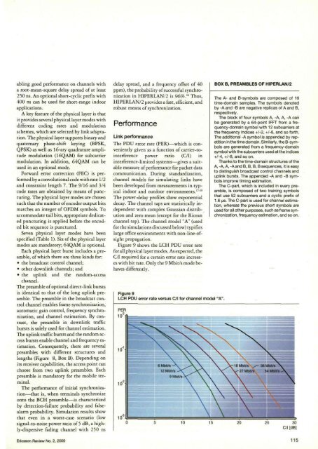
abling good performance on channels witha root-mean-square delay spread of at least250 ns. An optional short-cyclic prefix with400 ns can be used for short-range indoorapplications.A key feature of the physical layer is thatit provides several physical layer modes withdifferent coding rates and modulationschemes, which are selected by link adaptation.The physical layer supports binary andquaternary phase-shift keying (BPSK,QPSK) as well as 16-ary quadrature amplitudemodulation (16QAM) for subcarriermodulation. In addition, 64QAM can beused in an optional mode.Forward error correction (FEC) is performedby aconvolutional code with rate 1/2and constraint length 7. The 9/16 and 3/4code rates are obtained by means of puncturing.The physical layer modes are chosensuch that the number of encoder output bitsmatches an integer of OFDM symbols. Toac<strong>com</strong>modate tail bits, appropriate dedicatedpuncturing is applied before the encodedbit sequence is punctured.Seven physical layer modes have beenspecified (Table 1). Six of the physical layermodes are mandatory; 64QAM is optional.Each physical layer burst includes a preamble,of which rhere are three kinds for:• the broadcast control channel;• other downlink channels; and• the uplink and the random-accesschannel.The preamble of optional direct-link burstsis identical to that of the long uplink preamble.The preamble in the broadcast controlchannel enables frame synchronization,automatic gain control, frequency synchronization,and channel estimation. By contrast,the preamble in downlink trafficbursts is solely used for channel estimation.The uplink traffic bursts and the random accessbursts enable channel and frequency estimation.Consequently, there are severalpreambles with different structures andlengths (Figure 8, Box B). Depending onits receiver capabilities, the access point canchoose from two uplink preambles. Eachpreamble is mandatory for the mobile terminal.The performance of initial synchronization—thatis, when terminals synchronizeonto the BCH preamble—is characterizedby detection-failure probability and falsealarmprobability. Simulation results showthat even in a worst-case scenario (lowsignal-to-noise power ratio of 5 dB, a highly-dispersivefading channel with 250 nsEricsson Review No. 2, 2000delay spread, and a frequency offset of 40ppm), the probability of successful synchronizationin HIPERLAN/2 is 96%. 16 Thus,HIPERLAN/2 provides a fast, efficient, androbust means of synchronization.PerformanceLink performanceThe PDU error rate (PER)—which is convenientlygiven as a function of carrier-tointerferencepower ratio (C/I) ininterference-limited systems—gives a suitablemeasute of performance for packet data<strong>com</strong>munication. During standardization,channel models for simulating links havebeen developed from measurements in typicalindoor and outdoor environments. 17 ""The power-delay profiles show exponentialdecay. The channel taps are statistically independentwith <strong>com</strong>plex Gaussian distributionand zero mean (except for the Riceanchannel tap). The channel model "A" (usedfor the simulations discussed below) typifieslarge office environments with non-line-ofsightpropagation.Figure 9 shows the LCH PDU error rarefor all physical layer modes. As expected, theC/I required for a certain error rate increaseswith bit rate. Only the 9 Mbit/s mode behavesdifferently.Figure 9LCH PDU error rate versus C/I for channel model "A".BOX B, PREAMBLES OF HIPERLAN/2The A- and B-symbols are <strong>com</strong>posed of 16time-domain samples. The symbols denotedby -A and -B are negative replicas of A and B,respectively.The block of four symbols A, -A, A, -A canbe generated by a 64-point IFFT from a frequency-domainsymbol with 12 subcarriers atthe frequency indices +1-2, +1-6, and so forth.The additional -A symbol is appended by repetitionin the time domain. Similarly, the B-symbolsare generated from a frequency-domainsymbol with the subcarriers used at the indices+/-4, +/-8, and so on.Thanks to the time-domain structures of theA, -A, A, -A and B, B, B, B sequences, it is easyto distinguish broadcast control channels anduplink bursts. The appended -A and -B symbolsimprove timing estimation.The C-part, which is included in every preamble,is <strong>com</strong>posed of two training symbolsthat use 52 subcarriers and a cyclic prefix of1.6 us. The C-part is used for channel estimation,whereas the previous short symbols areused for all other purposes, such as frame synchronization,frequency estimation, and so on.115


