Installation and Operating Instructions TSCHAN - Tschan GmbH
Installation and Operating Instructions TSCHAN - Tschan GmbH
Installation and Operating Instructions TSCHAN - Tschan GmbH

Create successful ePaper yourself
Turn your PDF publications into a flip-book with our unique Google optimized e-Paper software.
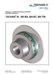
<strong>Installation</strong> <strong>and</strong> <strong>Operating</strong> <strong>Instructions</strong><br />
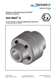
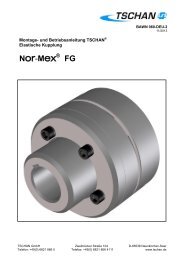
1 Function<br />
The Nor-Mex ® Coupling Type GTW/GBS is an<br />
torsionally flexible <strong>and</strong> shock-proof claw coupling with<br />
brake disc <strong>and</strong> removable claw ring. They compensate<br />
for angular as well as radial <strong>and</strong> axial shaft<br />
misalignment within fixed tolerances. The torque is<br />
transmitted through an elastic transitional ring.<br />
The elastic transitional ring made of Perbunan (Pb)<br />
with nitrile rubber as the base material dampens<br />
shocks <strong>and</strong> torsional vibrations, is oil-proof, insensitive<br />
to temperature <strong>and</strong> normally electrically conductive.<br />
This prevents undesirable static charging, among<br />
other things.<br />
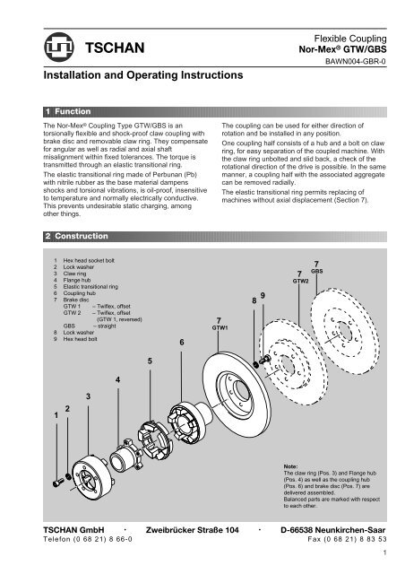
2 Construction<br />
1 2<br />
<strong>TSCHAN</strong><br />
1 Hex head socket bolt<br />
2 Lock washer<br />
3 Claw ring<br />
4 Flange hub<br />
5 Elastic transitional ring<br />
6 Coupling hub<br />
7 Brake disc<br />
GTW 1 – Twiflex, offset<br />
GTW 2 – Twiflex, offset<br />
(GTW 1, reversed)<br />
GBS – straight<br />
8 Lock washer<br />
9 Hex head bolt<br />
3<br />
4<br />
5<br />
6<br />
7<br />
GTW1<br />
The coupling can be used for either direction of<br />
rotation <strong>and</strong> be installed in any position.<br />
One coupling half consists of a hub <strong>and</strong> a bolt on claw<br />
ring, for easy separation of the coupled machine. With<br />
the claw ring unbolted <strong>and</strong> slid back, a check of the<br />
rotational direction of the drive is possible. In the same<br />
manner, a coupling half with the associated aggregate<br />
can be removed radially.<br />
The elastic transitional ring permits replacing of<br />
machines without axial displacement (Section 7).<br />
8 9<br />
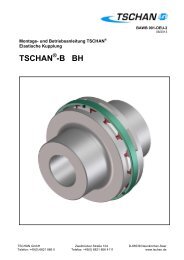
Flexible Coupling<br />
Nor-Mex ® GTW/GBS<br />
7<br />
GTW2<br />
7<br />
GBS<br />
BAWN004-GBR-0<br />
Note:<br />
The claw ring (Pos. 3) <strong>and</strong> Flange hub<br />
(Pos. 4) as well as the coupling hub<br />
(Pos. 6) <strong>and</strong> brake disc (Pos. 7) are<br />
delivered assembled.<br />
Balanced parts are marked with respect<br />
to each other.<br />
<strong>TSCHAN</strong> <strong>GmbH</strong> • Zweibrücker Straße 104 • D-66538 Neunkirchen-Saar<br />
Telefon (0 68 21) 8 66-0 Fax (0 68 21) 8 83 53<br />
1
• Remove the elastic transitional ring (Fig. 2, Pos. 1).<br />
• Clean the holes in the flange <strong>and</strong> coupling hubs, the<br />
shaft ends <strong>and</strong> the disc brake shoes before<br />
installing.<br />
• For larger couplings, use suitable installation aids.<br />
• Place the flange hub with claw ring <strong>and</strong> the coupling<br />
hub with brake disc on the shaft ends (Fig. 2,<br />
Pos. 2).<br />
Note:<br />
For easy installation, the uniform warming of the hubs<br />
to between 80 <strong>and</strong> 120° C is completely safe.<br />
2<br />
3 Observe before <strong>Installation</strong><br />
WARNING!<br />
Before performing any work on the<br />
coupling, switch off the motor!<br />
Secure the motor against switching on<br />
unintentionally!<br />
• Ensure that the intended rotational speed <strong>and</strong> the<br />
torque as well as the operating temperature do not<br />
exceed the allowable values in the current<br />
Catalogue No. 3.<br />
4 Installing the Coupling<br />
WARNING!<br />
Gloves must always be worn in order to<br />
avoid injury due to hot coupling parts!<br />
• Slide the hubs onto the shaft to achieve full<br />
engagement only, e.g. the shaft end should be flush<br />
with the end of the hub <strong>and</strong> not protrude into the<br />
claw ring (Fig. 3).<br />
Observe deviating agreements!<br />
CAUTION!<br />
Allow the hot hubs to cool before inserting the<br />
elastic transitional ring.<br />
• Before inserting the elastic ring apply lubricant<br />
(e.g. talcum).<br />
• Insert the transitional ring.<br />
• Join the shafts with the mounted coupling hubs<br />
(Fig. 4).<br />
Note:<br />
If a drive shaft with a coupling half is installed radially,<br />
unbolt <strong>and</strong> slide back the claw rings. For installation,<br />
see Section 7.<br />
• If static charging must be avoided in operation, coordination<br />
with <strong>TSCHAN</strong> is required before<br />
installation of the coupling.<br />
• The maximum allowable size of the bore diameter<br />
in the coupling hub as well as the flange hub is<br />
according to the current Catalogue No. 3.<br />
• St<strong>and</strong>ard tolerances for the bores are according to<br />
ISO Fit H7 (DIN 7161, sheet 2).<br />
• St<strong>and</strong>ard key groove according to DIN 6885,<br />
sheet 1.<br />
• Set screws as required.<br />
Fig. 2<br />
Fig. 3<br />
Fig. 4<br />
1<br />
2<br />
2
5 Coupling Alignment<br />
Recommended alignment values – angular<br />
• Measure a complete revolution (360°).<br />
Determine the largest deviation z1 as well as the<br />
smallest deviation z2 (Fig. 5).<br />
Calculate the angular misalignment ∆z = z1 – z2.<br />
• When aligning, comply with the maximum allowable<br />
angular misalignment ∆zmax according to Table 1.<br />
The values according to Table 1 apply for a<br />
reference speed of 1500 RPM.<br />
Table 1<br />
Recommended alignment values – radial<br />
• Measure a complete revolution (360°).<br />
Determine the largest deviation y1 as well as the<br />
smallest deviation y2 (Fig. 6).<br />
Calculate the radial misalignment y = 0.5 · (y1 – y2).<br />
• When aligning, comply with the maximum allowable<br />
radial misalignment ymax according to Table 2.<br />
The values according to Table 2 apply for a<br />
reference speed of 1500 RPM.<br />
Table 2<br />
WARNING!<br />
Before performing any work on the<br />
coupling, switch off the motor!<br />
Secure the motor against switching on<br />
unintentionally!<br />
Note:<br />
Exact alignment of the coupling increases the service<br />
life of the elastic transitional ring.<br />
Recommended alignment values – axial<br />
• Measure the axial assembly play S (Fig. 7).<br />
• When aligning, comply with the allowable<br />
tolerance x according to Table 3.<br />
CAUTION!<br />
If larger axial misalignments are expected in<br />
operation, coordination with <strong>TSCHAN</strong> is<br />
necessary.<br />
Fig. 5<br />
Fig. 6<br />
Table 3 Fig. 7<br />
The maximum allowable misalignments given in<br />
Tables 1 to 3 are general st<strong>and</strong>ard values. In special<br />
cases with increased dem<strong>and</strong>s on quiet running or<br />
higher RPM, an alignment accuracy of ≤ 0.1 mm in the<br />
three displacement planes can be necessary.<br />
For further information, see Factory St<strong>and</strong>ard TWN.<br />
Size 112 128 148 168 194 214 240 265 295 330 370 415<br />
∆zmax [mm] 0.3 0.3 0.3 0.3 0.3 0.3 0.3 0.3 0.3 0.3 0.3 0.3<br />
Size 112 128 148 168 194 214 240 265 295 330 370 415<br />
ymax [mm] 0.3 0.3 0.3 0.3 0.3 0.3 0.3 0.3 0.3 0.3 0.3 0.3<br />
Size 112 128 148 168 194 214 240 265 295 330 370 415<br />
S [mm] 3.5 3.5 3.5 3.5 3.5 4.0 4.0 5.5 8.0 8.0 8.0 8.0<br />
x [mm] ±1.0 ±1.0 ±1.0 ±1.5 ±1.5 ±2.0 ±2.0 ±2.5 ±2.5 ±2.5 ±2.5 ±2.5<br />
Δ z<br />
y<br />
S±x<br />
y<br />
180°<br />
180°<br />
180°<br />
180°<br />
3
• Before a check of the rotational direction of the<br />
drive system, secure the loose claw ring against<br />
axial displacement.<br />
• Before placing into operation, check the tightening<br />
torques MA1 <strong>and</strong> MA2 of the bolts according to<br />
Tables 4 <strong>and</strong> 5 (Fig. 8).<br />
• Unbolt the claw ring <strong>and</strong> slide it back (Fig. 9,<br />
Pos. 1).<br />
• Cut through the transitional ring at one of the<br />
connecting webs.<br />
• Remove the transitional ring (Fig. 9, Pos. 2). Start<br />
with the cut-through connecting web.<br />
• Apply lubricant (e.g. talcum) to a new elastic<br />
transitional ring before inserting.<br />
• Cut through the new transitional ring at one of the<br />
connecting webs <strong>and</strong> insert between coupling hub<br />
<strong>and</strong> flange hub.<br />
CAUTION!<br />
Balanced parts are marked with respect to each<br />
other. The contact surfaces of the claw ring <strong>and</strong><br />
flange hub must be clean as well as free of oil <strong>and</strong><br />
grease.<br />
• Place the claw ring in the marked position.<br />
• Tighten the bolts lightly <strong>and</strong> uniformly.<br />
• Tighten the bolts with the tightening torques MA<br />
according to Tables 4 <strong>and</strong> 5 (Fig. 8).<br />
4<br />
6 Operation<br />
Table 4<br />
Size 112 128 148 168 194 214 240 265 295 330 370 415<br />
DIN 933-8.8 M8 M8 M10 M10 M12 M12 M12 M16 M16 M16 M16 M16<br />
MA1 [Nm] 25 25 49 49 85 85 85 210 210 210 210 210<br />
Table 5<br />
Size 112 128 148 168 194 214 240 265 295 330 370 415<br />
DIN 912-8.8 M8 M8 M10 M10 M10<br />
DIN 912-10.9 M12 M12 M14 M14 M16 M16 M16<br />
MA2 [Nm] 25 25 49 49 49 125 125 200 200 310 310 310<br />
WARNING!<br />
Before placing into operation, all moving<br />
parts must be covered with stationary<br />
protective devices.<br />
The Nor-Mex ® Coupling Type GTW/GBS requires little<br />
maintenance in operation.<br />
Check during routine control of the drive system:<br />
• Alignment of the coupling<br />
• Condition of the elastomer<br />
7 Replacing the Elastic Transitional Ring<br />
WARNING!<br />
Before performing any work on the<br />
coupling, switch off the motor!<br />
Secure the motor against switching on<br />
unintentionally!<br />
Fig. 8<br />
Fig. 9<br />
M A2<br />
1<br />
2<br />
M A1<br />
During maintenance work on the drive system or after<br />
five years at the latest:<br />
• Replace the elastic transitional ring.<br />
Note:<br />
If a coupling half with the associated aggregate is lifter<br />
radially, the transitional ring can be axially replaced.<br />
The coupling must again be aligned (see Section 5).<br />
WARNING!<br />
Before placing into operation, install all<br />
protective devices!