
You also want an ePaper? Increase the reach of your titles
YUMPU automatically turns print PDFs into web optimized ePapers that Google loves.
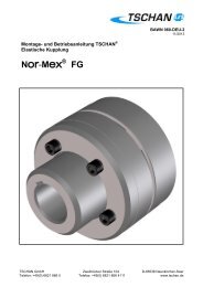
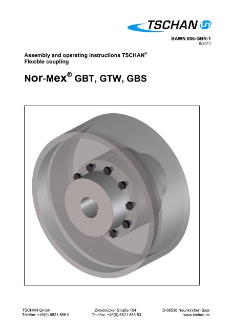
Assembly and operating instructions TSCHAN ®<br />
Flexible coupling<br />
<strong>Nor</strong>-<strong>Mex</strong> ® GBT, GTW, GBS<br />
BAWN 006-GBR-1<br />
8/2011<br />
TSCHAN <strong>GmbH</strong> Zweibrücker Straße 104 D-66538 Neunkirchen-Saar<br />
Telefon: +49(0) 6821 866 0 Telefax: +49(0) 6821 883 53 www.tschan.de
Content<br />
Chapter Page<br />
1 Notes on safety ................................................................................................................ 2<br />
2 Function ........................................................................................................................... 3<br />
2.1 Appropriate Use ......................................................................................................... 3<br />
3 Marking of the coupling .................................................................................................... 4<br />
4 Storage ............................................................................................................................ 4<br />
5 Construction ..................................................................................................................... 5<br />
6 Technical data .................................................................................................................. 6<br />
7 Assembly ......................................................................................................................... 8<br />
7.1 Pay attention before the assembly ............................................................................ 8<br />
7.2 Finished borehole ...................................................................................................... 9<br />
7.3 Installing coupling .................................................................................................... 10<br />
8 Adjusting coupling .......................................................................................................... 11<br />
8.1 Angular misalignment ∆Kw ....................................................................................... 12<br />
8.2 Radial displacement ∆Kr .......................................................................................... 12<br />
8.3 Axial displacement ................................................................................................... 13<br />
9 Operation ....................................................................................................................... 14<br />
9.1 Check of Direction of Rotation ................................................................................. 17<br />
10 Maintenance................................................................................................................... 19<br />
10.1 Wear Inspection on the Buffer Ring ......................................................................... 19<br />
10.2 Wear limit of elastic buffers...................................................................................... 20<br />
10.3 Changing the elastic intermediate ring .................................................................... 21<br />
10.4 Assembly brake drum/disk....................................................................................... 22<br />
11 Waste Disposal .............................................................................................................. 22<br />
1 Notes on safety<br />
The present assembly and operating instruction (AOI) constituents a part of the coupling<br />
supply. Always keep the AOI near the coupling well accessible.<br />
The German version of this manual is the predominant and binding version.<br />
Make sure that all persons charged with the assembly, operating, service, and maintenance<br />
have read and understood the AOI and follow all the points:<br />
- Avert hazards for body and live of the user and third parties.<br />
- Ensure the operating safety of the coupling.<br />
- Avoid the loss of use and environmental impairment through false handling.<br />
In the case of transport, mounting, dismounting and maintenance, attention is to be paid to<br />
the relevant regulations for industrial safety and for environmental care.<br />
The coupling may only be operated, mounted, serviced and maintained by authorised and<br />
trained personnel.<br />
bawn006-gbr-1 <strong>Nor</strong>-<strong>Mex</strong> ® GBT, GTW, GBS - 2 -
The user must take into account that the bolting elements of coupling parts may be adversely<br />
affected by the heat produced by a brake disk/ brake drum due to the resultant friction. Make<br />
sure that the combination of the employed brake lining with the material of the brake disk/<br />
brake drum does not lead to sparks or impermissible thermal growth. The brake disk is<br />
normally made of steel, and the brake drum is normally made of cast iron with nodular<br />
graphite. In case of any doubt, please consult the supplier!<br />
In the interest of further development, we reserve the right to make changes which serve<br />
technological progress.<br />
By the use of accessories and spare parts, which were not originally manufactured by<br />
TSCHAN <strong>GmbH</strong>, we are not responsible for any resulting damage or liability or guarantee.<br />
2 Function<br />
The coupling <strong>Nor</strong>-<strong>Mex</strong> ® -GBT, GTW, GBS is a torsionally elastic and puncture-proof claw<br />
coupling.<br />
It balances out angular, radial, and axial shaft misalignments within defined limits. The<br />
coupling transfers the torque via pressure loadable, elastic buffers of Perbunan (Pb) which<br />
are joined together as an intermediate ring.<br />
The elastic intermediate ring can cushion impacts and torsional vibrations; it is oil-tight and<br />
electrically conductive.<br />
The elastic intermediate ring can be changed without axially shifting the machine.<br />
The coupling is usable in every sense of rotation and installation position.<br />
2.1 Appropriate Use<br />
• The coupling must only be operated in normal industrial atmospheres. Since aggressive<br />
media may attack the coupling components, screws and elastic buffer rings, they<br />
represent a risk for the operational safety of the coupling. Consult TSCHAN <strong>GmbH</strong> in<br />
such cases.<br />
• In order to ensure a faultless, lasting operation of the coupling it must be laid out according<br />
to the layout instructions e.g. DIN 740 part 2 (or also catalogue <strong>Nor</strong>-<strong>Mex</strong> ® ) with an<br />
operating facture corresponding to the operating conditions.<br />
• Apart from incorporating a finished bore hole with parallel key groove (see “7.2 Finished<br />
borehole”) no further changes can be carried out on the coupling.<br />
• The coupling may only be used within the framework of the conditions defined in the<br />
performance and delivery contract.<br />
• Every change of the conditions of use or the operating parameters necessitates a new<br />
verification of the coupling layout.<br />
bawn006-gbr-1 <strong>Nor</strong>-<strong>Mex</strong> ® GBT, GTW, GBS - 3 -
3 Marking of the coupling<br />
The product line <strong>Nor</strong>-<strong>Mex</strong> ® has its hardness in Shore (A) indicated on the elastic intermediate<br />
ring.<br />
4 Storage<br />
On receipt of the goods, the supply is to be checked immediately for completeness and<br />
correctness. Possible damages incurred during transit and / or missing parts are to be<br />
notified in writing.<br />
The coupling parts can be stored in their delivered standard-state for 6 months in a dry,<br />
roofed place at normal room temperature. For a longer storage duration a long-term preservation<br />
is necessary (consult TSCHAN <strong>GmbH</strong>). The elastic intermediate ring must not be<br />
subjected to ozone containing mediums, direct solar influence or strong light sources with<br />
ultraviolet-light. The relative humidity must not exceed 65%. In the case of proper storage the<br />
characteristics of the elastic intermediate ring remain unchanged for almost up to three years.<br />
bawn006-gbr-1 <strong>Nor</strong>-<strong>Mex</strong> ® GBT, GTW, GBS - 4 -
5 Construction<br />
1. Pan-head screw DIN 912<br />
2. Locking washer (caging-washer)<br />
1 Pan-head 3. screw Claw ring DIN part 912 102<br />
2 Locking 4. washer Flange (caging-washer)<br />
hub part 104<br />
3 Claw ring 5. part Elastic 102…0X3 intermediate ring part 010<br />
4 Flange 6. hub Coupling part 104 hub part 108<br />
5 Elastic 7. intermediate Brake drum ring part part 500 010<br />
6 Coupling 8. flange Twiflex-brake FE/FG part disk 102…0X4 part 506<br />
9. Locking washer (caging-washer)<br />
10. Hexagon head screw DIN 933<br />
Fig. 1 Construction <strong>Nor</strong>-<strong>Mex</strong> ® GBT, GTW<br />
Details:<br />
Claw ring (Pos. 3) and flange hub (Pos. 4), coupling hub (Pos. 6) and brake drum/disk (Pos.<br />
7/8) are always delivered screwed together.<br />
Balanced parts are match marked to each other.<br />
bawn006-gbr-1 <strong>Nor</strong>-<strong>Mex</strong> ® GBT, GTW, GBS - 5 -
6 Technical data<br />
Table 1 Technical Data:<br />
size<br />
<strong>Nor</strong>-<strong>Mex</strong><br />
TCnom<br />
Pb72<br />
[Nm]<br />
TCpeak<br />
Pb72<br />
[Nm]<br />
TCnom<br />
Pb82<br />
[Nm]<br />
TCpeak<br />
Pb82<br />
[Nm]<br />
112 150 310 230 540<br />
128 250 500 380 650<br />
148 390 800 600 1350<br />
168 630 1300 980 1800<br />
194 1050 2000 1650 2400<br />
214 1500 3100 2400 4200<br />
240 2400 4800 3700 6200<br />
265 3700 7500 5800 8300<br />
295 4900 10000 7550 10500<br />
330 6400 13000 9900 14500<br />
370 8900 18200 14000 20000<br />
415 13200 27000 20500 27000<br />
Table 2 <strong>Nor</strong>-<strong>Mex</strong> ® GBT:<br />
d5<br />
[mm]<br />
DB-B<br />
[Nm]<br />
TBR<br />
[Nm]<br />
nmax<br />
[min -1 ]<br />
d2<br />
max<br />
[mm]<br />
Fig. 2 <strong>Nor</strong>-<strong>Mex</strong> ® GBT, GTW<br />
d6<br />
max<br />
[mm]<br />
d4<br />
[mm]<br />
d7<br />
[mm]<br />
lE<br />
[mm]<br />
bawn006-gbr-1 <strong>Nor</strong>-<strong>Mex</strong> ® GBT, GTW, GBS - 6 -<br />
lG<br />
[mm]<br />
LG<br />
[mm]<br />
C<br />
[mm]<br />
S1<br />
[mm]<br />
S2<br />
[mm]<br />
z x M x Ls<br />
DIN 933 8.8<br />
MA<br />
[Nm]<br />
m<br />
undrilled<br />
[kg]<br />
112 200-75 450 4200 46 42 64,5 68 60 58 133 11,0 3,5±1,0 15±1,0 6 x M8 x 20 25 10,2<br />
128 200-75 550 4200 53 52 74,5 85 70 68 154 16,0 3,5±1,0 16±1,0 6 x M8 x 25 25 13,0<br />
148 250-95 1000 3400 65 58 92,5 94 80 78 176 16,0 3,5±1,0 18±1,0 6 x M10 x 25 49 21,5<br />
168<br />
250-95<br />
1600 3400<br />
315-118 2700<br />
75 72 104,5 118 90 87 198<br />
19,0<br />
8,0<br />
3,5±1,5 21±1,5<br />
8 x M10 x 30<br />
8 x M10 x 30<br />
49<br />
27,8<br />
37,0<br />
194 315-118 2750 2700 85 85 121,5 138 100 97 221 16,5 3,5±1,5 24±1,5 8 x M12 x 30 85 45,4<br />
214<br />
315-118<br />
3350 2700<br />
400-150 2100<br />
95 92 135,5 153 110 107 243<br />
19,0<br />
12,5<br />
4,0±2,0 26±2,0 9 x M12 x 35 85<br />
55,6<br />
71,4<br />
240<br />
450-150<br />
4200 2100<br />
500-190 1700<br />
100 102 146,0 168 120 117 267<br />
18,0<br />
9,0<br />
4,0±2,0 30±2,0 10 x M12 x 35 85<br />
83,5<br />
110,5<br />
265 500-190 8700 1700 115 120 164,0 198 140 137 310 22,0 5,5±2,5 33±2,5 10 x M16 x 40 210 134,4<br />
295<br />
500-190<br />
9800 1700<br />
630-236 1360<br />
130 130 181,0 214 150 147 334<br />
30,0<br />
5,0<br />
8,0±2,5<br />
10 x M16 x 40<br />
37±2,5<br />
10 x M16 x 45<br />
210<br />
210<br />
155,5<br />
209,1<br />
330<br />
630-236<br />
710-265<br />
10600<br />
1360<br />
1200<br />
135 150 208,0 248 160 156 356<br />
11,0<br />
0,0<br />
8,0±2,5 40±2,5 10 x M16 x 45 210<br />
240,2<br />
278,3<br />
370 710-265 13500 1200 160 170 241,0 278 180 176 399 15,0 8,0±2,5 43±2,5 11 x M16 x 45 210 332,0<br />
415 710-265 16000 1200 180 185 275,0 308 200 196 441 25,0 8,0±2,5 45±2,5 12 x M16 x 55 210 414,3
Table 3 <strong>Nor</strong>-<strong>Mex</strong> ® GTW:<br />
d5<br />
A-G<br />
TBR<br />
nmax<br />
d2<br />
max<br />
[mm]<br />
d6<br />
max<br />
[mm]<br />
d4<br />
d7<br />
lE<br />
bawn006-gbr-1 <strong>Nor</strong>-<strong>Mex</strong> ® GBT, GTW, GBS - 7 -<br />
lG<br />
LG<br />
C1<br />
C2<br />
S1<br />
S2<br />
z x M x Ls<br />
MA<br />
m<br />
undrilled<br />
[kg<br />
9,0<br />
[mm] [Nm] [Nm] [min -1 ]<br />
[mm] [mm] [mm] [mm] [mm] [mm] [mm] [mm] [mm] DIN 933 8.8 [Nm]<br />
112<br />
250-12,7<br />
450 4580<br />
300-12,7 3820<br />
46 42 64,5 68 60 58 133<br />
55,8<br />
53,8<br />
2,5<br />
-2,5<br />
3,5±1,0 15±1,0<br />
6 x M8 x 16<br />
6 x M8 x 22<br />
25<br />
12,0<br />
128 300-12,7 550 3820 53 52 74,5 85 70 68 154 60,8 4,5 3,5±1,0 16±1,0 6 x M8 x 25 25 14,7<br />
148 300-12,7 1000 3820 65 58 92,5 94 80 78 176 67,8 11,5 3,5±1,0 18±1,0 6 x M10 x 25 49 18,8<br />
168<br />
356-12,7<br />
406-12,7<br />
1600<br />
3225<br />
2825<br />
75 72 104,5 118 90 87 198<br />
81,8<br />
84,8<br />
2,5 3,5±1,5 21±1,5 8 x M10 x 30 49<br />
28,8<br />
31,6<br />
194<br />
406-12,7<br />
457-12,7<br />
2750<br />
2825<br />
2510<br />
85 85 121,5 138 100 97 221<br />
90,8<br />
87,8<br />
8,5 3,5±1,5 24±1,5 8 x M12 x 30 85<br />
40,6<br />
45,6<br />
214<br />
406-12,7<br />
457-12,7<br />
3350<br />
2825<br />
2510<br />
95 92 135,5 153 110 107 243<br />
96,8<br />
93,8<br />
14,5 4,0±2,0 26±2,0<br />
9 x M12 x 30<br />
9 x M12 x 35<br />
85<br />
50,2<br />
55,2<br />
240<br />
457-12,7<br />
514-12,7<br />
4200<br />
2510<br />
2230<br />
100 102 146,0 168 120 117 267 100,8 21,5 4,0±2,0 30±2,0 10 x M12 x 35 85<br />
67,2<br />
72,2<br />
265<br />
457-12,7<br />
514-12,7<br />
8700<br />
2510<br />
2230<br />
115 120 164,0 198 140 137 310 115,8 36,5 5,5±2,5 33±2,5 10 x M16 x 35 210<br />
90,8<br />
95,8<br />
295<br />
514-12,7<br />
610-12,7<br />
9800<br />
2230<br />
1880<br />
130 130 181,0 214 150 147 334 123,8 44,5 8,0±2,5 37±2,5 10 x M16 x 35 210<br />
117,0<br />
128,0<br />
330<br />
514-12,7<br />
10600<br />
610-12,7<br />
2230<br />
1880<br />
135 150 208,0 248 160 156 356 129,8 50,5 8,0±2,5 40±2,5 10 x M16 x 40 210<br />
148,0<br />
159,0<br />
370<br />
610-12,7<br />
13500<br />
1880<br />
160 170 241,0 278 180 176 399 143,8<br />
711-12,7 1615 140,8<br />
64,5 8,0±2,5<br />
11 x M16 x 40<br />
43±2,5<br />
11 x M16 x 45<br />
210<br />
210,9<br />
226,6<br />
610-12,7 1880<br />
160,8<br />
12 x M16 x 40<br />
280,8<br />
415<br />
711-12,7<br />
16000<br />
812-12,7<br />
915-12,7<br />
1615<br />
1410<br />
1255<br />
180 185 275,0 308 200 196 441<br />
157,8<br />
151,8<br />
81,5 8,0±2,5<br />
12 x M16 x 45<br />
45±2,5<br />
12 x M16 x 50<br />
210<br />
296,2<br />
329,2<br />
359,6<br />
The torque TCnom and TCpeak is valid for:<br />
- Intermediate rings of Perbunan Pb72 and/or Pb82,<br />
- Ambient temperatures of -30 °C to +60 °C,<br />
- Operation within the stipulated alignment values.<br />
During the layout of the coupling according to DIN 740 part 2 (or also catalogue <strong>Nor</strong>-<strong>Mex</strong> ® )<br />
different factors must be considered:<br />
- with higher temperatures a corresponding temperature factor Sυ<br />
- according to the starting frequency a starting factor Sz<br />
- in dependence on the operating conditions an impact factor, SA, SL<br />
With circumferential speeds of more than 22 m/s, we recommend to balance the coupling.<br />
For GBS see installation drawing
7 Assembly<br />
7.1 Pay attention before the assembly<br />
• Danger of injuries!<br />
• Disconnect the drive before carrying out any work on the coupling!<br />
• Secure the drive against unintentional re-start and rotation!<br />
• Incorrectly tightened bolts can cause serious personal injuries and<br />
property damages!<br />
• Assemble the coupling outside of the danger zone. Take care that<br />
suitable transportation means are at disposal and that the transportation<br />
ways are free of obstacles.<br />
• In compliance with accident prevention regulations, you are<br />
obliged to protect all freely rotating parts by means of permanently<br />
installed guards/ covers against unintentional contact and falling<br />
down objects.<br />
• To avoid sparks, the covers for couplings used should be made of<br />
stainless steel!<br />
• As a minimum, the covers have to fulfil the requirements of protection<br />
type IP2X.<br />
• The covers have to be designed to prevent dust from depositing on<br />
the coupling.<br />
• The cover must not contact the coupling or impair the proper<br />
function of the coupling.<br />
• Make sure that the intended rotational speeds and torques as well as the ambient temperatures<br />
do not exceed the values indicated in “6 Technical Data”.<br />
• The maximum permissible borehole diameter must not be exceeded.<br />
• Check whether the shaft hub connections can safely transmit the occurring operating<br />
torques.<br />
• The standard TSCHAN tolerance for the finished boreholes is fit H7.<br />
• Standard parallel key slot is according to DIN 6885 page 1.<br />
• Check the dimensions and tolerances of shafts, hub boreholes, parallel key and slot.<br />
• Adjust setscrews as required.<br />
bawn006-gbr-1 <strong>Nor</strong>-<strong>Mex</strong> ® GBT, GTW, GBS - 8 -
7.2 Finished borehole<br />
For the completion of the finished borehole in a coupling hub, pay attention to following<br />
procedure:<br />
• Clean the coupling hub of preservatives.<br />
• Tighten the coupling hub to the faces labelled with ⎡and carefully align the coupling hub.<br />
• The indicated values in table 2 and 3 for ød2max and ød6max are valid for a parallel key<br />
connection according to DIN 6885/1 and must not be exceeded.<br />
• Choose the borehole fit so that during the union with the shaft tolerance a wringing fit<br />
and/or an interference fit as for example at H7/m6 is carried out.<br />
• Provide a setscrew for axial securing on the hub back above the parallel key slot.<br />
In the case of other shaft hub connections consultation with TSCHAN <strong>GmbH</strong> is necessary.<br />
• The maximum indicated borehole diameters are valid for a parallel<br />
key connection according to DIN 6885/1 and must not be exceeded.<br />
• In the case of transgression of these values the coupling can<br />
sever.<br />
• Through flying away fragments danger exists!<br />
bawn006-gbr-1 <strong>Nor</strong>-<strong>Mex</strong> ® GBT, GTW, GBS - 9 -
7.3 Installing coupling<br />
• Remove the elastic intermediate ring (Figure<br />
3, pos. 1).<br />
• Clean the borehole of the flange hub and the<br />
shaft end before installing. The surfaces must<br />
be clean, dry and grease-free.<br />
• Use suitable installation aids and hoists such<br />
as cranes or pulley blocks in the case of<br />
bigger couplings.<br />
• Pull the pre-mounted coupling halves in the<br />
intended position on the shaft ends (Figure 3,<br />
pos. 2).<br />
Fig. 4<br />
Fig. 3<br />
Reference:<br />
For easier installation a uniform warming of the hub to 80 °C to 120 °C is safe.<br />
� Warning!<br />
� Only work with gloves as a protection against hot parts of the<br />
coupling!<br />
• Mount the hub so that the shaft ends<br />
are flush with the interior borehole<br />
opening (Figure 4).<br />
Pay attention to possible differing<br />
agreements!<br />
• Secure possible available setscrews<br />
by tightening with an adhesive e.g.<br />
Loctite 222 against automatic loosening<br />
and flying out.<br />
bawn006-gbr-1 <strong>Nor</strong>-<strong>Mex</strong> ® GBT, GTW, GBS - 10 -
ATTENTION!<br />
Let the hot hub cool off to ambient temperature before the introduction of the intermediate<br />
ring.<br />
• For easier mounting the elastic intermediate<br />
ring can be provided with a slip additive (e.g.<br />
Talcum) before introduction.<br />
• Fit the intermediate ring into one half of the<br />
coupling<br />
• Push the shaft end with the mounted<br />
coupling halves together (Figure 5).<br />
• Adjust the coupling according to the following<br />
specifications in “8 Coupling adjustment”.<br />
8 Adjusting coupling<br />
� Injury hazard!<br />
Fig. 5<br />
� Switch-off the drive before all work on the coupling!<br />
� Secure the drive against unintentional switching on and rotating!<br />
� Reference:<br />
� An exact alignment of the coupling increases the service life of the<br />
elastic intermediate ring.<br />
� Do not exceed the maximum permissible displacement values. The<br />
overstepping of these values results in coupling damage and<br />
breakdown!<br />
• When aligning the cold equipment take into account the expected thermal growth of the<br />
components, so that the permissible misalignment values for the coupling are not<br />
exceeded in operation.<br />
• Be aware that the coupling under misalignment imposes restoring forces on the adjacent<br />
shafts and bearings. Take into account that the larger the misalignment, the greater the<br />
restoring forces will be.<br />
• The displacements values indicated in the tables 4 to 6 are maximum permissible guide<br />
numbers.<br />
We recommend not to fully utilise these values during the alignment, so that in operation<br />
sufficient reserves remain for thermal expansions, foundation settlements etc.<br />
• In special cases with high demands on quiet running or high rotating speeds it is possible<br />
that, in the three displacement levels, an alignment accuracy of ≤ 0,1 mm is necessary.<br />
• If the coupling is mounted in a closed housing / casing so that a subsequent alignment is<br />
not possible any more, it must be guaranteed that the geometry and fit accuracy of the<br />
contact surfaces in operation aligns the shafts exactly within the mentioned tolerances.<br />
bawn006-gbr-1 <strong>Nor</strong>-<strong>Mex</strong> ® GBT, GTW, GBS - 11 -
8.1 Angular misalignment ∆Kw<br />
• Measure on the face of the<br />
external diameter a complete<br />
rotation (360°). Determine in this<br />
case the greatest deviation ∆Kw1<br />
as well as the smallest deviation<br />
∆Kw2 (Figure 6).<br />
• Calculate the angular misalignment<br />
∆Kw = ∆Kw1 - ∆Kw2.<br />
• The values in table 4 are valid for<br />
a reference rotation speed of<br />
1500 min -1 .<br />
Table 4 Maximum permissible displacement values - angular:<br />
Size 112 128 148 168 194 214 240 265 295 330 370 415<br />
∆Kw max [mm] 0,3 0,3 0,3 0,3 0,3 0,3 0,3 0,3 0,3 0,3 0,3 0,3<br />
8.2 Radial displacement ∆Kr<br />
• Measure a complete rotation (360°).<br />
Determine in this case the greatest<br />
deviation ∆Kr1 as well as the smallest<br />
deviation ∆Kr2 (Figure 7).<br />
• Calculate the radial displacement<br />
∆Kr = 0,5 x (∆Kr1 - ∆Kr2). Pay attention<br />
to the operational sign of the<br />
measured values.<br />
• The values of table 5 are valid for a<br />
reference rotation speed of<br />
1500 min -1 .<br />
Fig. 6<br />
Fig. 7<br />
Table 5 Maximum permissible displacement values - radial:<br />
Size 112 128 148 168 194 214 240 265 295 330 370 415<br />
∆Kr max [mm] 0,3 0,3 0,3 0,3 0,3 0,3 0,3 0,3 0,3 0,3 0,3 0,3<br />
bawn006-gbr-1 <strong>Nor</strong>-<strong>Mex</strong> ® GBT, GTW, GBS - 12 -
8.3 Axial displacement<br />
• Measure the axial S1 gap measurement<br />
according to figure 8.<br />
• Keep, when aligning the gap measurement S,<br />
to the maximum permissible tolerance X<br />
according to table 6.<br />
ATTENTION!<br />
If greater axial displacements are expected in<br />
operation, consultation with TSCHAN <strong>GmbH</strong> is<br />
necessary.<br />
Fig. 8<br />
Table 6 Recommended alignment values - axial:<br />
Size 112 128 148 168 194 214 240 265 295 330 370 415<br />
S [mm] 3,5 3,5 3,5 3,5 3,5 4 4 5,5 8 8 8 8<br />
X [mm] ±1 ±1 ±1 ±1,5 ±1,5 ±2 ±2 ±2,5 ±2,5 ±2,5 ±2,5 ±2,5<br />
bawn006-gbr-1 <strong>Nor</strong>-<strong>Mex</strong> ® GBT, GTW, GBS - 13 -
9 Operation<br />
When using the coupling attention is to be paid to its characteristics (see „6 Technical data”).<br />
These can in no case be exceeded without having a written agreement from TSCHAN<br />
<strong>GmbH</strong>.<br />
In order to guarantee a faultless, lasting operation of the coupling, it must be laid out according<br />
to the regulations e.g. DIN 740 part 2 (or according to catalogue <strong>Nor</strong>-<strong>Mex</strong> ® ) with an<br />
operating factor corresponding to its operating conditions.<br />
Every change of the conditions of use or the operating parameters makes an inspection of<br />
the coupling layout urgently necessary.<br />
� Injury danger!<br />
� Switch-off the drive before all work on the coupling!<br />
� Secure the drive against unintentional switch-on and rotating!<br />
� Due to incorrectly tightened screws parts can fly away and cause<br />
serious injuries to persons and damage to material!<br />
� Check before commissioning the coupling the alignment and all<br />
screw fastenings for their specified tightening torque and/or firm<br />
seating!<br />
� Before commissioning the plant install all protective devices<br />
against unintentional touching of free moving and/or rotating parts.<br />
� To avoid sparks coverings in stainless steel should be used.<br />
� The coverings must fulfil at least the protection type IP2X.<br />
� The covering is to be so designed that it does not deposit dust onto<br />
the coupling parts.<br />
� The covering must not touch the coupling or influence it in its<br />
functioning.<br />
Pay attention during the operation of the coupling to:<br />
� Changed running noises<br />
� Occurring vibrations<br />
Attention!<br />
• If irregularities are found during operation of the coupling, the drive must be<br />
immediately switched off.<br />
• Detect according to the following table 7, “Operating faults and their possible causes” the<br />
faults and remove.<br />
The listed faults are some examples which are supposed to facilitate fault location.<br />
• For fault finding and elimination all machine components and operating states are<br />
to be considered!<br />
bawn006-gbr-1 <strong>Nor</strong>-<strong>Mex</strong> ® GBT, GTW, GBS - 14 -
Table 7 Operating faults and their possible causes:<br />
Trouble Cause Risk Warning Correction<br />
Irregular<br />
running<br />
noises/<br />
vibrations<br />
Premature<br />
wear of<br />
elastomer<br />
Alignment fault Considerable<br />
increase in<br />
coupling temperature.<br />
Premature<br />
wear of elastic<br />
buffers. Increased<br />
reaction forces act<br />
on connected<br />
Elastomer<br />
worn out<br />
machines.<br />
Coupling claws<br />
strike against<br />
each other. Spark<br />
formation, claw<br />
fracture, increased<br />
reaction<br />
forces.<br />
Unbalance Considerable<br />
increase in<br />
coupling temperature.<br />
Premature<br />
wear of elastic<br />
buffers. Increased<br />
reaction forces act<br />
on connected<br />
machines<br />
Loose<br />
screw<br />
connections<br />
Flying off parts<br />
can cause serious<br />
injuries and<br />
considerable<br />
damages.<br />
Alignment fault Considerable<br />
increase in<br />
coupling temperature.<br />
Increased<br />
reaction forces act<br />
on connected<br />
machines.<br />
- Disconnect drive<br />
- Remove cause for alignment fault<br />
- Re-align coupling<br />
- Inspect elastomer for wear<br />
- Disconnect drive<br />
- Check coupling components for<br />
damages and replace parts, if necessary<br />
- Replace elastomer<br />
- Disconnect drive<br />
- Verify balance state of plant components<br />
and correct it, if necessary<br />
- Inspect elastomer for wear<br />
- Disconnect drive<br />
- Check coupling parts for damages,<br />
replace parts, if necessary<br />
- Verify alignment of coupling<br />
- Tighten screws to the specified<br />
tightening torque and secure them<br />
against working loose, if necessary,<br />
- Inspect elastomer for wear<br />
- Disconnect drive<br />
- Remove cause for alignment fault<br />
- Re-align coupling<br />
- Inspect elastomer for wear<br />
bawn006-gbr-1 <strong>Nor</strong>-<strong>Mex</strong> ® GBT, GTW, GBS - 15 -
Trouble Cause Risk Warning Correction<br />
Claw breakage <br />
Unacceptabletemperatures<br />
Contact<br />
with<br />
aggressive<br />
products<br />
Torsional<br />
vibrations<br />
in the drive<br />
line<br />
Wear limit<br />
of elastomer<br />
exceeded<br />
===><br />
contact of<br />
claws<br />
Overload<br />
due to too<br />
high torque<br />
Material properties<br />
of elastic<br />
buffers change.<br />
The torque<br />
transmission<br />
capability is<br />
adversely af-<br />
fected.<br />
Material properties<br />
of elastic<br />
buffers change.<br />
The torque<br />
transmission<br />
capability is<br />
adversely affected.<br />
Considerable<br />
increase in<br />
coupling temperature.<br />
Premature<br />
wear of elastic<br />
buffers. Increased<br />
reaction forces act<br />
on connected<br />
machines.<br />
Coupling is<br />
destroyed.<br />
Connected<br />
machines can be<br />
affected, too.<br />
Coupling is<br />
destroyed.<br />
Connected<br />
machines can be<br />
affected, too.<br />
- Disconnect drive<br />
- Replace elastomer<br />
- Re-align coupling<br />
- Adjust ambient temperature<br />
- Disconnect drive<br />
- Check coupling parts for damages<br />
and replace parts, if necessary<br />
- Replace elastomer<br />
- Verify alignment of coupling<br />
- Prevent contact with aggressive<br />
products<br />
- Disconnect drive<br />
- Analyse and eliminate cause for<br />
torsional vibrations<br />
- Check coupling parts for damages<br />
and replace parts, if necessary<br />
- Replace elastomer and consult<br />
TSCHAN <strong>GmbH</strong> concerning eventual<br />
use of another Shore-hardness<br />
- Verify coupling alignment<br />
- Disconnect drive<br />
- Replace coupling<br />
- Inspect the elastomer for wear at<br />
shorter intervals<br />
- Disconnect drive<br />
- Verify coupling design in cooperation<br />
with TSCHAN <strong>GmbH</strong><br />
- Replace coupling<br />
- Install larger coupling, if necessary<br />
bawn006-gbr-1 <strong>Nor</strong>-<strong>Mex</strong> ® GBT, GTW, GBS - 16 -
9.1 Check of Direction of Rotation<br />
� Injury danger!<br />
� Switch-off the drive before all work on the coupling!<br />
� Secure the drive against unintentional switching on and rotating!<br />
� Due to incorrectly screwed on screws, parts can fly away and<br />
cause person and material damage!<br />
� Check before commissioning the coupling the alignment and all<br />
screw fixings for their specified tightening torque and/or firm seating!<br />
� Before commissioning the plant all protective devices against<br />
unintentional touching of free moving and/or rotating parts must be<br />
installed.<br />
� To avoid sparks coverings should be made of stainless steel!<br />
� The coverings must fulfil at least the protection type IP2X.<br />
� The covering is to be designed in such a way that it does not<br />
deposit dust onto the coupling parts.<br />
� The covering must not touch the coupling and/or influence it in its<br />
function.<br />
• Remove the fixing screws on the<br />
claw ring and push it back (Figure 9,<br />
Pos. 1).<br />
• Secure the claw ring against unintentional<br />
displacement.<br />
• Cut through the intermediate ring at a<br />
connecting part (Figure 9, pos. 2).<br />
• Pull out the intermediate ring. Start at<br />
the cut through connecting part.<br />
Fig. 9<br />
• Attention!<br />
• Make sure, that the coupling halves can not move axially during the<br />
sense of rotation test.<br />
• The coupling half with the pulled back claw ring must remain<br />
stationary during the sense of rotation test.<br />
• The rotating half must not touch the stationary half!<br />
• Check the direction of rotation.<br />
• Cut through a new intermediate ring at a connecting part and fit it between coupling hub<br />
and flange.<br />
• To obtain an easier mounting one can provide the new elastic intermediate ring with a slip<br />
additive before its introduction (e.g. talcum powder).<br />
bawn006-gbr-1 <strong>Nor</strong>-<strong>Mex</strong> ® GBT, GTW, GBS - 17 -
Attention!<br />
The bearing surface of the claw ring and flange hub must be clean, dry and greasefree.<br />
Balanced parts are position marked to each other.<br />
• Mount the claw ring in its marked position with<br />
respect to the hub. Pay attention that the joining<br />
parts do not tilt on the centring seat and to<br />
the position of the abrasive marking. (see<br />
chapter 10).<br />
• Slightly tighten the screws uniformly.<br />
• Tighten the claw ring threaded joint with the<br />
tightening torque MA stipulated in table 8 (Figure<br />
10).<br />
• Check the alignment of the coupling according<br />
to the specifications in „8 Coupling adjustment”.<br />
Fig. 10<br />
Table 8 Tightening torques MA of the claw ring threaded joint:<br />
Size 112 128 148 168 194 214 240 265 295 330 370 415<br />
DIN 912- 8.8 M8 M8 M10 M10 M10<br />
DIN 912-10.9 M12 M12 M14 M14 M16 M16 M16<br />
MA [Nm] 25 25 49 49 49 125 125 200 200 310 310 310<br />
bawn006-gbr-1 <strong>Nor</strong>-<strong>Mex</strong> ® GBT, GTW, GBS - 18 -
10 Maintenance<br />
The elastic coupling <strong>Nor</strong>-<strong>Mex</strong> ® - GBT, GTW, GBS have in operation a low-maintenance.<br />
Reaching the wear limit of the elastic intermediate ring depends on the operating parameters<br />
and the conditions of use.<br />
In the case of routine monitoring work on the plant check:<br />
• Alignment of the coupling<br />
• Elastomer state<br />
• Remove dust deposits from the coupling parts and the intermediate ring<br />
10.1 Wear Inspection on the Buffer Ring<br />
� Danger of injuries!<br />
� Disconnect the drive before carrying out any work on the<br />
coupling!<br />
� Secure the drive against unintentional switching on and rotating!<br />
Perform a visual inspection and a wear inspection of the buffer ring after<br />
2000 hours, or after 3 months at latest, after the first start-up of the equipment.<br />
If only minor wear or no wear is observed, further inspections of the<br />
plant can be carried out at regular intervals of 4000 hours, however, at<br />
least once a year, if the operating modes and conditions of the plant<br />
remain unchanged. However, should you observe excessive wear on the<br />
occasion of this first inspection already, check whether the cause for the<br />
problem is listed in table 7 “Operation faults and possible causes”. In such<br />
a case, the inspection intervals must be adapted to the prevailing service<br />
conditions.<br />
On the occasion of routine inspections or maintenance work on the drive equipment, or after<br />
3 years at latest:<br />
• Replace the elastic buffer ring.<br />
• If the wear limit has been reached or exceeded, replace the buffer ring immediately,<br />
irrespective of the inspection intervals of the equipment.<br />
• Check the alignment of the coupling.<br />
• Remove dust deposits from the coupling components and buffer ring.<br />
bawn006-gbr-1 <strong>Nor</strong>-<strong>Mex</strong> ® GBT, GTW, GBS - 19 -
10.2 Wear limit of elastic buffers<br />
Replace the elastic buffer ring as soon as the<br />
coupling has a distinct torsional backlash, or if<br />
the minimum buffer thickness (PDmin, Fig. 11)<br />
acc. to table 9 has been reached.<br />
Table 9 Minimum buffer thickness PDmin:<br />
Fig. 11 Buffer thickness<br />
Size 112 128 148 168 194 214 240 265 295 330 370 415<br />
PDmin [mm] 9 9 10 10 10 10 11 12 13 14 16 17<br />
bawn006-gbr-1 <strong>Nor</strong>-<strong>Mex</strong> ® GBT, GTW, GBS - 20 -
10.3 Changing the elastic intermediate ring<br />
� Injury hazard!<br />
� Switch-off the drive before all work on the coupling!<br />
� Secure the drive against unintentional switching on and rotating!<br />
• Remove the holding-down screws<br />
on the claw ring and push it back<br />
(Figure 12, Pos. 1)<br />
• Cut through the intermediate ring at<br />
a connecting joint (Figure 12, Pos.<br />
2)<br />
• Pull out the intermediate ring. Begin<br />
at the cut through connecting joint.<br />
• For easier mounting, the new<br />
intermediate ring can be provided<br />
with a slip additive before introduction<br />
(e.g. Talcum powder).<br />
• Cut through the new intermediate<br />
ring at a connecting joint and position<br />
it between coupling flange and<br />
flange hub.<br />
Fig. 12<br />
Attention!<br />
The bearing surface of the claw ring and flange hub must be clean, dry and greasefree.<br />
Balanced parts are position marked to each other.<br />
• Mount the claw ring in its marked position<br />
with respect to the hub. Pay attention that<br />
the joining parts do not tilt on the centring<br />
seat and to the position of the abrasive<br />
marking. (see chapter 10).<br />
• Slightly tighten the screws uniformly.<br />
• Tighten the claw ring threaded joint with the<br />
tightening torque MA stipulated in table 8<br />
(Figure 13).<br />
• Check the alignment of the coupling<br />
according to the specifications in „8 Coupling<br />
adjustment”.<br />
Fig. 13<br />
bawn006-gbr-1 <strong>Nor</strong>-<strong>Mex</strong> ® GBT, GTW, GBS - 21 -
10.4 Assembly brake drum/disk<br />
Attention!<br />
The contact surfaces of coupling hub and brake drum/disk must be clean, dry and free<br />
of grease. Balanced parts are match marked to each other.<br />
• Place the brake drum/disk in their proper<br />
position as marked. Make sure that the parts do<br />
not get canted at the centering seats when joining<br />
them.<br />
• Slightly tighten the screws.<br />
• Tighten the screwed connections of brake<br />
drum/disk to the proper torque MA specified in<br />
table 10.<br />
• Check the alignment of the coupling according<br />
to the instructions given in chapter 8 ‘Coupling<br />
Alignment“.<br />
Fig. 14<br />
Table 10 Tightening torques MA- for brake drum/disk threaded joints:<br />
Size 112 128 148 168 194 214 240 265 295 330 370 415<br />
DIN 933- 8.8 8 8 10 10 12 12 12 16 16 16 16 16<br />
MA-BS [Nm] 25 25 49 49 85 85 85 210 210 210 210 210<br />
Warning!<br />
� Before commissioning the plant install all protective devices<br />
against unintentional touching of free rotating parts.<br />
� To avoid sparks coverings in stainless steel should be used.<br />
� The coverings must fulfil at least the protection type IP2X.<br />
� The covering is to be so designed that it does not deposit dust<br />
onto the coupling parts.<br />
� The covering must not touch the coupling or influence it in its<br />
functioning.<br />
When using accessories and spare parts which were not originally manufactured by<br />
TSCHAN <strong>GmbH</strong>, no liability or guarantee for any damages will be accepted.<br />
11 Waste Disposal<br />
The waste disposal has to occur according to the specific regulations of the respective user<br />
country.<br />
bawn006-gbr-1 <strong>Nor</strong>-<strong>Mex</strong> ® GBT, GTW, GBS - 22 -