G-<strong>Series</strong> <strong>Cross</strong> <strong>Reference</strong>A Flange Type (and hydraulic application housing)LH model number example:L H T1 2 3 4 5 6 7 8 9 10 11 12 13 14 15 16 17G-<strong>Series</strong> equivalent model number example:G H T1 2 3 4 5 6 7 8 9 10 11 12 13 14 15LH <strong>Model</strong> <strong>GH</strong> DescriptionT T US cust. threads, raised-faced hexS S US cust. threads, flat-faced hexM M Metric threads, flat-faced hexN Not available Metric threads, raised-faced hexB B Sensor cartridge only (no hydraulic application housing)BConnection TypeLH model number example:L H T R 0 0 51 2 3 4 5 6 7 8 9 10 11 12 13 14 15 16 17G-<strong>Series</strong> equivalent model number example:G H T R 0 51 2 3 4 5 6 7 8 9 10 11 12 13 14 15Reverse-acting outputs, please note: If the G-<strong>Series</strong> sensor is replacing an L-<strong>Series</strong> sensor, where the reverse-acting output, 10 to 0 Vdc, 20 to 4 mA or 20 to0 mA is being used, then the wire connections must be changed at the controller. If an old or new D6 (D60) style extension cable will be used, reference theWiring/Connections section of the G-<strong>Series</strong> User’s Manual for the correct wiring at the controller. Otherwise, please reference the corresponding table and/ornotes for the connection option chosen below.LHD6RBRGMSR0R1 or R2R3<strong>GH</strong> retrofit optionsYour LH has an integral D6 male connector. To retrofit, the <strong>GH</strong> model has the same option available:Select option “D60” for integral 6-pin DIN male connector.Your LH has an integral RB male connector. To retrofit, the <strong>GH</strong> model has 3 options available:1. Select option “D60” for integral 6-pin DIN male connector, AND replace your complete extension cable (sold separately), or replace just theextension cable connector with the field-installed in-line 6-pin DIN female connector, part no. 370423, soldering required, (sold separately). SeeTable A on page 4.2. Select option “D60” for integral 6-pin DIN male connector, AND use the adapter cable part no. 253243-x or 253244-x, (sold separately). SeeTable B on page 4. (For reverse-acting outputs, see Note 2 under Table A.)3. Select option “RB#” for integral cable with in-line RB male connector. Select “RB1” for 1 foot integral cable length, (standard), or “RB2” for 5foot integral cable length. (For reverse-acting outputs, see Note 2 under Table A.)Your LH has an integral RG male connector. To retrofit, the <strong>GH</strong> model has 2 options available:1. Select option “D60” for integral 6-pin DIN male connector, AND replace your complete extension cable (sold separately), or replace just theextension cable connector with the field-installed in-line 6-pin DIN female connector, part no. 560700, soldering required, (sold separately). SeeTable C on page 4.2. Select option “D60” for integral 6-pin DIN male connector, AND use the adapter cable part number 253248-1 (1 foot) or 253248-2 (5 feet),(sold separately). (For reverse-acting outputs, see Note 1 under Table C on page 4).Your LH has an integral 10-pin MS male connector. To retrofit, the <strong>GH</strong> model has 3 options available:1. Select option “D60” for integral 6-pin DIN male connector, AND replace your complete extension cable (sold separately), or replace just theextension cable connector with the field-installed in-line 6-pin DIN female connector part number 560700, soldering required, (sold separately)See Table D on page 5.2. Select option “D60” for integral 6-pin DIN male connector, AND use the adapter cable part no. 253245-x, or 253246-x, (sold separately). SeeTable E on page 5. (For reverse-acting outputs, see Note 2 under Table D on page 5).3. Select option “FM#” for integral cable (polyurethane jacket) with the in-line MS male connector. Select “FM1” for 1 foot integral cable length,(standard) , or “FM2” for 5-foot integral cable length. (For reverse-acting outputs, see Note 2 under Table D on page 5.)Your LH has an integral cable, pigtail termination. To retrofit, the <strong>GH</strong> model has 1 option available:Select option “R##” for integral cable, pigtail termination, encode ## with the desired cable length (01 to 99 ft.) (For reverse-acting outputs,reference the Wiring/Connections section of the G-<strong>Series</strong> User’s Manual for the correct wiring at the controller.).Your LH has an integral cable and an in-line 6-pin MS male connector. To retrofit, the <strong>GH</strong> model has 2 options available:1. See Table F on page 5 or contact <strong>MTS</strong> Applications Engineering to see if you can connect the <strong>GH</strong> model sensor directly to yourcontroller / interface card, and no longer use the Analog Output Module (AOM), or the Digital Interface Box (DIB) that is in your system.2. If the AOM or DIB is still required in your system, select option “D60” for integral 6-pin DIN male connector, AND use the adapter cable part no.253302-1 (for R1) or 253302-2 (for R2), (sold separately).3. If the AOM or DIB is still required in your system, select option “R##” for integral cable with pigtail termination, (encode ## for cable length),AND install an in-line 6-pin MS female connector, part no. 370015, soldering required, (sold separately). See Table G on page 6.Your LH has an integral cable and an in-line 10-pin MS male connector. To retrofit, the <strong>GH</strong> model has 3 options available:1. Select option “D60” for integral 6-pin DIN male connector, AND replace your complete extension cable (sold separately).2. Select option “D60” for integral 6-pin DIN male connector, AND use the adapter cable part no. 253245-3, (1 foot length), or 253246-3, (5 footlength), (sold separately).3. Select option “R##” for integral cable with pigtail termination, (encode ## for cable length) AND install an in-line 10-pin MS male connector,part no. 370160, soldering required, (sold separately). See Table H on page 6.2
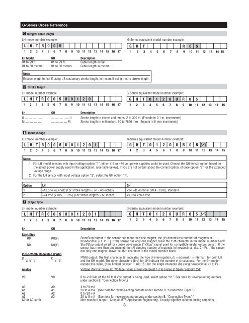
G-<strong>Series</strong> <strong>Cross</strong> <strong>Reference</strong>C Integral cable lengthLH model number example:L H T R 0 0 51 2 3 4 5 6 7 8 9 10 11 12 13 14 15 16 17G-<strong>Series</strong> equivalent model number example:G H T R 0 51 2 3 4 5 6 7 8 9 10 11 12 13 14 15LH <strong>Model</strong> <strong>GH</strong> Description01 to 99 ft. 01 to 99 ft. Cable length in feet01 to 30 meters 01 to 30 meters Cable length in metersNote:Encode length in feet if using US customary stroke length, in meters if using metric stroke length.D Stroke lengthLH model number example:L H T R 0 0 5 U 0 1 2 01 2 3 4 5 6 7 8 9 10 11 12 13 14 15 16 17G-<strong>Series</strong> equivalent model number example:G H T 0 1 2 0 U R 0 51 2 3 4 5 6 7 8 9 10 11 12 13 14 15LH <strong>GH</strong> DescriptionU — — — . — — — — . — U Stroke length in inches and tenths, 2 to 300 in. (Encode in 0.1 in. increments)M — — — — — — — — M Stroke length in millimeters, 50 to 7620 mm. (Encode in 5 mm increments)E Input voltageLH model number example:L H T R 0 0 5 U 0 1 2 0 11 2 3 4 5 6 7 8 9 10 11 12 13 14 15 16 17G-<strong>Series</strong> equivalent model number example:G H T 0 1 2 0 U R 0 5 1 21 2 3 4 5 6 7 8 9 10 11 12 13 14 15Notes:1. For LH model sensors with input voltage option “1”, either +15 or +24 volt power supplies could be used. Choose the <strong>GH</strong> sensor option based onthe actual power supply used in the application, (see table below). If you are not certain about the correct option, choose option “2” for the extendedvoltage range.2. For the LH sensor with input voltage option “2”, select the <strong>GH</strong> option “1”.Option LH <strong>GH</strong>1 +13.5 to 26.4 Vdc (For stroke lengths < or = 60 inches) +24 Vdc nominal (20.4 - 28.8), standard2 +24 Vdc (+10%, - 10%) (For stroke lengths > 60 inches) +9.0 to +28.8 VdcF Output typeLH model number example:L H T R 0 0 5 U 0 1 2 0 11 2 3 4 5 6 7 8 9 10 11 12 13 14 15 16 17G-<strong>Series</strong> equivalent model number example:G H T 0 1 2 0 U R 0 5 1 21 2 3 4 5 6 7 8 9 10 11 12 13 14 15LH <strong>GH</strong> DescriptionStart/StopR0 R0(#) Start/Stop output. If the sensor has more than one magnet, the (#) denotes the number of magnets inhexadecimal, (i.e. 2 - F). If the sensor has only one magnet, leave the 15th character in the model number blank.N0 N0(#) Start/Stop output wired for square wave neuter (“+Stop” signal used for compatible neuter output pulse). If thesensor has more than one magnet, the (#) denotes number of magnets in hexadecimal, (i.e. 2 - F). If the sensorhas only one magnet, leave the 15th character in the model number blank.Pulse-Width Modulated (PWM)D — — —a b cD — —a bPWM output. The first character (a) indicates the type of interrogation, (E = external, I = internal), for both LHand the <strong>GH</strong> model. The other characters (b-c) for LH indicate the number of circulations. For the <strong>GH</strong> modelencode this value, (now limited between 1 and 15), for the single character (b) using hexadecimal, (1 to F).Analog Voltage (format below is: “Voltage [value at Null (Setpoint 1)] to [value at Span (Setpoint 2)]”V0 V0 0 to +10 Vdc (If the 10 to 0 Vdc output is being used, select option “V1”. See note for reverse-acting outputsunder section B, “Connection Type”.)A0 A0 4 to 20 mAA1 A1 20 to 4 mA (See note for reverse-acting outputs under section B, “Connection Types”.)A2 A2 0 to 20 mAA3 A3 20 to 0 mA (See note for reverse-acting outputs under section B, “Connection Types”.)C0 or CC suffixNon-standard output. Consult <strong>MTS</strong> Application Engineering. Usually signifies custom analog setpoints.3