

G-Series Model GH Cross Reference - MTS Sensors
G-Series Model GH Cross Reference - MTS Sensors
G-Series Model GH Cross Reference - MTS Sensors

Create successful ePaper yourself
Turn your PDF publications into a flip-book with our unique Google optimized e-Paper software.
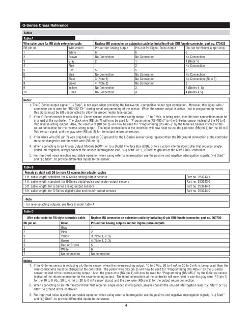
G-<strong>Series</strong> <strong>Cross</strong> <strong>Reference</strong>TablesTable AWire color code for RB style extension cable Replace RB connector on extension cable by Installing 6-pin DIN female connector, part no. 370423RB pin no. Wire colors Pin-out for Analog output Pin-out for Digital-Pulse output Pin-out for Neuter output only1 White 6 6 62 Brown No Connection No Connection No Connection3 Gray 2 1 1 (Note 1)4 Pink 1 2 No Connection5 Red 5 5 56 Blue No Connection No Connection No Connection7 Black 3 (Note 2) No Connection No Connection (Note 3)8 Violet 4 (Note 2) No Connection 29 Yellow No Connection 3 3 (Notes 4, 5)10 Green No Connection 4 4 (Notes 4,5)Notes:1. The G-<strong>Series</strong> output signal, “(-) Stop”, is not used when providing the backwards –compatible neuter type connection. However, this signal wire /connector pin is used for “RS-422 TX-“ during serial programming of the sensor. When the sensor output is active, (not in programming mode),this signal must be left unconnected to allow the proper neuter type output.2. If the G-<strong>Series</strong> sensor is replacing a L-<strong>Series</strong> sensor where the reverse-acting output, 10 to 0 Vdc, is being used, then the wire connections must bechanged at the controller. The black wire (RB pin 7) will now be used for “Programming (RS-485+)” by the G-<strong>Series</strong> sensor instead of the 10 to 0Vdc reverse-acting output. Also, the violet wire (RB pin 8) will now be used for “Programming (RS-485-)” by the G-<strong>Series</strong> sensor instead of thereturn connection for the reverse-acting output. The input connections at the controller will now need to use the pink wire (RB pin 4) for the 10 to 0Vdc sensor signal, and the gray wire (RB pin 3) for the output return connection.3. If the black wire (RB pin 7) was originally used as DC ground for the L-<strong>Series</strong> sensor being replaced then the DC ground connection at the controllermust be changed to use the white wire (RB pin 1).4. When connecting to an Analog Output Module (AOM), or to a Digital Interface Box (DIB), or to a custom interface/controller that requires singleendedinterrogation, always connect the unused interrogation lead, “(+) Start” or “(-) Start” to ground at the AOM / DIB / controller.5. For improved noise rejection and stable operation when using external interrogation use the positive and negative interrogation signals, “(+) Start”and “(-) Start”, to provide differential inputs to the sensor.Table BFemale straight exit D6 to male RB connection adapter cables1 ft. cable length, standard, for G-<strong>Series</strong> analog output sensors Part no. 253243-11 ft. cable length, standard, for G-<strong>Series</strong> digital-pulse and neuter output sensors Part no. 253243-25 ft. cable length, for G-<strong>Series</strong> analog output sensors Part no. 253244-15 ft. cable length, for G-<strong>Series</strong> digital-pulse and neuter output sensors Part no. 253244-2Note:For reverse-acting outputs, see Note 2 under Table A.Table CWire color code for RG style extension cable Replace RG connector on extension cable by installing 6-pin DIN female connector, part no. 560700RG pin no. Color Pin-out for Analog outputs and for Digital-pulse outputs1 Gray 12 Pink 23 Yellow 3 (Note 1, 2, 3)4 Green 4 (Note 1, 2, 3)5 Red or Brown 56 White 67 No connection No connectionNotes:1. If the G-<strong>Series</strong> sensor is replacing a L-<strong>Series</strong> sensor where the reverse-acting output, 10 to 0 Vdc, 20 to 4 mA or 20 to 0 mA, is being used, then thewire connections must be changed at the controller. The yellow wire (RG pin 3) will now be used for “Programming (RS-485+)” by the G-<strong>Series</strong>sensor instead of the reverse-acting output. Also, the green wire (RG pin 4) will now be used for “Programming (RS-485-)” by the G-<strong>Series</strong> sensorinstead of the return connection for the reverse-acting output. The input connections at the controller will now need to use the gray wire (RG pin 1)for the 10 to 0 Vdc, 20 to 4 mA or 20 to 0 mA sensor signal, and the pink wire (RG pin 2) for the output return connection.2. When connecting to an interface/controller that requires single-ended interrogation, always connect the unused interrogation lead, “(+) Start” or “(-)Start” to ground at the controller.3. For improved noise rejection and stable operation when using external interrogation use the positive and negative interrogation signals, “(+) Start”and “(-) Start”, to provide differential inputs to the sensor.4


