

G-Series Model GH Cross Reference - MTS Sensors
G-Series Model GH Cross Reference - MTS Sensors
G-Series Model GH Cross Reference - MTS Sensors

You also want an ePaper? Increase the reach of your titles
YUMPU automatically turns print PDFs into web optimized ePapers that Google loves.
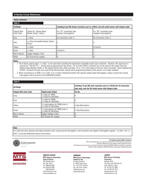
G-<strong>Series</strong> <strong>Cross</strong> <strong>Reference</strong>Tables continuedTable G<strong>GH</strong> <strong>Model</strong>Installing 6-pin MS female connector, part no. 370015, onto <strong>GH</strong> model sensor with integral cableIntegral WireColor CodeOutput for “Square Wave”Neuter (Using “+Stop”)For “R1” connection type:(positive interrogation)For “R2” connection type:(negative interrogation)Gray (-) Stop No Connection (note 1) No Connection (note 1)Pink(+) Stop (Compatible Neuter OutputPulse)CCYellow (+) Start E B (note 2)Green (-) Start B (note 2) ERed or Brown Supply Voltage (+Vdc) F FWhite DC Ground (for supply) B BNotes:1. The G-<strong>Series</strong> output signal, “(-) Stop”, is not used when providing the backwards-compatible neuter type connection. However, this signal wire isrequired for “RS-422 TX –“ during serial programming of the sensor. Pin A of the 370015 connector can not be used for this signal since theAnalog Output Module (AOM), or the Digital Interface Box (DIB), provides +12 to +14.5 volts output on this pin when connected. Upon installing the370015 connector the gray wire must be left disconnected, and the serial programming feature of the sensor is no longer available.2. When connecting to an AOM, or to a DIB, or to a custom interface/controller that requires single-ended interrogation, always connect the unusedinterrogation lead to ground at the AOM/DIB/Controller.Table H<strong>GH</strong> <strong>Model</strong>Installing 10-pin MS male connector, part no. 370160 (for R3 connectiontype only), onto the <strong>GH</strong> model sensor with integral cableIntegral Wire Color Code Digital pulse Output Pin No.Gray(-) Gate for PWM(-) Stop for Start/StopKPink(+) Gate for PWM(+) Stop for Start/StopGYellow(+) Interrogation for PWM (note 1)(+) Start for Start/StopE (See Note below)Green(-) Interrogation for PWM (note 1)(-) Start for Start/StopD (See Note below)Red or Brown Supply Voltage (+Vdc) HWhite DC Ground (for supply) ANote:For improved noise rejection and stable operation when using external interrogation, use the positive and negative interrogation signals, “(+) Start” and “(-)Start”, to provide differential inputs to the sensor.Part Number: 09-05 550956 Revision B<strong>MTS</strong> and Temposonics are registered trademarks of <strong>MTS</strong> Systems Corporation.All other trademarks are the property of their respective owners.All Temposonics sensors are covered by US patent number 5,545,984. Additional patents are pending.Printed in USA. Copyright © 2005 <strong>MTS</strong> Systems Corporation. All Rights Reserved.UNITED STATES<strong>MTS</strong> Systems Corporation<strong>Sensors</strong> Division3001 Sheldon DriveCary, NC 27513Tel: (800) 633-7609Fax: (919) 677-0200(800) 498-4442www.mtssensors.comsensorsinfo@mts.comGERMANY<strong>MTS</strong> Sensor TechnologieGmbH & Co. KGAuf dem Schüffel 9D - 58513 LüdenscheidTel: +49 / 23 51 / 95 87-0Fax: +49 / 23 51 / 56 491info@mtssensor.dewww.mtssensor.deJAPAN<strong>MTS</strong> <strong>Sensors</strong> TechnologyCorporationUshikubo Bldg.737 Aihara-cho, Machida-shiTokyo 194-0211, JapanTel: +81 (42) 775 / 3838Fax: +81 (42) 775 / 5512www.mtssensor.co.jpinfo@mtssensor.co.jp


