FD-5 - Tams
FD-5 - Tams
FD-5 - Tams

You also want an ePaper? Increase the reach of your titles
YUMPU automatically turns print PDFs into web optimized ePapers that Google loves.
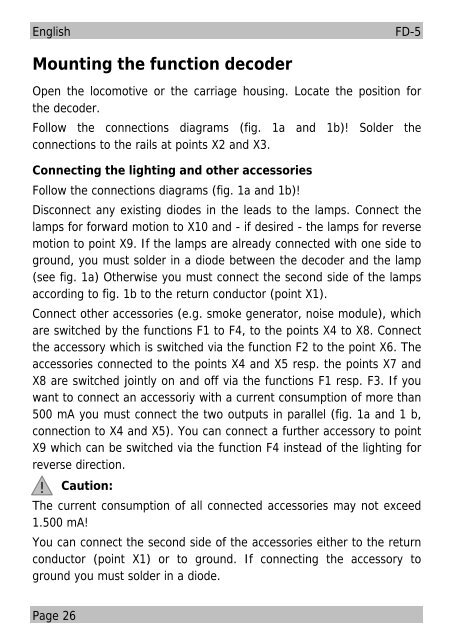
English<strong>FD</strong>-5Mounting the function decoderOpen the locomotive or the carriage housing. Locate the position forthe decoder.Follow the connections diagrams (fig. 1a and 1b)! Solder theconnections to the rails at points X2 and X3.Connecting the lighting and other accessoriesFollow the connections diagrams (fig. 1a and 1b)!Disconnect any existing diodes in the leads to the lamps. Connect thelamps for forward motion to X10 and - if desired - the lamps for reversemotion to point X9. If the lamps are already connected with one side toground, you must solder in a diode between the decoder and the lamp(see fig. 1a) Otherwise you must connect the second side of the lampsaccording to fig. 1b to the return conductor (point X1).Connect other accessories (e.g. smoke generator, noise module), whichare switched by the functions F1 to F4, to the points X4 to X8. Connectthe accessory which is switched via the function F2 to the point X6. Theaccessories connected to the points X4 and X5 resp. the points X7 andX8 are switched jointly on and off via the functions F1 resp. F3. If youwant to connect an accessoriy with a current consumption of more than500 mA you must connect the two outputs in parallel (fig. 1a and 1 b,connection to X4 and X5). You can connect a further accessory to pointX9 which can be switched via the function F4 instead of the lighting forreverse direction.! Caution:The current consumption of all connected accessories may not exceed1.500 mA!You can connect the second side of the accessories either to the returnconductor (point X1) or to ground. If connecting the accessory toground you must solder in a diode.Page 26