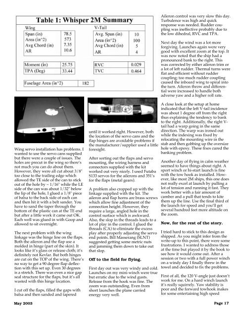
Hobby Lobby’s “WHISPER”2 Meter SailplaneEver since Mark LeVoe stoppedmaking the 2M Super-V, I’ve beenlooking for a good 2M sailplane. Smallfields, convenient transport, etc., allmake the 2M size something thatwould work well for some flying at theend of the work day. Hobby Lobby’s2M WHISPER sailplane looked like ithad some very interesting design ideasso we decided to give it a shot.Construction of the wing is a bitdifferent. Although it’s a hollow corewith a beautiful finish, the skins are abalsa laminate (glass/balsa/glass).Compression and flex strength seemvery good with this architecture.The wing itself is a double taper withsmall reverse Hoerner tips. The airfoilis reported to be a SD7037 and thatappears to be accurate. The finish isvery well done with the color featheringfrom yellow to red at the tips. Thelower surface is solid red withrounded cutouts for the servo cans(supplied with the kit). These areplaced inboard of the respectivecontrol surface.A wiring harness with Deans connectors(4 pin) is supplied along withhorns and linkage for conventionalservo installation. The wing also hascut outs for tubes for ballast (notsupplied) located near the CG. Thewing rod is straight with a slight angleto the wing tubes to provide a verymodest dihedral angle (about 3degrees).The fuselage is glass with the colorapplied in the mold. Although this isbe<strong>com</strong>ing more <strong>com</strong>mon for kits, I’mstill impressed with the quality anddurability of the surface finish producedby this technique. There are acouple of carbon strips along the baseof the fuselage which extend to the tail(on the interior surface). The wingroots are square to the wings with abrass tube through the fuselage for thewing rod and two indexing holes nearPage 16TECH TOPICSDave RegisterBartlesville, Oklahomaregdave@aol.<strong>com</strong>the LE and TE to align the wingmount.The servo cutout in the fuselage isalready done and only requires a littlereinforcing ply or basswood to drop inyour servos. Metal pushrods arealready installed with a screw fittingsoldered on the servo end for theclevis. Mine had a cold solder joint onone fitting which was easy to fix with alow wattage iron. Ample space isavailable ahead of the servos for a500mAh battery. A <strong>com</strong>pact 7 channelRx goes at the aft end of the servos.A nice feature in the fuselage is asealed area in the nose (ahead of thebattery). This can be drilled from thetop and lead shot added to get thebalance just right. After balancing,simply tape over the hole and you’redone.Final note on the fuselage, the towhook is pre-installed. The location isahead of the CG on about a 45 degreeangle which is very conservative for awinch launch.The WHISPER V-tails are built upgeodesic structure. These are precovered,requiring only that the controlsurface be taped and the linkageattached. The V-mount uses two metalrods at the root of the tail that areinserted in metal tubes in the fuselage.The tubes are staggered so the onesfrom either side won’t intersect. TheWHISPER V-tail included angle is 120degrees.A <strong>com</strong>plete hardware set came withthe kit: Hitec servo cans, threaded postlinkages for the wings, angled V-connector for the tail, etc.Since this is the Tech Topics guy, let’stake a look at some of the designnumbers. I’ve captured a few measurementsin Table 1 and calculated someof the associated design coefficients aswell.The first thing to note is that thevolume coefficient for the equivalenthorizontal surface (TVC) is in the midrangeof what I like, while the verticalvolume coefficient (RVC) is pretty low.I also note that the dihedral angle isvery shallow which may provideissues with yaw and roll stability. Withthe large included V-angle and the lowwing dihedral, this could be a problemfor yaw-roll response as well as rollstability while cruising betweenthermals.The wing planform <strong>com</strong>es close to theScheumann ellipse calculation done inthis column a couple of years ago. Itgives a good approximation to anelliptical distribution, which can beconfirmed by running the planform inthe Lift-Roll spreadsheet. Where thereis a discrepancy, the tips are a bitwider than elliptical. As we discusseda few columns ago, this is an appropriatedirection for both Re correctionsand to minimize tip stalls.One final note, the numbers alsoindicate that the tailplane angle is low.This simply means that the distancebetween quarter-chord of the wing andquarter-chord of the tail is a bit shorterthan a typical 2M design. Coupledwith the low RVC, this ship could beboth yaw and pitch sensitive if nottrimmed carefully.There’s not much to say about theequipment installation in the fuselage.I used a couple of S133 servos (Futaba)and they were very tight on the servoarm length. I’d re<strong>com</strong>mend a smallerservo. The HS80/85 and JR341/351would also be tight on the arms soyou’re either going to have to installthese with care or go to an S90, HS55,CS21 or similar size. Since this is a 2MI’d re<strong>com</strong>mend the higher torque gearsets for the CS21.Battery and Rx in the fuselage arestraightforward. A trick learned yearsago is to wrap a piece of electrical tapearound your battery after installation.There’s no way it can inadvertentlyexit the aircraft other than a fatalinteraction with the ground. The Rxused was a standard Futaba 7 channel.R/C Soaring Digest
Aileron control was very slow this day.Turbulence was high and quickresponse was needed. Rudder couplingwas ineffective probably due tothe low dihedral, RVC and TPA.Next day the wind was a lot moreforgiving. Launches again were verygood with excellent zoom at the top. Itwas now noted that the ship had apronounced bank to the right. Thiswas corrected by either aileron trim ora lot of left rudder. Thermal turns wereflat and efficient without ruddercoupling; too much rudder couplingcaused the inboard wing to spiral intothe turn. Aileron throw and differentialwere increased to handle bothadverse yaw and a higher roll rate.Wing servo installation has problems. Iwanted to use the servo cans suppliedbut there were a couple of issues. Theholes are precut in the wing so there’snot much you can do about them.However, they were all cut about 3/8"too close to the trailing edge whichallowed the TE side of the can to stickout of the hole by ~ 1/16" while the LEside of the can was about 1/32" belowthe lip of the hole, I glued a 1/8" pieceof balsa to the back side of each canand then hit it with a belt sander. Youhave to sand the taper through thebottom of the plastic can at the TE endbut after a little work it came out OK.Each well was glued in with Goop andallowed to sit overnight.The next problem with the winglinkage was the hinge line on the flaps.Both the aileron and the flap use amolded in hinge (part of the skin). Itlooks like it’s glass or release cloth; it’sdefinitely not Kevlar. But both hingesare cut on the TOP of the wing. There’sno way to get a 90 degree flap deflectionwith this set up. Even 30 degreesis a stretch. There was even a nice gapseal structure for the flaps, but it’s allwasted with this hinge location.I cut off the flaps, filled the gaps withbalsa and then sanded and tapered<strong>May</strong> 2003until it worked right. However, boththe location of the servo cans and theflap hinges are avoidable problems ifthe manufacturer/supplier used a littleforesight.After sorting out the flaps and servomounting, the wiring harness andconnectors supplied with the kitworked out very nicely. I used FutabaS133 servos for the ailerons and 351’sfor the flaps (metal gears).A problem also cropped up with thelinkage supplied with the kit. Theaileron and flap horns are brass screwswhich allow fine adjustment of theconnection height. However, theyrequire a large, angled hole in thecontrol surface which is awkward.Also, the slop in the threads leads to alot of play in the control. I glued thethreads (CA) to eliminate the excessplay after properly adjusting the servoend points. Bill Masserang (SLNT)suggested getting some metric nutsand jamming them down to take outthat slop.Off to the field for flying.First day out was very windy and cold.Launches on my mini-winch were truebut erratic due to the wind gusts.Release from the hook was fine. Thezoom was outstanding. Even fromshort launches the plane carriedenergy very well.A close look at the setup at homeindicated that the left V-tail incidencewas about 1 degree off from the rightthus explaining the tendency to bankto the right. Additionally, the right V-tail had a warp going in the samedirection. The warp was ironed outwhile the indexing was fixed byrelocating the mounting wire in thestab and then gobbing up the oversizehole with epoxy. These fixes cured thebanking problem.Another day of flying in calm weatherseemed to have things about right. Asport winch or hi-start launch is finewith the tow hook as installed. However,like most 2M ships, this one doesnot really excel at launch by pulling alot of tension and running it fast. Theywork better with a fair amount ofcamber and a pull that tends to kitethem up the line. Use the final third ofthe launch for speed and you’ll getseveral hundred feet more altitude onthe zoom.Now, for the rest of the story.I tried hard to stick to this design asshipped. As you might infer from thewrite-up to this point, there were somefrustrations. I wanted to address thoseat the time but played it by the book tosee how it would <strong>com</strong>e out. After asession or two with a full power winchon a windy day I finally threw in thetowel and decided to fix the problems.First of all, the 120 V-angle just doesn’twork for me. On a hard winch launchit’s really squirrely. Yaw stability ispoor and the forward towhook makesfor some entertaining high speedPage 17