
You also want an ePaper? Increase the reach of your titles
YUMPU automatically turns print PDFs into web optimized ePapers that Google loves.
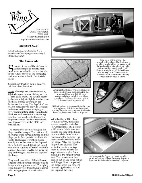
squared@appleisp.nethttp://www.b2streamlines.<strong>com</strong>Blackbird XC.3Construction of our Blackbird XC is<strong>com</strong>plete and test flying was successful.Read all about it!Page 6The frameworkSeveral pictures of the airframe invarious stages of constructionwere included in the last installment.A few photos of the <strong>com</strong>pletedairframe are included in this installment.Several construction points deserveadditional explanation.Flaps: The flaps are constructed of 1/8th inch square spruce sticks glued to1/16th balsa sheet. The outside rectangularframe is just slightly smaller thanthe balsa framed opening in thebottom of the wing. The flap “ribs” areplaced diagonally to provide torsionalresistance and prevent warping. Aplywood mounting plate was added atthe inner end to serve as a mountingpoint for the short control horn. Theupper surface of the truss frameworkwas then covered with 1/16th inchbalsa sheet.The method we used for hinging theflaps is rather unique. The bottoms ofthe wings were turned upward and theflaps put in final position within theirwells. The hinges were then placedevenly across the front of the flap andtheir outlines traced. Using the tracedoutlines as a guide, a Dremel tool witha router base was used to cut away theflap and wing material to the depth ofthe hinge.Very small quantities of thin oil wereapplied to the bearing surfaces of eachhinge and the pin removed. The lightlyoiled hinges were then strung togetherwith a single piece of music wire.A typical flap hinge. The nylon hinge isinset into the balsa sheet covering thewing and flap, and 1/64th inchcontoured plywood plates are thenglued over the hinges to support theUltracoat covering material.(R) Molten lead was poured into the nosethrough use of aluminum dams andtipping the sides at 45 degrees. Each sideholds slightly more than a half pound.With the flap still in placewithin its cavity, the hingeswere arranged in their shallowdepressions. The point ofa #11 X-Acto blade was usedto hold one side of the hingein place while thin CA wasrun around the outline. Thispermanently fixed one half ofthe hinge. All of the flap sidehinges were glued in firstwhile the music wire keptthem all in line and the oilkept extraneous glue fromsticking to the hinge bearingarea. The process was thencarried out on the other half ofeach hinge. Once <strong>com</strong>pleted,the hinges were in a straightline and rigidly fixed to boththe flap and the wing.Side view of the nose of the<strong>com</strong>pleted fuselage. The lead noseweights closely follow the contour ofthe keel and the triangle stock rightin front of the battery pack. Leadsheet is also placed on both sides ofthe battery pack. The receiver isplaced in foam between the batterypack and the rudder servo.A closeup of the flap servo location whichprovides an idea of how the control systemoperates. Full flap deflection is 45 degrees.R/C Soaring Digest