Repairs to Scherzer Rolling Lift Bridge - Heavy Movable Structures ...
Repairs to Scherzer Rolling Lift Bridge - Heavy Movable Structures ...
Repairs to Scherzer Rolling Lift Bridge - Heavy Movable Structures ...
Create successful ePaper yourself
Turn your PDF publications into a flip-book with our unique Google optimized e-Paper software.
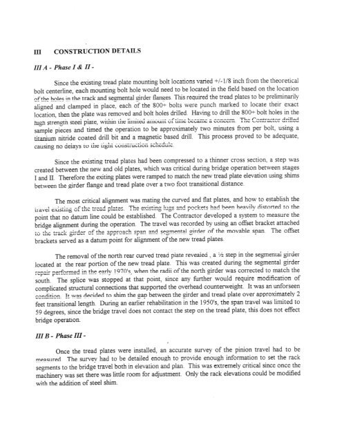
111 A - Phase I & II-Since the existing tread plate mounting bolt locations varied +/-I18 inch from the theoreticalbolt centerline, each mounting bolt hole would need <strong>to</strong> be located in the field based on the locationof the holes in the track and segmental girder flanges. This required the tread plates <strong>to</strong> be preliminarilyaligned and clamped in place, each of the 8001 bolts were punch marked <strong>to</strong> locate their exactlocation, then the plate was removed and bolt holes drilled Having <strong>to</strong> drill the 8001- bolt holes in thehigh strength steel plate, within the limited amount of time became a concern The Contrac<strong>to</strong>r drilledsample pieces and timed the operation <strong>to</strong> be approximately two minutes from per bolt, using atitanium nitride coated drill bit and a magnetic based drill. This process proved <strong>to</strong> be adequate,causing no delays <strong>to</strong> the tight construction scheduleSince the existing tread plates had been compressed <strong>to</strong> a thinner cross section, a step wascreated between the new and old plates, which was critical during bridge operation between stagesI and 11. Therefore the exiting plates were ramped <strong>to</strong> match the new tread plate elevation using shimsbetween the girder flange and tread plate over a two foot transitional distance.The most critical alignment was mating the curved and flat plates, and how <strong>to</strong> establish thetravel existing of the tread plates. The existing lugs and pockets had been heavily dis<strong>to</strong>rted <strong>to</strong> thepoint that no datum line could be established. The Contrac<strong>to</strong>r developed a system <strong>to</strong> measure thebridge alignment during the operation. The travel was recorded by using an offset bracket attached<strong>to</strong> the track girder of the approach span and segmental girder of the movable span. The offsetbrackets served as a datum point for alignment of the new tread plates.The removal of the north rear curved tread plate revealed , a '/z step in the se,gnental girderlocated at the rear portion of the new tread plate. This was created during the segmental girderrepair performed in the early 197O9s, when the radii of the north girder was corrected <strong>to</strong> match thesouth. The splice was s<strong>to</strong>pped at that point, since any hrther would require modification ofcomplicated structural connections that supported the overhead counterweight. It was an unforseencondition. It was decided <strong>to</strong> shm the gap between the girder and tread plate over approximately 2feet transitional length. During an earlier rehabilitation in the 1950ts, the span travel was limited <strong>to</strong>59 degrees, since the bridge travel does not contact the step on the tread plate, this does not effectbridge operation.111 B - Phase III-Once the tread plates were installed, an accurate survey of the pinion travel had <strong>to</strong> bemeasured. The survey had <strong>to</strong> be detailed enough <strong>to</strong> provide enough information <strong>to</strong> set the racksegments <strong>to</strong> the bridge travel both in elevation and plan. This was extremely critical since once themachinery was set there was little room for adjustment. Only the rack elevations could be modifiedwith the addition of steel shim.


