
Create successful ePaper yourself
Turn your PDF publications into a flip-book with our unique Google optimized e-Paper software.
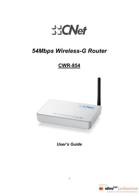
54Mbps <strong>Wireless</strong>-G <strong>Router</strong>CWR-854User’s Guide1
.......................................................................................................................................... 3............................................................................................................... 3 ................................................................................................ 3CHAPTER-1 INTRODUCTION................................................................................................................. 41.1 PACKAGE CONTENT .................................................................................................................... 41.2 SPECIFICATION .................................................................................................................................... 51.3 FEATURES............................................................................................................................................ 61.4 LED INDICATOR................................................................................................................................... 71.5 REAL PANEL DESCRIPTION................................................................................................................. 8CHAPTER-2 INSTALLATION................................................................................................................... 92.1 HARDWARE INSTALLATION................................................................................................................... 92.2 PREPARING THE NETWORKING ......................................................................................................... 102.3 COLLECTING ISP INFORMATION........................................................................................................ 102.4 CONFIGURING WINDOWS FOR IP NETWORKING............................................................................... 10CHAPTER-3 WEB CONFIGURATION............................................................................................... 163.1 SETUP WIZARD.................................................................................................................................. 163.1.1.Operation Mode .................................................................................................................... 173.1.2 Time Zone Settings .............................................................................................................. 183.1.3 LAN Interface Setup............................................................................................................. 193.1.4 WAN Interface Setup............................................................................................................ 203.1.5 <strong>Wireless</strong> Basic Settings ...................................................................................................... 213.1.6 <strong>Wireless</strong> Security Setup ..................................................................................................... 223.2 OPERATION MODE............................................................................................................................. 233.3 WIRELESS.......................................................................................................................................... 243.3.1 Basic Settings ....................................................................................................................... 243.3.2 <strong>Wireless</strong> Advanced Settings.............................................................................................. 263.3.3 Security................................................................................................................................... 283.3.4 Access Control...................................................................................................................... 333.3.5 WDS Settings......................................................................................................................... 343.3.6 Site Survey ............................................................................................................................. 353.3.7 WPS.......................................................................................................................................... 363.4 TCP / IP SETTINGS ........................................................................................................................... 373.4.1 LAN Interface......................................................................................................................... 373.4.2 WAN Interface........................................................................................................................ 393.5 FIREWALL .......................................................................................................................................... 473.5.1 Port Filtering .......................................................................................................................... 473.5.2 IP Filtering .............................................................................................................................. 483.5.3 MAC Filtering......................................................................................................................... 493.5.4 Port Forwarding .................................................................................................................... 503.5.5 URL Filtering.......................................................................................................................... 513.5.6 DMZ .......................................................................................................................................... 523.6 MANAGEMENT ................................................................................................................................... 533.6.1 Status....................................................................................................................................... 533.6.2 Statistics ................................................................................................................................. 543.6.3 DDNS ....................................................................................................................................... 553.6.4 Time Zone Settings .............................................................................................................. 563.6.5 Denial of Service (DoS Prevention) ................................................................................. 573.6.6 Event Log................................................................................................................................ 583.6.7 Upgrade Firmware................................................................................................................ 593.6.8 Save / Reload Settings ........................................................................................................ 603.6.9 Password................................................................................................................................ 61APPENDIX A: TROUBLESHOOTING................................................................................................... 62APPENDIX B: FREQUENTLY ASKED QUESTIONS .......................................................................... 652
Following is the explanation of the picture. 3
Chapter-1 IntroductionThank you for choosing the <strong>CNet</strong> <strong>Wireless</strong> series product. CWR-854 is an ideal<strong>Wireless</strong>-G <strong>Router</strong> for the small office or home networking environments. SettingSOHO and enterprise standard for high performance, secure, manageable andreliable WLAN. CWR-854 is not only a <strong>Wireless</strong> <strong>Router</strong> but also supports APClient / Bridge and WDS (<strong>Wireless</strong> Distributed System) mode to satisfy all kinds ofthe application from different networking environment. The WPS (Wi-Fi ProtectedSetup) function could help you establish a wireless home network easily andsecurely.CWR-854 also provides step-by-step installation for both Internet setting as wellas LAN and <strong>Wireless</strong> connection. For <strong>Wireless</strong> security that the router supportsWEP, WPA and WPA2 (TKIP/AES), and CWR-854 also equipped with advancedMAC address, IP/Port Filtering and URL Filtering to safe and secure home oroffice network.This router can be easily configured without other utility install. You could justfollow this user manual to setup your <strong>Wireless</strong> Network with the embedded GUIbrowser.1.1 Package ContentThe package of CWR-854 includes the following items,1 x CWR-8541 x Power Adapter1 x Documentation CD1 x RJ-45 Cable Line1 x Detachable Antenna1 x Cradle1 x QIGNotes: If any of above items are missing, please contact with your supplier as soon aspossible.4
1.2 SpecificationStandardFrequency BandRadio TypeData Rate (<strong>Wireless</strong>)Access ProtocolNumber of Operation ChannelOperation ModeSecurityRF Output Power (Typical)SensitivityAntennaDimension (L x W x H)WeightOperation TemperatureStorage TemperatureHumidityConnectorPower requirementIEEE 802.11G/B2.400GHz ~ 2.484GHzIEEE 802.11g: OFDM (64-QAM, 16-QAM, QPSK, BPSK)IEEE 802.11b: DSSS (CCK/DQPSK/DBPSK)802.11g: 54 / 48 / 36 / 24 / 18 / 12 / 9 & 6Mbps802.11b: 11 / 5.5 / 2 & 1 Mbps with auto-rate fall backCSMA/CA2.412~2.462GHz (Canada, FCC) / 11 Channels2.412~2.484GHz (Japan, TELEC) / 14 Channels2.412~2.472GHz (Euro, ETSI) / 13 ChannelsAPAP Client (ad-hoc and infrastructure)ClientBridge (point-to-pint and point-to-multipoint)WDS (<strong>Wireless</strong> Description System)64/128bit WEPWPA (TKIP with IEEE 802.1x)WPA2 (AES with IEEE 802.1x)802.11g: up to 14 ± 1 dBm802.11b: up to 17 ± 1 dBm-68dBm @ 802.11g-80dBm @ 802.11bOne detachable 5dbi antenna165 x 118 x 27mm (6.49 x 4.65 x 1.06inch)245g0°C ~ 40°C (32 ~ 104F)-20°C ~ 60 °C (-4 ~ 140F)10% ~ 90% (Non-condensing)One antenna connectorOne RJ-45 port for WANFour RJ-45 LAN portsReset to default buttonWPS buttonPower jack12V DC, 1A5
1.3 Features 802.11b/g compliant with 54Mbps high-speed data rate Operation modes: AP, AP client, Client, Bridge, WDS DHCP Server/Client Four Ethernet ports for broadband sharing Virtual DMZ, Port Forwarding Dynamic DNS TCP/UDP/ICMP/ARP protocol stack Firewall, URL/IP/Port/MAC filtering <strong>Wireless</strong> users access control <strong>Wireless</strong> security – 64/128bit WEP, WPA/WPA2, 802.1x and 802.11i Support PPPoE, VPN pass-through with multiple sessions, PPTP and L2TP Universal Plug and Play, no complicated installation necessary Quick and easy setup with Web-based management utility Detachable antenna allows user to replace higher gain antenna Supports WPS, 64-bit and 128-bit WEP, WPA, WPA2 encryption/decryption6
1.4 LED IndicatorLED Indicator State DescriptionPOWER ON The WLAN Broadband <strong>Router</strong> is powered onOFFThe WLAN Broadband <strong>Router</strong> is powered offWLAN Flashing Data is transmitting or receiving on the antennaOFFNo data is transmitting or receiving on the antennaWAN Flashing Data is transmitting or receiving on the LAN interfaceONOFFPort linkedNo linkLAN 1~4 Flashing Data is transmitting or receiving on the WAN interfaceWPSONOFFONOFFPort linkedNo linkWPS function is waiting for the registration from clientsideWPS function is off7
1.5 Real Panel DescriptionInterfacesAntenna (Fixed / SMA) The <strong>Wireless</strong> LAN Antenna.ResetWPSLANWANPowerDescriptionPush continually the reset button 5 ~ 10 seconds to reset the configurationparameters to factory defaults.Push continually the WPS button 5 ~ 10 seconds to enable the WPS feature.The RJ-45 sockets allow LAN connection through Category 5 cables. Supportsauto-sensing on 10/100M speed and half / full duplex, and comply with IEEE 802.3/ 802.3u respectively.The RJ-45 socket allows WAN connection through a Category 5 cable. Supportsauto-sensing on 10/100M speed and half / full duplex, and comply with IEEE802.3/ 802.3u respectively.The power jack allows an external power supply connection.8
Chapter-2 Installation2.1 Hardware Installation1. Place the <strong>Wireless</strong> LAN Broadband <strong>Router</strong> to the best optimum transmission location.The best transmission location for your WLAN Broadband <strong>Router</strong> is usually at thegeographic center of your wireless network, with line of sign to all of your mobile stations.2. Connect the WAN port on the router to a Cable/DSL modem, Ethernet Server, orhub.3. Connect one or more client PCs to the LAN port(s).4. Connect the power adapter to the wall outlet and the power jack on the router.5. Turn your PCs on.9
2.2 Preparing the NetworkingThis chapter covers the things that need to be done before configuring the router. The first thing isto set all computers on the network for TCP/IP networking and also gather necessary informationfrom the Internet Service Provider (ISP).2.3 Collecting ISP InformationThe following information needs to be gathered from the ISP before configuring the router:IP Assignment from ISP: Are IPs assigned dynamically or you have a fixed IP address? If fixed,what are the IP address, Subnet Mask, Default Gateway as well as the DNS addresses for thisaccount?Connection Type: Is this a PPPoE or PPTP connection? If PPPoE, what are the username andpassword associated with this account? If PPTP, the server IP address as well as userauthentication information is required.Please contact your ISP if you’re not sure of the answers to these questions.2.4 Configuring Windows for IP NetworkingEach computer on the network and connecting to the router should be configured for TCP/IPnetworking. The router is by default a DHCP server and if you plan to use DHCP (recommended).Each computer must be configured to receive an IP address automatically. See the procedurebelow.If fixed IP addresses are to be used on the network, you’ll need to manually assign an IP addressto each computer and make sure that they are in the same subnet as the router. Refer to yourWindows documentation for instructions on IP assignment.To configure TCP/IP in Windows:Configuring Windows 98 and millennium PCs1. Click the Start button go to Settings and click on Control Panel. In Control Panel,double-click the Network icon.2. Under the Configuration tab, select the TCP/IP line for the applicable Ethernet adapter. Donot choose a TCP/IP entry whose name mentions DUN, PPPoE, VPN, or AOL. If the wordTCP/IP appears by itself, select that line. Click the Properties button.10
3. Click the IP Address tab. Select Obtain an IP address automatically.4. Now click the Gateway tab, and verify that the Installed Gateways field is Blank. Click theOK button.5. Click the OK button again. Windows may ask for original Windows installation CD oradditional files. Check for the files at c:\windows\options\cabs, or insert your WindowsCD-ROM into the CDROM drive and enter the correct file location, e.g., D:\win98, D:\win9x,etc. ( “D” is the drive letter of the CD-ROM drive).6. Windows may ask to restart the PC. Click the Yes button. If Windows does not prompt torestart, restart the computer anyway.11
Configuring Windows 2000 PCs1. Click the Start button go to Settings and click on Control Panel. In Control Panel,double-click the Network and Dial-up Connections icon.2. Select the Local Area Connection icon for the applicable Ethernet adapter (usually it is thefirst Local Area Connection listed). Double-click the Local Area Connection and Click theProperties button.3. Make sure the box next to Internet Protocol (TCP/IP) is checked. Highlight Internet Protocol(TCP/IP), and click the Properties button.12
4. Select Obtain an IP address automatically and click the OK button. Click the OK buttonagain to complete the PC configuration.5. Restart your computer.13
Configuring Windows XP PCsThe following instructions assume you are running Windows XP with the default interface (ControlPanel looks different then previous versions of Windows). If you are using the Classic View (whereicons and menus look similar to previous Windows versions), please follow the instructions forWindows 2000.1. Click the Start button and then the Control Panel icon. Click the Network and InternetConnections icon. Then click the Network Connections icon.2. Select the Local Area Connection icon for the applicable Ethernet adapter (usually it is thefirst Local Area Connection listed). Double-click the Local Area Connection and click theProperties button.3. Highlight Internet Protocol (TCP/IP), and click the Properties button.14
4. Select Obtain an IP address automatically and click OK. Click the OK button again tocomplete the PC configuration.Configuring Windows XP PCs15
Chapter-3Web ConfigurationThis chapter describes how to access the router through the web browser. Pleasebe noted that in order to access the router’s admin page, a computer must beconnected to one of the LAN ports on the router.The WLAN Broadband <strong>Router</strong> is delivered with the following factory defaultparameters on the Ethernet LAN interfaces.Default IP Address: 192.168.1.254Default IP subnet mask: 255.255.255.0WEB login User Name: WEB login Password: 3.1 Setup WizardAfter a successful log-in to the router, the setup page will be shown as the below picture.The router’s configuration menu provides a Setup Wizard for basic configuration of the router.For more advanced feature settings. Users have to choose different menu items, and then click“Next” to proceed with Setup Wizard.16
3.1.1.Operation ModeThis page followed by Setup Wizard page to define the operation mode. CWR-854 supports threekinds of operation mode for the different application and environment. CWR-854 can be presenteda NAT <strong>Router</strong>, Bridge or <strong>Wireless</strong> ISP Client.17
3.1.2 Time Zone SettingsUsers can synchronize the local clock on the router to an available NTP server (optional). Tocomplete this setting, enable NTP client update and select the correct Time Zone.Enable NTP client update: Enable time zone update functionTime Zone Select: Select the time zone this router is used in.NTP server: Select from the list of NTP servers by clicking the down arrow key ormanually enter time server IP address.Cancel: To skip the current settings and jump to the Setup Wizard page.Back: To skip the current settings and go back to the last page.Next: Go to the next page.After completing the time zone settings, click “Next” to proceed to the LAN Interface Setup page.18
3.1.3 LAN Interface SetupIn the LAN interface Setup page, users can change the LAN IP address and Subnet Mask of therouter. Most Users will not need to change these values.IP Address: Current IP address of the <strong>Wireless</strong>-G <strong>Router</strong>, not WAN IP address.Subnet Mask: Current subnet mask for the <strong>Wireless</strong>-G <strong>Router</strong>, not WAN subnetmask addressCancel: To skip the current settings and jump to the Setup Wizard page.Back: To skip the current settings and go back to the last page.Next: Go to the next page.After typing in the IP Address and Subnet Mask, click “Next” to move on the WAN interface setuppage.19
3.1.4 WAN Interface SetupIn this screen users must identify and configure the connection type used for connectingto their Internet Service Provider (ISP). WAN Access Type: CWR supports 4 kinds of access type to connect the ISP –Static IP, DHCP Client, PPPoE, PPTP. Cancel: To skip the current settings and jump to the Setup Wizard page. Back: To skip the current settings and go back to the last page. Next: Go to the next page.After all items are set, click “Next” to advance to the next screen, <strong>Wireless</strong> Basic Settings page.20
3.1.5 <strong>Wireless</strong> Basic SettingsIn the <strong>Wireless</strong> Basic Settings page, users can configure the operating “Band” and “Mode” as wellas “Network Type”, ” SSID”, “Channel Number” and if required MAC address cloning. Operating Band: 802.11B/G, 802.11G or 802.11B Operating Mode: AP, Client, WDS and AP+WDS. Network type: when operating mode is “Client” mode, users can select thenetwork type as “infrastructure” or “Ad-hoc”. SSID: The SSID differentiates one WLAN from another, therefore, all wirelessaccess points/routers and all wireless devices attempting to connect to a specificWLAN must use the same SSID. It is case-sensitive and must not exceed 32characters Channel Number: The number of channels supported depends on the region this<strong>Wireless</strong>-G <strong>Router</strong> is used in. All stations communicating with this <strong>Wireless</strong>-G<strong>Router</strong> must use the same channel. (Note: not supported in client mode) Enable Mac clone: when operating mode is “Client” and only one Ethernet clientexists, users can enable the Mac clone feature to easily connect to the wirelessstation. Cancel: To skip the current settings and jump to the Setup Wizard page. Next: Go to the next page. Back: To skip the current settings and go back to the last page.21
3.1.6 <strong>Wireless</strong> Security SetupThis page is used to configure wireless security. CWR-854 could support WEP, WPA and WPA2Encryption key. Those encryption methods could prevent any unauthorized access to yourwireless network.After all items are set, click on “Finished” button to save all the parameters you have set, and therouter will reboot automatically.22
3.2 Operation ModeThis page is used to configure which mode wireless broadband router acts. Gateway: Traditional gateway configuration. It always connects to the Internet viaADSL/Cable Modem. LAN interface, WAN interface, <strong>Wireless</strong> interface, NAT andFirewall modules are applied to this mode Bridge: Each interface (LAN, WAN and <strong>Wireless</strong>) regards as bridge. NAT,Firewall and all router's functions are not supported <strong>Wireless</strong> ISP: Switch <strong>Wireless</strong> interface to be switched to the WAN port and allEthernet ports in bridge mode. Apply Changes: Click the Apply Changes button to complete the newconfiguration setting. Reset: Click the Reset button to abort change and recover the previousconfiguration setting.23
3.3 <strong>Wireless</strong>3.3.1 Basic SettingsThe <strong>Wireless</strong> Basic Settings include Band, Mode, SSID, Channel Number and other wirelesssettings. Disable <strong>Wireless</strong> LAN Interface: The wireless interface will be disabled whenchecked. Band: This <strong>Wireless</strong>-G <strong>Router</strong> can support three RF band: 802.11B/G, 802.11Gand 802.11B. Mode: This <strong>Wireless</strong>-G <strong>Router</strong> supports four operating modes: AP, client, WDS,and AP+WDS. Network Type: In Client mode, users can select the network type as“Infrastructure” or “Ad-hoc”. Infrastructure mode allows the PCs or small LAN ableto access the network via the Access Point. Ad-hoc mode is a station alone withother wireless station and can establish a small wireless network with connect toan Access Point. SSID: The SSID differentiates one WLAN from another, therefore, all wirelessaccess points/routers and all wireless devices attempting to connect to a specificWLAN must use the same SSID. It is case-sensitive and must not exceed 32characters. Channel Number: The number of channels supported depends on the region<strong>Wireless</strong>-G <strong>Router</strong> is used in. All stations communicating with this <strong>Wireless</strong>-G<strong>Router</strong> must be on the same channel. Associated Clients: When clicked on “Show Active Client” button, all associatedwireless clients will be shown. The feature is only available in AP and AP+WDSmodes. Enable Mac clone: When operating mode is Client mode and only one Ethernetclient exists, users can enable this Mac clone feature to connect with wirelessstation easily. Enable Universal Repeater Mode: The router can act as Station and AP at thesame time. It can use Station function to connect to a Root AP and use APfunction to service all wireless stations within its coverage. SSID for Extended Interface: The SSID could be defined for the wireless LAN24
user when the router connect to a Root AP (When Universal Repeater Mode beenabled)Apply Changes: Click on “Apply Changes” to save changes and logout.Reset: Click on “Reset” to undo your changes.25
3.3.2 <strong>Wireless</strong> Advanced SettingsIn Advanced Settings page, more 802.11 related parameters are tunable.Authentication Type: The router supports three kinds of the authentication types-Open System, Shared Key, and Auto.Fragment Threshold: Fragmentation mechanism is used for improving theefficiency when traffic is high in the wireless network. If a wireless client oftentransmits large files, you can enter new Fragment Threshold value to split thepacket. The value can be set from 256 to 2346. The default value is 2346.RTS Threshold: RTS Threshold is a mechanism implemented to prevent the“Hidden Node” problem. “Hidden Node” is a situation in which two stations arewithin range of the same wireless access point/router, but are not within range ofeach other. Therefore, they are hidden nodes for each other. When a station startsdata transmission with the <strong>Wireless</strong>-G <strong>Router</strong>, it might not notice that the otherstation is already using the wireless medium. When these two stations send dataat the same time, they might collide when simultaneously arriving at the<strong>Wireless</strong>-G <strong>Router</strong>. The collision will most certainly result in loss of messages ofboth stations. If the “Hidden Node” problem is an issue, please specify the packetsize. The RTS mechanism will be activated if the data size exceeds the value youset. The default value is 2347.Beacon Interval: Beacon interval is the amount of time between beacontransmissions. Before a station enters power save mode, the station needs thebeacon interval to know when to wake up to receive the beacon (and learnwhether there are buffered frames at the wireless router).Data Rate: By default, it selects the highest rate for transmission.Preamble Type: A preamble is a signal used in wireless environments tosynchronize transmit timings including Synchronization and Start Frame Delimiter.In a “noisy” network environment, Preamble Type should be set to Long. TheShort Preamble is intended for applications where minimum overhead and26
maximum performance is desired. Broadcast SSID: When enabled allows all wireless stations to detect the SSID ofthis wireless router. IAPP: The Inter-Access Point Protocol (IAPP) can extend multi-vendorinteroperability to the roaming function. 802.11g Protection: Is used to prevent packet collision and increaseperformance in wireless networks with both 802.11b (using CCK modulation) and802.11g (using OFDM modulation) devices. WMM: The short of Wi-Fi Multi-Media. It will enhance the data transferperformance of multimedia content when they are being transferred over wirelessnetwork. If you do not know what it is / not sure if you need it. It’s safe to set thisoption to “Enable”, however, default value is “Disable”. RF Output Power: Output power can be set of wireless radio. Unless you areusing this wireless router in a really big space. You may not have to set outputpower to 100%. This will enhance security. Turbo Mode: The data rate will up to 72Mbps when the turbo mode is enabled.Please be noted the turbo mode might have compatibility issue when be usedwithout Realtek solution. Apply Changes: Click on “Apply Changes” to save the setting. Reset: Click on “Reset” button to undo your changes.27
3.3.3 SecurityHere users define the security type and level of the wireless network. Selecting different methodsprovides different levels of security. Please note that using any encryption may cause asignificant degradation of data throughput on the wireless link. There are five Encryptiontypes supported: “None”, “WEP”, “WPA (TKIP)”, ”WPA2(AES)”, and “WPA2 Mixed”.No Encryption Used Encryption: “None” means no encryption used. Users can enable 802.1xAuthentication and enter the RADIUS server parameters – port, IP address andPassword. Use 802.1x Authentication: Is a port access protocol for protecting networks viaauthentication. If wireless user is authenticated (via 802.1x), a virtual port isopened on the router/access point allowing for communication. If authenticationfails, the router/access point will deny access to the user. Authentication RADIUS Server: RADIUS is the Remote Access Dial-In UserService, an Authorization, Authentication, and Accounting (AAA) client -serverprotocol, which is used when a AAA dial-up client logs in or out of a NetworkAccess Server. Typically, a RADIUS server is used by Internet Service Providers(ISP) to perform AAA tasks. AAA phases are described as follows: Authentication phase: Verifies a user name and password against a localdatabase. After the credentials are verified, the authorization processbegins. Authorization phase: Determines whether a request is allowed access to aresource. An IP address is assigned for the Dial-Up client. Accounting phase: Collects information on resource usage for the purposeof trend analysis, auditing, session time billing, or cost allocation.Users must enter RADIUS Server’s Port number, IP address and Password. Apply Changes: Click on “Apply Changes” to save the setting. Reset: Click on “Reset” button to undo your changes.28
WEP EncryptionEncryption: “WEP” (Wired Equivalent Privacy) encryption type.Set WEP Key: Only active when “Use 802.1x Authentication” is not selected.Use 802.1x Authentication: When this feature is enabled, users need to enterparameters of the “RADIUS Server” and select the encryption key length to be“WEP 64bits” or “WEP 128bits”.Authentication RADIUS Server: RADIUS Server’s Port number, IP addressand Password.Apply Changes: Click on “Apply Changes” to save the setting.Reset: Click on “Reset” button to undo your changes.When “Set WEP Key” is selected, the <strong>Wireless</strong> WEP Key Setup window will display asbelow:29
- Key Length: Choose either 64-bit or 128-bit.- Key Format: Select Hexadecimal or ASCII .- Default Tx Key: Select the default encryption Key (Key1 to Key4) beingtransmitted.- Encryption Key 1: enter any key code for Encryption Key 1.- Encryption Key 2: enter any key code for Encryption Key 2.- Encryption Key 3: enter any key code for Encryption Key 3.- Encryption Key 4: enter any key code for Encryption Key 4.- Apply Changes: Click on “Apply Changes” to save settings.- Close: To close this window.- Reset: Click on “Reset” button to undo your changes.- Help: To request help information.WEP encryption key (secret key) length:FormatLength64-bit128-bitASCII 5 characters 13 charactersHEX 10 hexadecimal codes 26 hexadecimal codesWPA / WPA2 Encryption30
- Encryption: “WPA” stands for Wi-Fi Protected Access. There are three encryptionmodes – TKIP, AES and Mixed. TKIP: Temporal Key Integrity Protocol. AES: Advanced Encryption Standard. Mixed: WPA2 Mixed mode operation permits the coexistence of WPA andWPA2 clients on a common SSID. WPA2 Mixed Mode is a Wi-Fi Certifiedfeature. During WPA2 Mixed Mode, the <strong>Wireless</strong>-G <strong>Router</strong> advertises theencryption ciphers (TKIP, CCMP, other) that are available for use. The clientselects the encryption cipher it likes to use and the selected cipher is usedfor encryption between the client and <strong>Wireless</strong>-G <strong>Router</strong>.31
WPA Authentication Mode: There are two modes of WPA authentication -Enterprise (RADIUS) and Personal (Pre-Shared Key). WPA Cipher Suite: There are two modes could be chose – TKIP and AES ( WPA2 Cipher Suite: There are two method could be chose – TKIP and AES RADIUS Server: When user chooses RADIUS authentication, there are threeparameters for the RADIUS server to be set – Port, IP address and Password. Pre-Shared Key: When user chooses Pre-Shared Key authentication, there aretwo types of input format – ASCII and Hex. Enable Pre-Authentication: Only valid when WPA2(AES) and WPA2 (Mixedmode) encryption is selected. When user chooses Enterprise (RADIUS)authentication, this feature allows the radius server to do the pre-authenticationprocess. Apply Changes: Click on “Apply Changes” to save the settings. Reset: Click on “Reset” button to undo your changes.32
3.3.4 Access ControlAccess Control allows user to block or allow wireless clients to access this router. Users can selectthe access control mode, then add a new MAC address with a simple comment and click on“Apply Changes” to save the new addition. To delete a MAC address, select its correspondingcheckbox under the Select column and click on “Delete Selected” button.<strong>Wireless</strong> Access Control Mode: There are three types of access control options: Disable Allow Listed: When selected, only clients whose wireless MAC addressesare in the access control list will be able to connect to the <strong>Wireless</strong>-G <strong>Router</strong>. Deny Listed: When selected, wireless clients on the list are blocked fromaccessing the <strong>Wireless</strong>-G <strong>Router</strong>.MAC Address: This field is used to enter the client’s MAC address.Comment: This field is used for adding any comments.Apply Changes : This button is used to apply new settings.Delete Selected : This button is used to delete a selected client.Delete All: To delete all clients in the Current Access Control List.Reset: To undo all changes.33
3.3.5 WDS SettingsWhen selected in the Basic Settings page and enabled here, <strong>Wireless</strong> Distribution System (WDS)enables the router to be used as a wireless bridge. Two <strong>Wireless</strong>-G <strong>Router</strong>s in bridge mode cancommunicate with each other through their wireless interfaces. To accomplish this, all wirelessrouters should be set to the same channel and the MAC address of other AP / <strong>Router</strong>s should beentered in the table.Enable WDS: enable WDS function.Add WDS AP: Fill in the other AP/router’s MAC address what you want to bridge.Comment: This field is used for adding any comments.Apply Changes: This button is used to apply new settingsReset: To undo all changes.Set Security: To setup wireless security for WDS.Show Statistics: Shows the MAC address, transmission and reception packetcounters for each configured WDS AP.Current WDS AP List: A table showing current WDS AP’s.Delete Selected: Delete the selected WDS AP.Delete All: Delete all the WDS APs.Reset: Click on “Reset” to undo changes.Notes: Please set the wireless mode to “WDS” or “AP+WDS” first. (<strong>Wireless</strong> BasicSetting)34
3.3.6 Site SurveyThe <strong>Wireless</strong> Site Survey tool will scan and display all available wireless networks. Click on“Refresh” to search/re-scan for available <strong>Wireless</strong>-G <strong>Router</strong>(s) or IBSS(s). If any <strong>Wireless</strong>-G<strong>Router</strong> or IBSS is found, select and click on connect to start a connection.Refresh: Click on “Refresh” button to renew and show the table.Connect: You can select any listed wireless network and then click on “Connect”button, to establish a connection.Help: To request help information.35
3.3.7 WPSThis page allows you to change the setting for WPS (Wi-Fi Protected Setup). Using this featurecould let your wireless client automically syncronize it’s setting and connect to the Access Point ina minute without any hassle. CWR-854 could support both Self-PIN or PBC modes, or use theWPS button (at real panel) to easy enable the WPS function.Notes: About the WPS button that please refer to the “Real Panel Description”.Disable WPS: WPS will be disabled when clickedWPS Status: Show WPS status is Configured or Unconfigured.Self-PIN Number: Fill in the PIN Number of AP to register the wireless distributionsystem access capacity.Push Button Configuration: The Start PBC button provides tool to scan thewireless network. If any Access Point or IBSS is found, you could connect itautomatically when client join PBC mode.Apply Changes: Click the Apply Changes button to complete the newconfiguration setting.Reset: Click the Reset button to abort change and recover the previousconfiguration setting.Current Key Info: Authentication: It shows the Authentication is opened or closed. Encryption: It shows the Encryption mode. Key: It shows the Encryption key.Client PIN Number: Fill in the Client PIN Number from your Client sites.36
3.4 TCP / IP SettingsPlease follow the following instruction to build the network connection between the wireless routerand your computers or network devices.3.4.1 LAN InterfaceThis page is used to configure the parameters for local area network that connects to the LANports of your WLAN Broadband <strong>Router</strong>. Here you may change the setting for IP address, subnetmask, DHCP, etc.IP Address: Fill in the IP address of LAN interfaces of this WLAN Access Point.Subnet Mask: Fill in the subnet mask of LAN interfaces of this WLAN AccessPoint.Default Gateway: Fill in the default gateway for LAN interfaces out going datapackets.DHCP: Click to select Disabled, Client or Server in different operation mode ofwireless Access Point.DHCP Client Range: Fill in the start IP address and end IP address to allocate arange of IP addresses; client with DHCP function set will be assigned an IPaddress from the range.Show Client: Click to open the Active DHCP Client Table window that showsthe active clients with their assigned IP address, MAC address and time expiredinformation. [Server mode only]Static DHCP: Select enable or disable the Static DHCP function from pull-downmenu. [Server mode only]Set Static DHCP: Manual setup Static DHCP IP address for specific MACaddress. [Server mode only]Domain Name: Assign Domain Name and dispatch to DHCP clients. It is optionalfield.802.1d Spanning Tree: Select enable or disable the IEEE 802.1d Spanning Treefunction from pull-down menu.Clone MAC Address: Fill in the MAC address that is the MAC address to becloned.Apply Changes: Click the Apply Changes button to complete the new37
configuration setting.Reset: Click the Reset button to abort change and recover the previousconfiguration setting.38
3.4.2 WAN Interface“WAN Interface Setup” allows users to select the WAN connection type and configure theparameters pertaining to the WAN interface. The four different access types supported on thisrouter are: Static IP, DHCP Client, PPPoE and PPTP. Static IPThis is the connection type used when users have a fixed IP address from their ISP. In this casethe IP address, Subnet Mask, Default Gateway, Primary and Secondary DNS Server IPs shouldbe acquired from the ISP. WAN Access Type: Static IP is the connection type selected. IP Address: This is the fixed IP address received from ISP. Subnet Mask: Subnet mask provided by ISP. Default Gateway: Default gateway provided by ISP. MTU Size: Fill in the MTU size of MTU Size. The default value is 1400. DNS1: Primary DNS provided by your ISP. DNS2: Secondary DNS if necessary. DNS3: This Tertiary DNS if necessary. Clone MAC Address: Some ISPs use the MAC address of a network card forauthentication, users may use “Clone MAC Address to” duplicate the MACaddress to the MAC address in the WAN port. Enable UPnP: It allows enabling or disabling uPNP feature. If enabled, all clientsystems that support uPNP, like Windows XP, can discover this routerautomatically and access the Internet through this router without anyconfiguration. Enable Ping Access on WAN: Click the checkbox to enable WAN ICMP39
esponse.Enable Web Server Access on WAN: Click the checkbox to enable webconfiguration from WAN side.Enable IPSec pass through on VPN connection: Click the checkbox to enableIPSec packet pass through.Enable PPTP pass through on VPN connection: Click the checkbox to enablePPTP packet pass through.Enable L2TP pass through on VPN connection: Click the checkbox to enableL2TP packet pass through.Apply Changes: Click on “Apply Changes” to save changes and logout.Reset: Click on “Reset” to undo your changes.40
DHCP ClientThe DHCP client also called "Dynamic IP address" is the mostly used connection type by cablebroadband service providers. In this case the user will automatically receive all IP information fromthe service provider. WAN Access Type: DHCP Client connection type. Host Name: Fill in the host name of Host Name. The default value is empty. MTU Size: Fill in the MTU size of MTU Size. The default value is 1400. Attain DNS Automatically: Click to select getting DNS address for DHCPsupport. Please select Set DNS Manually if the DHCP support is selected. DNS1: Primary DNS IP address. DNS2: Secondary DNS if necessary. DNS3: Tertiary DNS if necessary. Clone MAC Address: Some ISPs use the MAC address of a network card forauthentication, users may use “Clone MAC Address to” duplicate the MACaddress to the MAC address in the WAN port. Enable UPnP: It allows enabling or disabling uPNP feature. If enabled,, all clientsystems that support uPNP, like Windows XP, can discover this routerautomatically and access the Internet through this router without any41
configuration.Enable Ping Access on WAN: Click the checkbox to enable WAN ICMPresponse.Enable Web Server Access on WAN: Click the checkbox to enable webconfiguration from WAN side.Enable IPSec pass through on VPN connection: Click the checkbox to enableIPSec packet pass through.Enable PPTP pass through on VPN connection: Click the checkbox to enablePPTP packet pass through.Enable L2TP pass through on VPN connection: Click the checkbox to enableL2TP packet pass through.Apply Changes: Click on “Apply Changes” to save changes and logout.Reset: Click on “Reset” to undo your changes.42
PPPoEPPPoE stands for “Point-to-Point Protocol over Ethernet”. PPP is the technology used for dialupInternet access. PPPoE works similarly except it works over a network connection. In thisconnection type, users are required to enter their PPPoE username and password. Some ISPsalso require a service name to be entered. Usually, it’s not needed to enter the IP/DNS addresses.However, if users have static IPs through PPPoE, then they will need to enter IP and DNSaddresses ISP provides.WAN Access Type: PPPoE connection type.User Name: User Name provided by ISP.Password: Password provided by ISP.Service Name: Fill in the service name of Service Name. The default value isempty.Connection Type: There are three connection types – continuous, connect ondemand and manual. Continuous: the connection to the ISP is always connected. Connect On Demand: the connection to the ISP is initialized only when an43
application is active to connect the Internet. Manual: the connection to the ISP is set manually.Idle Time: Only active only when Connect On Demand is selected. This is thetime it takes for the router to disconnect from the ISP if no access request isreceived.MTU Size: MTU is the Maximum Transmission Unit. It specifies the largest packetsize permitted for Internet transmission. Keep the default setting, 1452, to havethe router select the best MTU for your Internet connection.Attain DNS Automatically: When enabled DNS is obtained automatically.Set DNS Manually: allow user to set the DNS manually.DNS1: Primary DNS IP address.DNS2: Secondary DNS if necessary.DNS3: Tertiary DNS if necessary.Clone MAC Address: Some ISPs use the MAC address of a network card forauthentication, users may use “Clone MAC Address to” duplicate the MACaddress to the MAC address in the WAN port..Enable uPNP: It allows enabling or disabling uPNP feature. If enabled,, all clientsystems that support uPNP, like Windows XP, can discover this routerautomatically and access the Internet through this router without anyconfiguration.Enable Ping Access on WAN: Click the checkbox to enable WAN ICMPresponse.Enable Web Server Access on WAN: Click the checkbox to enable webconfiguration from WAN side.Enable IPSec pass through on VPN connection: Click the checkbox to enableIPSec packet pass through.Enable PPTP pass through on VPN connection: Click the checkbox to enablePPTP packet pass through.Enable L2TP pass through on VPN connection: Click the checkbox to enableL2TP packet pass through.Apply Changes: Click on “Apply Changes” to save changes and logout.Reset: Click on “Reset” to undo your changes.44
PPTPPPTP stands for “Point-to-Point Tunneling Protocol”. PPTP is used to join 2 networks using theInternet as an intermediary network. It allows you to connect your home and work network over theInternet. The key is to enter the PPPTP userID, password, and PPTP Gateway IP address. The IPaddresses, subnet mask, and default gateway may or may not be required.WAN Access Type: PPTP connection type.IP Address: IP Address provided by ISP.Subnet Mask: Subnet Mask provided by ISP.Server IP Address: Server IP Address provided by ISP.Gateway IP Address: Fill in the gateway for WAN interface out going datapackets.45
User Name: User Name provided by ISP.Password: Password provided by ISPMTU Size: MTU is the Maximum Transmission Unit. It specifies the largest packetsize permitted for Internet transmission. Keep the default setting, 1452, to havethe router select the best MTU for your Internet connection.Request MPPE Encryption: Click the checkbox to enable request MPPEencryption.Attain DNS Automatically: When enabled DNS is obtained automatically.Set DNS Manually: allow user to set the DNS manually.DNS1: Primary DNS IP address.DNS2: Secondary DNS if necessary.DNS3: Tertiary DNS if necessary.Clone MAC Address: Some ISPs use the MAC address of a network card forauthentication, users may use “Clone MAC Address to” duplicate the MACaddress to the MAC address in the WAN port.Enable uPNP: It allows enabling or disabling uPNP feature. If enabled,, all clientsystems that support uPNP, like Windows XP, can discover this routerautomatically and access the Internet through this router without anyconfiguration.Enable Ping Access on WAN: Click the checkbox to enable WAN ICMPresponse.Enable Web Server Access on WAN: Click the checkbox to enable webconfiguration from WAN side.Enable IPSec pass through on VPN connection: Click the checkbox to enableIPSec packet pass through.Enable PPTP pass through on VPN connection: Click the checkbox to enablePPTP packet pass through.Enable L2TP pass through on VPN connection: Click the checkbox to enableL2TP packet pass through.Apply Changes: Click on “Apply Changes” to save changes and logout.Reset: Click on “Reset” to undo your changes.Notes: PPTP Gateway. Your ISP will provide you with the Gateway IP Address. If your LANhas a PPTP gateway, then enter that PPTP gateway IP address here. If you do not havePPTP gateway then enter the ISP’s Gateway IP address above.46
3.5 Firewall3.5.1 Port FilteringWhen enabled packets are denied access to Internet/filtered based on their port address.Enable Port Filtering: Enable the Port Filtering function.Port Range: Enter the Port range (1 to 65535) that are to be blocked..Protocol: Protocols to be blocked UDP, TCP or both.Comment: Allow user to add any comments for this port range.Apply Changes: Click on “Apply Changes” to save the settings.Reset: Click on “Reset” to undo your changes.Current Filter Table: A table showing current port filtering.Delete Selected: Select and delete any listed port range.Delete All: Delete all the port ranges in the Current Filter Table.Reset: Click on “Reset” to undo your changes.47
3.5.2 IP FilteringWhen enabled, LAN clients are blocked / filtered from accessing the Internet based on their IPaddresses. Enable IP Filtering: Enable the IP Filtering function. Local IP Address: IP address that is to be blocked from accessing the Internet. Protocol: Select the protocol to be blocked UDP, TCP or both . Comment: This field is used for adding comments for each access control entry. Apply Changes: Click on “Apply Changes” to save the settings. Reset: Click on “Reset” to undo your changes. Current Filter Table: A table shows the list of current IP Addresses filtered. Delete Selected: Select and delete any IP Address in the Current Filter Table. Delete All: Delete all listed IP Address in the Current Filter Table. Reset: Click on “Reset” to undo your changes.48
3.5.3 MAC FilteringWhen enabled, filtering will be based on the MAC address of LAN computers. Any computer withits MAC address on this list will be blocked from accessing the Internet.Enable MAC Filtering: Enable the MAC Filtering function.MAC Address: MAC Address that is to be blocked.Comment: Comments for this MAC Address.Apply Changes: Click on “Apply Changes” to save the setting.Reset: Click on “Reset” to undo your changes.Current Filter Table: A table showing current MAC Address filtering.Delete Selected: Select and delete any MAC Address in the Current FilterTable.Delete All: Delete all MAC Address in the Current Filter Table.Reset: Click on “Reset” to undo your changes.49
3.5.4 Port ForwardingThe Port Forwarding feature allows users to create Virtual Servers by re-directing a particularrange of service port numbers (from the WAN port) to a particular LAN IP address.Enable Port Forwarding: Enable port forwarding function.IP Address: This is the private IP of the server behind the NAT firewall.(Note: You need to give your LAN PC clients a fixed/static IPaddress for Port Forwarding to work properly.)Protocol: This is the protocol type to be forwarded. You can choose to forward“TCP” packet, “UDP” packet or “Both” (TCP + UDP).Port Range: The range of ports to be forward to the private IP.Comment: Add any comments for the rule.Apply Changes: Click on “Apply Changes” to save the settings.Reset: Click on “Reset” to undo your changes.Current Port Forwarding Table: A table showing the current Port Forwardingsettings.Delete Selected: Select and delete any of the listed rules in the Current PortForwarding Table.Delete All: Delete all Port Forwarding settings in the Current Port ForwardingTable.Reset: Click on “Reset” to undo your changes.50
3.5.5 URL FilteringURL Filtering is used to restrict users to access specific websites in internet.Enable URL Filtering: Enable URL Filtering function.URL Address: Add one URL address.Apply Changes: Click on “Apply Changes” to save the settings.Reset: Click on “Reset” to undo your changes.Delete Selected: Select and delete any of the listed rules in the Current PortForwarding Table.Delete All: Delete all Port Forwarding settings in the Current Port ForwardingTable.Reset: Click on “Reset” to undo your changes.51
3.5.6 DMZThe DMZ feature allows one local user to be exposed to the Internet for special-purposeapplications like Internet gaming or videoconferencing. When enabled, this feature opens all portsto a single station and hence renders that system exposed to intrusion from outside. The portforwarding feature is more secure because it only opens the ports required by that application..Enable DMZ: Enable one PC to be exposed to the Internet.DMZ Host IP Address: Enter the computer’s IP address in this field.(Note: You need to give your LAN PC clients afixed/static IP address for DMZ to work properly.)Apply Changes: Click on “Apply Changes” to save the setting.Reset: Click on “Reset” to undo your changes.52
3.6 Management3.6.1 StatusThe status page provides a brief read-only report for system, LAN and WAN configurationinformation. The data displayed may be changed depending on your current configuration.System- Uptime: The date/time shows how long the router has been powered on.- Firmware Version: Show the current firmware version.<strong>Wireless</strong> Configuration- Mode: Shows the current operating modes.- Band: Shows the current operating band.- SSID: Shows the current SSID.- Channel Number: Shows the current operating channel.- Encryption: Shows the current encryption mode.- BBSID: Shows the current BBSID on your <strong>Wireless</strong> LAN port.- Associated Clients: Shows the number of associated clients .TCP/IP Configuration- Attain IP Protocol: Shows the IP protocol used on LAN- IP Address: Shows the router’s LAN interface IP address- Subnet Mask: Shows subnet mask on your local network.- Default Gateway: Shows the defined Default Gateway on your local network.- DHCP Server: Shows the DHCP server status.- MAC Address: Shows the MAC address on your LAN port.WAN Configuration- Attain IP Protocol: Shows the IP protocol used on WAN.- IP Address: Shows the router’s WAN port IP address- Subnet Mask: Shows subnet mask on your public network.- Default Gateway: Shows the defined Default Gateway on your public network.- MAC Address: Shows the MAC address on your WAN port.53
3.6.2 StatisticsThis page shows the packet counters for transmission and reception regarding to wireless,Ethernet LAN and Ethernet WAN networks.<strong>Wireless</strong> LAN- Sent Packet: It shows the statistic count of sent packets on the wireless LANinterface.- Received Packet: It shows the statistic count of received packets on the wirelessLAN interface.Ethernet LAN- Sent Packet: It shows the statistic count of sent packets on the wireless LANinterface.- Received Packet: It shows the statistic count of received packets on the wirelessLAN interface.Ethernet WAN- Sent Packet: It shows the statistic count of sent packets on the wireless LANinterface.- Received Packet: It shows the statistic count of received packets on the wirelessLAN interface.Refresh- Click the refresh the statistic counters on the screen.54
3.6.3 DDNSYou can assign a fixed host and domain name to a dynamic Internet IP address. Each time therouter boots up, it will re-register its domain-name-to-IP-address mapping with the DDNS serviceprovider. This is the way Internet users can access the router through a domain name instead ofits IP address.(Note: make sure that you have registered with a DDNS service provider before enablingthis feature.)Enable DDNS: Enable DDNS function.Service Provider: Select the DDNS Service Provider.Domain Name: Enter the Service Provider’s Domain Name if needed.Username/Email: Enter the user name or Email address required to log into theDDNS account.Password/Key: Enter the password or Key number required to log into the DDNSaccount.Apply Changes: Click on “Apply Changes” to save settings.Reset: Click on “Reset” to undo your changes.55
3.6.4 Time Zone SettingsThis wireless router provides a NTP (Network Time Protocol) client that can synchronize time witha configured NTP server. Pressing the Refresh Time button refreshes system timestamp and theSave/Time Sync buttons forces NTP client sync time with NTP server.Current Time: Show the current time and date of the router.Time Zone Select: Select the time zone of the country where this router islocated.Enable NTP client update: Enable time zone update function.NTP server: Select the existing NTP servers by clicking the down arrow ormanually assign time server address.Apply Changes: Click on “Apply Changes” to save settings.Reset: Click on “Reset” to undo your changes.Refresh: Get the date/time from NTP server again.56
3.6.5 Denial of Service (DoS Prevention)This page is used to enable and setup protection to prevent attack by hacker’s program. Itprovides more security for users.Enable DoS Prevention: Click the checkbox to enable DoS prevention.Whole System Flood / Per-Source IP Flood…: Enable and setup prevention indetails.Select ALL: Click the checkbox to enable all prevention items.Clear ALL: Click the checkbox to disable all prevention items.Apply Changes: Click on “Apply Changes” to save settings.57
3.6.6 Event LogThis wireless router supports System Log information. This data is useful for monitoring andtroubleshooting the network.Enable Log: Enable the Log function.System All: Show all log of wireless broadband router.<strong>Wireless</strong>: Only show wireless log.DoS: Only show denied of Service logEnable Remote Log: Enable the Remote Log function.Log Server IP Address: Enter the Remote Log Server IP address when you usethe Remote Log function. Logs can be sent to a remote server running a syslogdaemon.Apply Changes: Click on “Apply Changes” to save settings.Refresh: Get the log data again.Clear: Click on “Clear” to clear all log data in the message box.58
3.6.7 Upgrade FirmwareThe firmware on this wireless router can be easily upgraded.Firmware Upgrade: Click on the Browse button to select the firmware and then click on theUpload button. After the firmware upgrade is completed, the router will restart automatically.(Note: Do not power off the device while the firmware is being upgraded.)Select File: Enter the location and name of the file containing the new firmware.You can use the Browse button next to this field to browse for the file.Upload: Click to upgrade the router’s firmware.Reset: Click on “Reset” to clear the Select File field.59
3.6.8 Save / Reload SettingsUsers can create a backup file that contains current router settings. This backup file can be usedto restore router settings. This is specially useful in the event you need to reset the router to itsdefault settings.Save Settings to File: Click on “Save” button to save the settings to a file“config.dat”.Load Settings from File: Enter the location and name “config.dat” of the filewhich was saved. You can use the “Browse” button to browse to the location ofthe file.Upload: Click on “upload” button to upload previous settings.Reset Settings to Default: You can click on the “Reset” button to reset thecurrent configuration to the factory defaultNotes: The router will reboot automatically after firmware upgrade.60
3.6.9 PasswordThis page is used to set the account to access the web server of Access Point. Empty user nameand password will disable the protection. User Name: Enter the new login user name. The user name can contain 1 to 30characters and/or digits, and are case sensitive. (Note: if you empty the username, the password login protection will be disabled.) New Password: Enter the new login password. The passwords can contain 1 to30 characters and/or digits, and are case sensitive. Confirmed Password: Enter the new login password again. Apply Changes: Click on “Apply Changes” to save settings. Reset: Click on “Reset” to clear all fields.61
Appendix A: TroubleshootingSymptom Possible Causes Things to DoInability to access the router • Incorrect or incompatible • Verify that the wirelesswireless network configuration. network configurationsFor example, shared key between the wireless clientauthentication is configured on and wireless AP/<strong>Router</strong> arethe wireless AP/<strong>Router</strong> and the compatible. Make sure that thewireless client is attemptingopen system authenticationclient system’s network card isset to receive IP automatically.• Inadvertent media accesscontrol (MAC) address filtering• The wireless network nameis not visible• The wireless AP/<strong>Router</strong> andwireless network adapter arenot using the same 802.11standard (for example, you areusing an 802.11a networkadapter and a 802.11gwireless AP/<strong>Router</strong>)• Radio frequency (RF)interference from nearbydevices such as cordlessphones and Bluetooth devices•Use “Ipconfig” utility to verifythat the client is getting an IPaddress from the router:1. Click Start > Programs andselect Command Prompt.2. Type ipconfig /all at thecommand prompt.3. With default settings on therouter, client should get an IPaddress in the range of192.168.1.XX with a defaultgateway IP of 192.168.1.254.• Use the same 802.11standard for wirelessAP/<strong>Router</strong> and wirelessnetwork adapter.• Remove the device causingthe interference.• <strong>Wireless</strong> client is at theperiphery of the RF range ofthe wireless AP/<strong>Router</strong>• Improperly functioning oroutdated wireless networkadapter driver• Cable failure (when wired tothe router)• Move the wireless clientcloser or re-locate the wirelessAP/<strong>Router</strong>..• Obtain and install the mostrecent version of the wirelessnetwork adapter driver.• Check the “Link” LED next tothe port on the router. Makesure that Ethernet cables areconnected properly.62
Intermittent connectivityIncorrect, missing, or stalevisible networks• AP/<strong>Router</strong> is not power on• IEEE 802.1X authenticationis enabled on the wirelessclient and is not enabled onthe wireless AP/<strong>Router</strong>• Improperly functioning oroutdated wireless networkadapter driver• Improperly functioningwireless AP/<strong>Router</strong>• Improperly functioning oroutdated wireless networkadapter driver• Check the “Power” LED.Make sure that you've pluggedin the power cord.• The symptom of this issue iswhen the wireless client losesconnectivity every 3 minutes orso. Disable the authenticationfeature on the wireless client.• Obtain and install the mostrecent version of the wirelessnetwork adapter driver.Contact Technical Support• Obtain and install the mostrecent version of the wirelessnetwork adapter driver.• Improperly functioning radioequipment on wirelessAP/<strong>Router</strong> or wireless networkadapter• Run diagnostic functions onthe wireless network adapter.<strong>Wireless</strong> client has associated • Authentication problembut there is no valid IP addressconfiguration or no network • Incorrect encryption keyconnectivity• Bad or missing certificates• Improperly functioningwireless AP• Verify that the wirelessnetwork configurationsbetween the wireless clientand wireless AP/<strong>Router</strong> arecompatible.• If you are using a static WEPkey, verify that it has beencorrectly configured.<strong>Wireless</strong> connection problemswhen performing a suspendand resume with a laptopcomputer• The <strong>Wireless</strong> ZeroConfiguration or <strong>Wireless</strong>Configuration services are notrunning• Improperly functioning oroutdated wireless networkadapter driver• On a laptop computer, the63• Verify whether othercomputers connected to thewireless AP have the sameproblem. If all wireless clientsof the same wirelessAP/<strong>Router</strong> have the sameproblem, check the wirelessAP/<strong>Router</strong> settings.• IEEE 802.1X authenticationmight be failing. Check itagain.• Check to see if the <strong>Wireless</strong>Zero Configuration or <strong>Wireless</strong>Configuration services arerunning with the sc querywzcsvc command.• With the Services snap-in,ensure that the <strong>Wireless</strong> ZeroConfiguration or <strong>Wireless</strong>Configuration services are
wireless radio button might bein the off positionconfigured to startautomatically.Client can't connect to theAP/<strong>Router</strong>'s configurationutility.• Wrong IP address• A wireless network adapterdriver failing in early stages ofservice startup may result inthe <strong>Wireless</strong> ZeroConfiguration or <strong>Wireless</strong>Configuration service notinitializing over that interface.• Make sure that your PC isusing an IP address within thecorrect range. It should be192.168.1.2 to 192.168.1.254for the default value.• Make sure that the addressof the subnet mask is255.255.255.0.• Try to use “Ping” utility to pingthe AP/<strong>Router</strong>’s IP, the defaultIP should be at 192.168.1.253or 192.168.1.254 for AP and<strong>Router</strong> respectively.64
Appendix B: Frequently Asked QuestionsQ1: What is wireless networking?Ans: The term wireless networking refers to the technology that enables two or more computers tocommunicate using standard network protocols, but without network cabling. Strictly speaking, anytechnology that does this could be called wireless networking. The current buzzword howevergenerally refers to wireless LANs. This technology, fuelled by the emergence of cross-vendorindustry standards such as IEEE 802.11, has produced a number of affordable wireless solutionsthat are growing in popularity with business and schools as well as sophisticated applicationswhere network wiring is impossible, such as in warehousing or point-of-sale handheld equipment.Q2: What is a wireless network made up of?Ans: There are two kinds of wireless networks:a. An ad-hoc, or peer-to-peer wireless network consists of a number of computers each equippedwith a wireless networking interface card. Each computer can communicate directly with all of theother wireless enabled computers. They can share files and printers this way, but may not be ableto access wired LAN resources, unless one of the computers acts as a bridge to the wired LANusing special software. (This is called "bridging")Figure A1: Ad-Hoc or Peer-to Peer Networking.Each computer with a wireless interface can communicate directly with all of the others.b. A wireless network can also use an access point, or base station. In this type of network theaccess point acts like a hub, providing connectivity for the wireless computers. It can connect (or"bridge") the wireless LAN to a wired LAN, allowing wireless computer access to LAN resources,such as file servers or existing Internet Connectivity.There are two types of access points:I. Dedicated hardware access points (HAP) such as Lucent's WaveLAN, Apple's Airport BaseStation or WebGear's AviatorPRO. (See Figure A2). Hardware access points offer comprehensivesupport of most wireless features, but check your requirements carefully.ii. Software Access Points which run on a computer equipped with a wireless network interfacecard as used in an ad-hoc or peer-to-peer wireless network. (See Figure A3) The VicomsoftInterGate suites are software routers that can be used as a basic Software Access Point, andinclude features not commonly found in hardware solutions, such as Direct PPPoE support andextensive configuration flexibility, but may not offer the full range of wireless features defined in the802.11 standard.With appropriate networking software support, users on the wireless LAN can share files andprinters located on the wired LAN and vice versa. Vicomsoft's solutions support file sharing usingTCP/IP.65
Figure A2: Hardware Access Point.<strong>Wireless</strong> connected computers using a Hardware Access Point.Figure A3: Software Access Point.<strong>Wireless</strong> connected computers using a Software Access Point.Q3: Can I mix wireless equipment from different vendors?Ans: Because most wireless networking hardware vendors support the 802.11 standard they caninter operate. However, we recommend verification as the standard is a fairly recent one, and doesspecify two different methods for wireless communications; Frequency Hopping (FH) and DirectSequence Spread Spectrum (DSSS or DS), which are not interoperable.When purchasing wireless networking hardware from separate vendors be sure to obtainguarantees from the vendors that the hardware will interoperate and follows the standards.Within a short time we expect all new wireless cards, like Ethernet cards, to become inexpensive,ubiquitous and totally interoperable.Also of note is that the latest version of the standard defines 11mbps and 5.5mbps networking,with support for the older standard 1mbps and 2mbps speeds. This provides some compatibilitywith different or older equipment. Note that this new standard covers DS-type Networks, not FHtypes.Software access points such as InterGate which uses the wireless interface of the host computershould have no compatibility issues with third party wireless hardware, as long as standards arefollowed. Typically wireless hardware is identified to the software as a network interface, andtherefore can be used in the same way as any other network card.Q4:If my computer is connected to a wireless LAN, can it communicate with computers on a wiredLAN as well?Ans: To do this you will need some sort of bridge between the wireless and wired network. Thiscan be accomplished either with a hardware access point or a software access point. Hardwareaccess points are available with various types of network interfaces, such as Ethernet or TokenRing, but typically require extra hardware to be purchased if your networking requirementschange.If networking requirements go beyond just interconnecting a wired network to a small wirelessnetwork, a software access point may be the best solution.A software access point does not limit the type or number of network interfaces you use. It may66
also allow considerable flexibility in providing access to different network types, such as differenttypes of Ethernet, <strong>Wireless</strong> and Token Ring networks. Such connections are only limited by thenumber of slots or interfaces in the computer used for this task.Further to this the software access point may include significant additional features such as sharedInternet access, web caching or content filtering, providing significant benefits to users andadministrators.Q5: What is Roaming?Ans: A wireless computer can "roam" from one access point to another, with the software andhardware maintaining a steady network connection by monitoring the signal strength from in-rangeaccess points and locking on to the one with the best quality. Usually this is completely transparentto the user; they are not aware that a different access point is being used from area to area. Someaccess point configurations require security authentication when swapping access points, usuallyin the form of a password dialog box.Access points are required to have overlapping wireless areas to achieve this as can be seen inthe following diagram:Figure A6: Roaming.A user can move from Area 1 to Area 2 transparently. The <strong>Wireless</strong> networking hardwareautomatically swaps to the Access Point with the best signal.Not all access points are capable of being configured to support roaming. Also of note is that anyaccess points for a single vendor should be used when implementing roaming, as there is noofficial standard for this feature.Q6: What about security?Ans: <strong>Wireless</strong> communications obviously provide potential security issues, as an intruder does notneed physical access to the traditional wired network in order to gain access to datacommunications. However, 802.11 wireless communications cannot be received --much lessdecoded-- by simple scanners, short wave receivers etc. This has led to the commonmisconception that wireless communications cannot be eavesdropped at all. However,eavesdropping is possible using special equipment.To protect against any potential security issues, 802.11 wireless communications have a functioncalled WEP (Wired Equivalent Privacy), a form of encryption which provides privacy comparable tothat of a traditional wired network. If the wireless network has information that should be securethen WEP should be used, ensuring the data is protected at traditional wired network levels.Also it should be noted that traditional Virtual Private Networking (VPN) techniques will work overwireless networks in the same way as traditional wired networks.Section Two - <strong>Wireless</strong> Networking and the InternetQ7: How can I use a wireless network to share an Internet connection?Ans: Once you realize that wireless cards are analogous to Ethernet cards and that empty space67
is analogous to Ethernet cabling, the answer to this question becomes clear. To share an Internetconnection across a LAN you need two things:If your LAN is wireless, the same criteria apply. You need a hardware or software access point anda wireless LAN. Any computer equipped with a wireless network card running suitable Internetsharing software can be used as a software access point. (See Figure A8) A number of vendorsoffer hardware access points.A hardware access point may provide Internet Sharing capabilities to Wired LAN computers, butdoes not usually provide much flexibility beyond very simple configurations. (See Figure A9)Figure A8: Software Access Point.<strong>Wireless</strong> connected computers using a Software Access Point for shared Internet access.Figure A9: Hardware Access Point.<strong>Wireless</strong> connected computers using a Hardware Access Point for shared Internet access.Q8: How can I secure my wireless home network?Ans: Here are 3 quick steps to help you secure your wireless network from unauthorized access.These steps are provided as general guidelines - for detailed help, please contact your hardwarevendor.1. Change the administrator password.2. Change your SSID and turn off SSID Broadcasting3. Enable WEPQ9: What is Virtual Private Networking?Ans: Typically, a Virtual Private Network (VPN) is defined as a group of two or more computersystems connected to a private network with limited public-network access that communicatessecurely over a public network, such as the internet: Security experts agree that VPNs includeencryption, authentication of remote users or hosts, and mechanisms for hiding or maskinginformation about private network topology from potential attackers on the public network:Q10: What is encryption?Ans: Encryption is a mathematical operation that transforms data from standard text to cipher text.Usually the mathematical operation requires that an alphanumeric key be supplied along with thestandard text. The key plus standard text is processed by the encryption operation, which68
produces secure scrambled text. Decryption is the opposite of encryption; it is the mathematicaloperation that transforms cipher text to standard text.Q11: Why do I need a router?Ans: The increased reliance on computers to store valuable information and the development ofapplications that share information over the internet through networked personal computers, incombination with the advent of computer hacking, has made information and network security animportant issue. Typical analog modems and/or the higher-speed cable/DSL modems do notprovide the necessary security to prevent someone from hacking into a computer. Having a devicethat provides network address translation (NAT) capability provides a simple solution to thehacking issue.Q12: What is NAT?Ans: Network Address Translation is used in a router to prevent hacking into the local areanetwork (LAN). NAT substitutes a "private" IP address of devices located on the LAN side of therouter with a new "public" IP address that is visible on the internet side of the router. By virtue ofthis simple implementation, any of up to 253 devices located on the LAN will be hidden frominternet hackers. Only the router's IP address is visible on the internet.Q13: Isn't NAT the same as "firewall"?Ans: No. Though the term "firewall" has been used when describing a router's ability to hide theLAN IP addresses, a true firewall employs a technology called Stateful Packet Inspection (SPI).Firewalls provide a greater level of security and are generally more expensive than a NAT router.Firewalls give the administrator the ability to set up specific IP addresses or domain names thatare allowed to be accessed, while refusing any other attempt to access the LAN. This is oftenreferred to as filtering. Firewalls can also allow remote access to the private network through theuse of secure login procedures and authentication certificates (VPN). Firewalls are used toprevent Denial of Service (DoS) attacks and can use software to provide content filtering to denyaccess to unwanted web sites.Q14: Can the Access Point act as my DHCP Server?Ans: No. The Access Point is nothing more than a wireless hub, and as such cannot be configuredto handle DHCP capabilities.Q15: Can I run an application from a remote computer over the wireless network?Ans: This will depend on whether or not the application is designed to be used over a network. Seethe application's user guide to determine if it supports operation over a network.Q16: What is Ad-hoc?Ans: An Ad-hoc wireless LAN is a group of computers, each with a WLAN adapter, connected asan independent wireless LAN. An Ad-hoc wireless LAN is applicable at a departmental scale for abranch or SOHO operation.Q17: What is Infrastructure?Ans: An integrated wireless and wired LAN is called an Infrastructure configuration. Infrastructureis applicable to enterprise scale for wireless access to a central database, or wireless applicationfor mobile workers.Q18: What is WEP?Ans: WEP is Wired Equivalent Privacy, a data privacy mechanism based on a 40-bit shared-keyalgorithm, as described in the IEEE 802.11 standard.Q19: How do I reset the Access Point or <strong>Router</strong>?Ans: Press the Reset button on the back of the Access Point for about ten seconds. This will resetthe unit to its default settings.Q20: Does the Access Point function as a firewall?Ans: No. The Access Point is only a bridge from wired Ethernet to wireless clients.69
Q21: What is the maximum number of users the Access Point facilitates?Ans: It depends on the volume of data and may be less if many users create a large amount ofnetwork traffic.Q22: What is the maximum number of IP addresses that the <strong>Router</strong> will support?Ans: The <strong>Router</strong> will support up to 253 IP addresses.Q23: Where is the <strong>Router</strong> installed on the network?Ans: In a typical environment, the <strong>Router</strong> is installed between the cable/DSL modem and the LAN.Plug the <strong>Router</strong> into the cable/DSL modem's Ethernet port.Q24: Does the Internet connection of the <strong>Router</strong> support 100Mbps Ethernet?Ans: The <strong>Router</strong>'s current hardware design supports up to 100Mbps Ethernet on its Internet port;however, the Internet connection speed will vary depending on the speed of your broadbandconnection. The <strong>Router</strong> also supports 100Mbps over the auto-sensing Fast Ethernet 10/100switch on the LAN side of the <strong>Router</strong>.Q25: Does the <strong>Router</strong> support any operating system other than Windows 98, Windows Millennium,Windows 2000, or Windows XP?Ans: Yes, at this time, provide technical support to setup, configuration or troubleshooting of anynon-Windows operating systems.Q26: When all else fails in the installation, what can I do?Ans: Reset the <strong>Router</strong> by holding down the reset button until the Power LED fully turns on and off.Reset your cable or DSL modem by powering the unit off and then on. Obtain and flash the latestfirmware release that is readily available.Q27: I am not able to get the web configuration screen for the <strong>Router</strong>. What can I do?Ans :You may have to remove the proxy settings on your Internet browser, e.g., NetscapeNavigator or Internet Explorer. Or remove the dial-up settings on your browser. Check with yourbrowser documentation, and make sure that your browser is set to connect directly and that anydial-up is disabled. Make sure that your browser is set to connect directly and that any dial-up isdisabled. For Internet Explorer, click Tools, Internet Options, and then the Connection tab. Makesure that Internet Explorer is set to Never dial a connection. For Netscape Navigator, click Edit,Preferences, Advanced, and Proxy. Make sure that Netscape Navigator is set to direct connectionto the Internet.Q28: Can the <strong>Router</strong> act as my DHCP server?Ans: Yes. The <strong>Router</strong> has DHCP server software built-in.Q29: How to use Virtual Server in <strong>Wireless</strong>/Broadband <strong>Router</strong>?Ans: It’s also called Port forwarding. Virtual Server feature allows Internet users to accessstandard Servers on your LAN, via the Internet IP Sharer. Normally, Internet users would not beable to access a server on your LAN because your Server does not have a valid external IPAddress.Q30: Why <strong>Wireless</strong>/Broadband <strong>Router</strong> always has problem under Cable connection but not ADSLconnection?Ans: For ADSL, one subscriber shares one line. If your ISP provides you a 512K account then youcan enjoy the full 512Kbps on your side. But Cable is different. Many subscribers share the sameline. For example, the bandwidth of Cable is 1.5Mbps. If there are 25 users accessing the Internetat the same time then the bandwidth of each user is 1500K/25 near 60K. The speed is just like thetraditional modem connection. If there are only 5 users on line at this moment then each user canshare the bandwidth to nearly 300K (1500K/5). So, the speed over ADSL is more stable thanCable. The access will hang up when the traffic is heavy over the Cable. It is the reason why manyproblems only happen over Cable.70